
MAN EBS5 ESP Electronic Brake System & Stability Program System Description T105 – PDF Truck Manual
Original price was: $52.95.$34.95Current price is: $34.95.
MAN EBS5 ESP System Description T105 (81.99198-9272) covering the Electronic Brake System and Electronic Stability Program for TGA and rough-terrain X model trucks. Includes component descriptions, SPN fault codes, test step lists and additional wiring diagrams.
Description
MAN EBS5 ESP System Description T105 — Electronic Brake System & Electronic Stability Program
This is the MAN EBS5 ESP System Description T105, published by MAN Nutzfahrzeuge Aktiengesellschaft under document number 81.99198-9272. It is the technical system description for the Electronic Brake System (EBS5) and the Electronic Stability Program (ESP) as fitted to Truckology Generation (TGA) vehicles and rough-terrain trucks (X models). The manual explains how EBS and ESP are structured, how each component works, how the system is diagnosed, and how to read and act on the SPN fault codes reported by the EBS control unit.
File Details
- Manual type: System Description (technical system documentation)
- Brand: MAN Nutzfahrzeuge Aktiengesellschaft
- Product line: Truckology Generation (TGA) and rough-terrain trucks (X models)
- Document number: T 105 / 81.99198-9272
- Edition: 1st edition
- Publication date: 07.2006 (copy deadline)
- Language: English
- Page count: 370 pages
- File format: PDF
Chapters Covered
- Abbreviations
- Introduction
- Description
- Additional wiring diagrams
Introduction and Safety Notes
The opening chapters set out the safety regulations that apply when working on these vehicles and systems. Topics include accident prevention when working on the brake system, handling hydraulic oil and brake fluid, operating the engine, working on high-pressure lines, working on the vehicle electrical system, battery gas and acid hazards, welding and painting precautions, working with the cab tilted, working on the air-conditioning system, handling brake pads, coolant and oil disposal, and the special procedures required for common rail fuel systems and AdBlue. The Overview of types chapter lists the TGA and X model variants this manual applies to, so you can confirm coverage before starting work.
System Description: Electronic Brake System (EBS)
The EBS chapter covers the subfunctions that make up the system: EPS (Electro-Pneumatic Brake), ABS (Anti-lock Braking System), ASR (Anti-Spin Regulation), ESP, coupling force control and Brake Assist. It explains the layout of the purely pneumatic dual circuit and the overlaid electro-pneumatic single circuit, the back-up circuit that takes over automatically in the event of electrical failure, and the CAN databus structure that connects the EBS control unit to the powertrain, trailer, brake and sensor networks. The various ABS control strategies (individual regulation, modified individual regulation, select-low, select-smart) are described, together with ASR engine and brake control, off-road ASR, coupling force control and automatic tyre compensation.
System Description: Electronic Stability Program (ESP)
The ESP chapter explains the two stabilising subfunctions — one that acts mainly at low and medium friction coefficients to counter oversteer, understeer and jack-knifing, and one that reduces the risk of tipping over (Roll Stability Program, RSP). It describes how ESP brakes individual wheels, when it intervenes on the engine, and what the system’s physical limits are. A safety concept section covers the redundant microcontrollers, direct and model-based sensor monitoring, fault detection times, and how ESP faults are displayed and how the system is reduced in functionality. The ESP sensor set — the steering angle sensor B475 and the combined rotational speed and lateral acceleration sensor B476 — is described with its measuring principles and calibration procedures.
Functional Description and System Structure
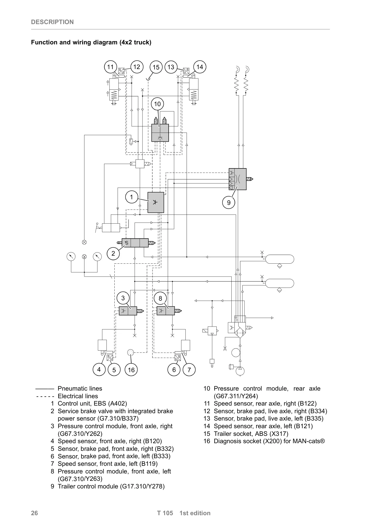
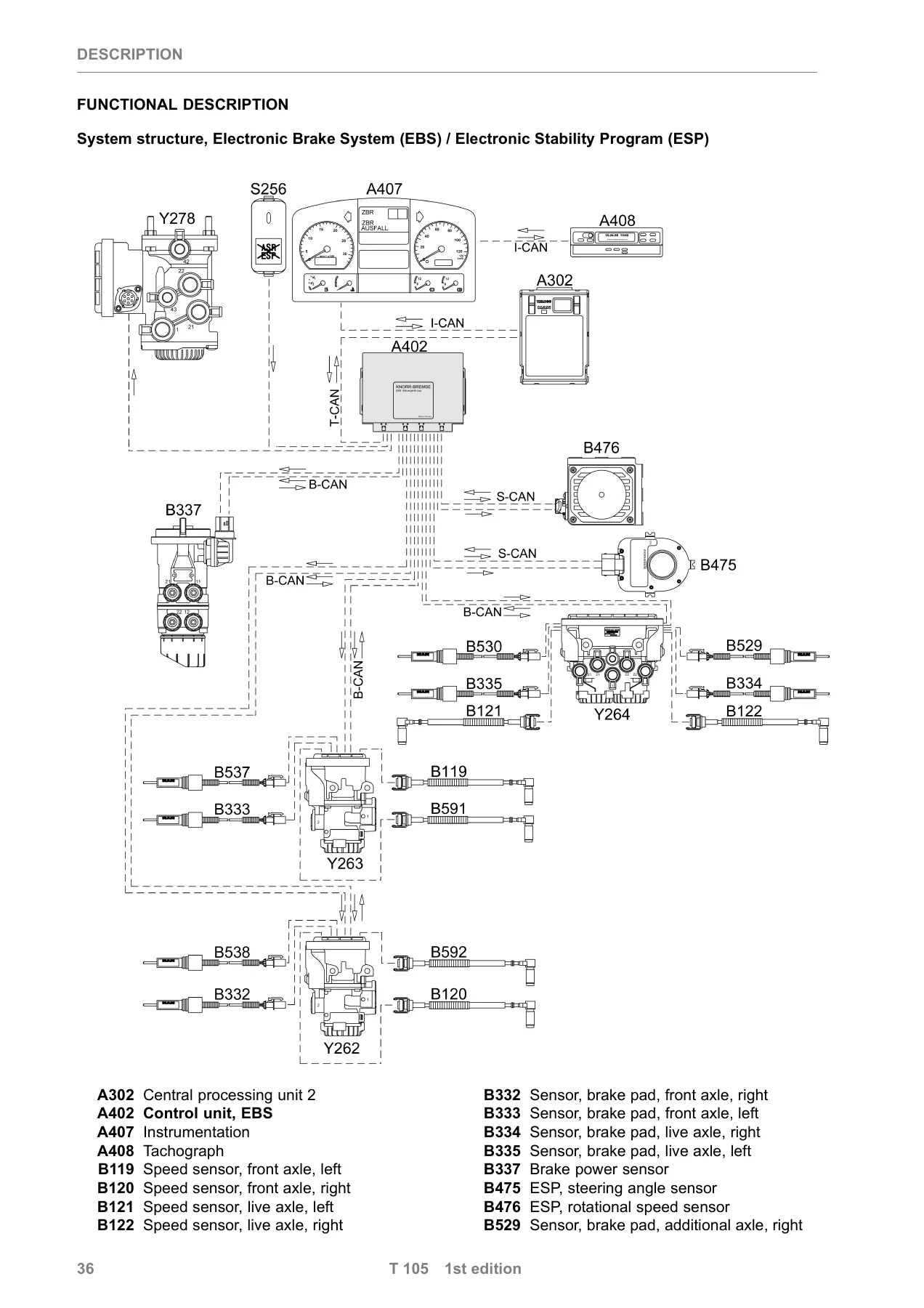
This section shows the complete EBS/ESP system structure with all the components identified, then works through the electro-pneumatic concept, single-circuit electronic control redundancy, the block diagram, the concept for pressure selection in the pressure control modules, and how the EBS communicates over the CAN databus. It includes the connector pin assignments for the EBS control unit X1, X2, X3 and X4, so you can identify each line and its function during diagnosis or repair. The interfaces to other vehicle systems are described along with the CAN databus system structure for TGA.
Component Descriptions
Each major component is described in its own section, with design illustrations, installation position photographs and technical explanations:
- Control unit, EBS (A402) — design, installation position on TGA and X models, voltage supply, computer, pressure control module supply, CAN interfaces and output stages
- Service brake valve with integrated brake power sensor (G7.310/B337) — design, installation position, brake power sensor signals and monitoring
- Pressure control module, 1-channel (G67.310/Y262 right and G67.310/Y263 left) — design, installation position, pin assignments and the three operating states
- Pressure control module, 2-channel (G67.311/Y264) — design, installation position and brake pressure diagram
- Trailer control module (G17.310/Y278) — design, installation position and the electrical/pneumatic functions of the trailer brake line control
- Brake pad sensors (B332, B333, B334, B335, B529, B530, B537, B538) — design, installation and brake pad wear control
- Speed sensors (B119, B120, B121, B122, B591, B592) — design, installation, monitoring and vehicle speed calculation
- Steering angle sensor (B475) — design, installation position, measuring principle and technical data
- Rotational speed and lateral acceleration sensor (B476) — design, installation position, measuring principle and calibration
Diagnosis, SPN Fault Codes and Test Step List
The diagnosis section explains the on-board diagnosis structure, the K-line and KWP-on-CAN systems, the diagnosis socket X200 in 12-pin and HD-OBD versions, and their installation positions on TGA and X models. The main diagnosis functions are described: fault detection, fault analysis, occurrence, meaning, identification, fault type, fault saving and simulation for troubleshooting. The manual explains the malfunction displays, the display/indicator priorities and how fault texts are structured, including global and specific fault text messages.
The SPN list (fault codes) and fault code description is the heart of the diagnostic material. It lists the fault codes that appear on the instrumentation display or the MAN-cats screen in the event of a fault, with the SPN, plain-text description, fault status (FMI), fault display, effect of fault, cause of fault and remedy for every entry. The FMI (Failure Mode Identification) status indicators are explained so you can interpret each fault type correctly. The test step list then enables the components and functions of the EBS/ESP to be checked with a multimeter, with resistance and voltage measurement tables covering the control unit ground supply, the ASR/ESP spin threshold button, the trailer socket, the CAN databus, the speed sensors, the brake pad sensors, the pressure control modules, the trailer control module and the ESP voltage supply. Expected values and measurement points are given for each test.
Additional Wiring Diagrams
The final section contains the additional wiring diagrams, starting with an overview and a 3-axle vehicle overview. The diagrams include:
- Wiring diagram No. 81.99192.1651 — EBS5 for 2-axle vehicle (TG), three sheets
- Wiring diagram No. 81.99192.1845 — EBS5 for 3-axle vehicle (TG), four sheets
- Wiring diagram No. 81.99192.1652 — ESP dynamic handling control
- Wiring diagram No. 81.99192.1895 — ASR/ESP spin threshold button
- Wiring diagram No. 81.99192.2862 — ASR/ESP check lamp
Each diagram is accompanied by a legend identifying the components, plug connections, fuses, check lamps and pressure control modules involved.
Why This MAN EBS5 ESP System Description Belongs in Your Workshop
When an EBS or ESP fault appears on a MAN TGA or X model truck, the difference between a quick, correct repair and a costly guessing game comes down to having the right technical information. This MAN EBS5 ESP System Description T105 gives you the system layout, the component functions, the electrical connector pin assignments, the SPN fault code list with causes and remedies, and the step-by-step measurement values needed to trace faults to their source. Instead of replacing parts on suspicion, you can follow the manufacturer’s diagnostic logic from the fault code through to the component test and the repair.
The manual covers the complete EBS5 and ESP system as fitted across the TGA and rough-terrain X model ranges, including the pressure control modules on the front and rear axles, the trailer control module, the brake power sensor integrated in the service brake valve, the wheel speed sensors and the ESP sensors. It explains not only what each component does but how the system behaves when something fails, which is essential when you need to understand a back-up level or a reduced-functionality state reported by the control unit.
The SPN fault code descriptions are written for practical use: each entry tells you the fault status, what the driver sees, what effect the fault has on vehicle functions, what typically causes it, and exactly what to check and repair. The test step list then converts that diagnostic direction into measurable values at the connector pins, so you can confirm a wiring fault, a sensor fault or a control unit fault before committing to a replacement.
IMAGES PREVIEW
This MAN EBS5 ESP system description is delivered as an instant PDF download. There is no shipping, no waiting for a disc or a printed book, and no restriction on where you use it — open it on a laptop in the workshop, on a tablet next to the vehicle, or print the pages you need for the job. Whether you are diagnosing an ABS warning lamp, tracing an ESP sensor fault, setting up a trailer control module or simply trying to understand how the electro-pneumatic brake system on a TGA is put together, this manual gives you the manufacturer’s own technical description in a searchable, printable PDF.
Reviews
There are no reviews yet.