
MAN Trucks EBS2 Knorr ESP Electronic Brake System & Stability Program System Description T61 2nd Edition 81.99593-4732 PDF
Original price was: $49.95.$29.95Current price is: $29.95.
MAN Nutzfahrzeuge EBS2 Knorr Electronic Brake System and Electronic Stability Program (ESP) System Description T61, 2nd Edition. Covers TGA and X-series trucks with detailed component descriptions, diagnostic SPN fault codes, wiring diagrams and test procedures.
Description
MAN EBS2 Knorr ESP – System Description T61, 2nd Edition
This system description manual covers the Electronic Brake System (EBS2 Knorr) and the Electronic Stability Program (ESP) as fitted to MAN TGA and X-series trucks. Published by MAN Nutzfahrzeuge Aktiengesellschaft under document number 81.99593-4732, the 2nd edition of System Description T61 carries a copy deadline of 02.2008 and spans 284 pages of technical content, component descriptions, diagnostic fault code tables and wiring diagrams. It is the reference document for understanding how the Knorr EBS2 system and its integrated ESP function operate on MAN commercial vehicles.
File Details
- Manual type: System Description / Technical Manual
- Brand: MAN Nutzfahrzeuge AG
- Equipment: MAN TGA and X-series trucks (rough-terrain models)
- Systems covered: EBS2 Knorr Electronic Brake System, Electronic Stability Program (ESP)
- Document number: 81.99593-4732
- Edition: 2nd Edition, T61
- Copy deadline: 02.2008
- Language: English
- Pages: 284
- Format: PDF
Chapters Covered
- Abbreviations
- Introduction (Safety instructions, Model overview, Explanatory notes to the wiring diagrams)
- Device Description (System description, EBS, ESP, Interfaces to other systems, CAN database structure)
- Functional Description (System structure, EBS, ESP)
- Description of Components (EBS control unit, service brake valve, pressure control modules, trailer control module, ALB sensor, brake sensors, speed sensors, ESP control unit, steering angle sensor, rotational speed and lateral acceleration sensor)
- Diagnosis (General information, SPN list and fault code description for EBS and ESP, test step list)
- Wiring Diagrams (Overview for 2-axle, 3-axle and 4-axle vehicles)
Introduction
The opening chapters set out the safety instructions that apply when working on the brake system, covering dust extraction requirements, visual and function checks after any brake work, handling of brake fluid as hazardous waste, and the use of MAN-cats test systems for ABS/ASR function checks. The model overview lists the TGA and X-series model designations to which the EBS2 and ESP systems apply. The explanatory notes to the wiring diagrams explain how to read the electrical schematics, including component designations, installation positions, plug connections, cable numbers, cable colours and cross-section information.
Device Description
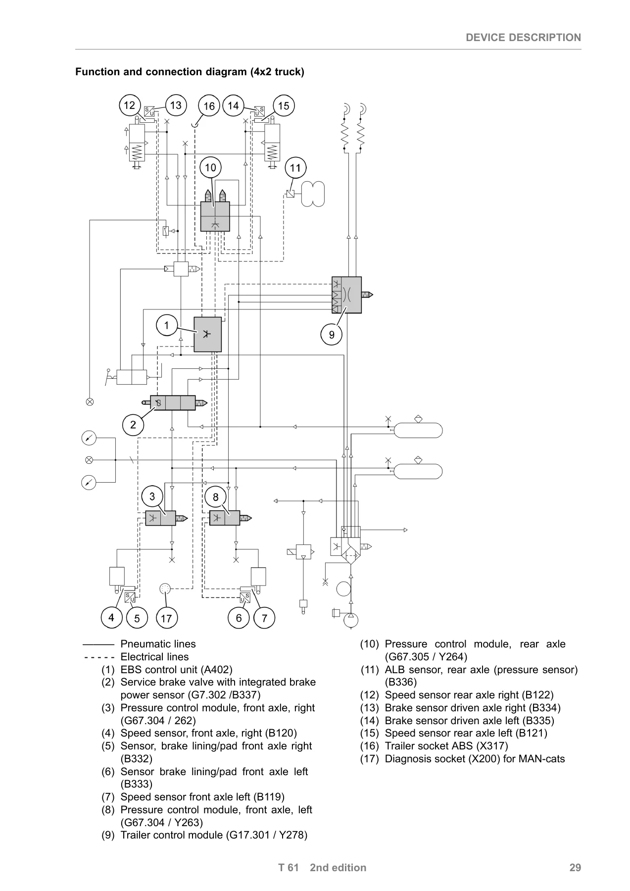
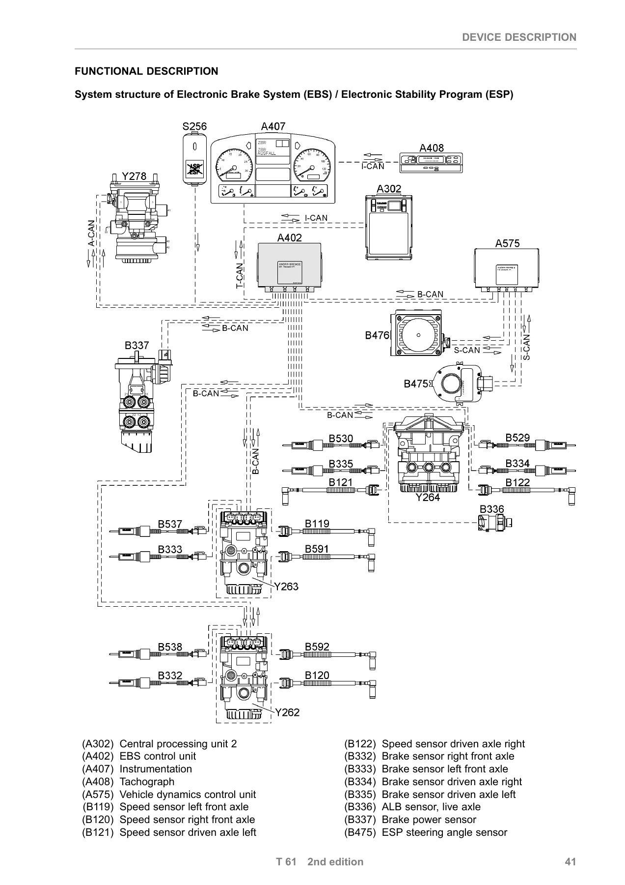
The device description begins with the system description, which introduces the EBS sub-functions: EPB (electro-pneumatic brake system), ABS (Anti-lock Brake System), ASR (Anti-Spin Regulator) and ESP (Electronic Stability Program). It details the two-circuit pneumatic control circuit, the single-circuit electro-pneumatic master control circuit, the dual-circuit pneumatic back-up circuit, the 24 V vehicle system voltage, the CAN databus architecture (Powertrain CAN, Trailer CAN, Brake CAN) and the EOL-programmable system configuration. The ESP section covers general information, vehicle types and variants, changes to the vehicle, limits of ESP functions and the reduced roll-over risk (RSP) feature. The interfaces to other systems chapter lists the control units that communicate via the various CAN databuses (T-CAN, A-CAN, H-CAN, M-CAN, I-CAN), and the CAN database system structure diagrams show the network topology for TGA and rough-terrain trucks. The functional description that follows provides the system structure of EBS/ESP, along with the operating principles of the EBS sub-functions (EPB, ABS, ASR, ESP), the ABS control procedures (IR, IRM, SL, SSM), the ASR engine and brake governors, automatic tyre compensation, coupling force control, and the function and connection diagram for the trailer.
Description of Components
This section describes each major component with design illustrations, installation locations for TGA and X models, pin assignments and electrical connector details. Components covered include the EBS control unit (A402), the service brake valve with integrated brake power sensor (G7.302/B337), the 1-channel pressure control modules for the front axle (Y262/Y263), the 2-channel pressure control module for the rear axle (Y264), the trailer control module (Y278), the ALB sensor on the rear axle (B336), the brake sensors (B332, B333, B334, B335, B529, B530, B537, B538), the speed sensors (B119, B120, B121, B122, B591, B592), the ESP control unit (A575), the steering angle sensor (B475) and the rotational speed and lateral acceleration sensor (B476). Each component entry provides technical data, operating voltage ranges, current consumption figures, measuring principles, calibration procedures and connector pin assignments.
Diagnosis
The diagnosis chapter is the largest section of the manual and provides the complete SPN (Suspect Parameter Number) fault code listings for both the EBS and ESP systems. It begins with general information on the on-board diagnosis system, the K-line and KWP-on-CAN structure, and the main diagnosis functions. The EBS fault code tables are organised by component group: control unit fault messages, analogue signal fault messages, engine interface fault messages, CAN databus fault messages, and individual fault messages for each pressure control module (front axle left and right, rear axle left and right, 2nd rear axle left and right) and the trailer control module. Each fault entry provides the SPN plain text, fault indication (which warning lamps are activated), effect of fault, cause of fault, remedy and the resulting emergency function (function level). The ESP SPN list covers control unit faults, EEPROM faults, configuration errors, lateral acceleration sensor faults, steering angle sensor faults, rotational speed sensor faults and CAN communication faults. The test step list provides a structured procedure for checking EBS and ESP components with a multimeter, including resistance measurements for ground lines, CAN databuses, speed sensors and brake sensors, and voltage measurements for the voltage supply, brake power sensor, brake sensors, ALB sensor, pressure control modules, trailer control module, diagnosis K-line and CAN databuses, with nominal values and expected measuring ranges.
Wiring Diagrams
The final section contains the wiring diagram overviews for EBS on 2-axle vehicles and for EBS on 3-axle and 4-axle vehicles. These diagrams show the central electrical system (A100), central computer 2 (A302), EBS control unit (A402), speed sensors, brake sensors, ALB sensor, brake power sensor, fuses (F161, F162), ASR spin threshold increase button (S256), diagnosis socket (X200), trailer socket (X317), pressure control modules (Y262, Y263, Y264) and trailer control module (Y278), along with the associated plug connections, cable numbers, colours and cross-sections.
What This Manual Enables You to Do
With this MAN EBS2 Knorr ESP system description, a technician or workshop can correctly diagnose and repair the electronic brake system and stability program on TGA and X-series trucks. The manual supports fault finding using the SPN fault code tables, component testing using the test step list and a multimeter, understanding of the system architecture and CAN databus communication, and correct handling of the pressure control modules, trailer control module and ESP sensors. It also provides the wiring information needed to trace electrical faults in the EBS/ESP harness and verify voltage supplies, ground connections and CAN databus resistances.
Why This Manual Matters
Correct diagnosis of EBS and ESP faults is critical on modern commercial vehicles. The brake system is a safety-critical system, and the ESP function directly affects vehicle stability and roll-over prevention. Using the correct fault code descriptions, emergency function levels and test procedures ensures that repairs are carried out to MAN specifications, that the right component is replaced, and that the system returns to full functionality. The wiring diagrams and connector pin assignments allow accurate electrical testing without guesswork, and the component descriptions provide the technical data needed to verify sensor operation and system pressures.
IMAGES PREVIEW
Instant PDF Delivery
This MAN EBS2 Knorr ESP System Description T61 is delivered as a PDF file immediately after payment. There is no shipping and no waiting for a physical book. The file can be viewed on any device — laptop, tablet or smartphone — and relevant pages can be printed for use in the workshop. Whether you are diagnosing an ESP warning light, replacing a pressure control module, calibrating a steering angle sensor or tracing a CAN databus fault, this manual gives you the reference information directly from MAN Nutzfahrzeuge.
Reviews
There are no reviews yet.