
MAN EDC MS 6.1 Electronic Diesel Control System Description T17-A3 2nd Edition – Trucks, Coaches & Buses Electrical Repair Manual PDF
Original price was: $59.95.$34.95Current price is: $34.95.
The complete MAN EDC MS 6.1 electrical system manual — System Description T 17-A3, 2nd edition, document 81.99598.5202. Covers the EDC control unit, lifting-element injection pump, all sensors and actuators, the full SPN fault code list, workshop test steps, troubleshooting charts and the complete wiring diagrams for MAN trucks, TG and TGA models, coaches, intercity and urban regular-service buses.
Description
MAN EDC MS 6.1 Electronic Diesel Control — System Description T17-A3, 2nd Edition
This is the complete electrical system and diagnostic manual for the MAN EDC MS 6.1 electronic diesel control system used across MAN commercial vehicles. Issued by MAN Nutzfahrzeuge Aktiengesellschaft under document number 81.99598.5202 as System Description T 17-A3, 2nd edition, with a copy deadline of 01.2004, it covers the engine-mounted EDC control unit, the lifting-element injection pump, every sensor and actuator in the injection chain, the complete SPN fault code library, the workshop test step list, the troubleshooting chart and program, and the full wiring diagrams for trucks, coaches, intercity buses and urban regular-service buses.
Where the T17-A1 manual described the earlier MS 5 system, this edition documents the MS 6.1 arrangement in which an engine-mounted EDC control unit handles the basic functions and receives requested torque over the CAN databus from the vehicle management computer. Every value in this manual — pin numbers, cable colours, line numbers, resistance ranges, voltage windows, oscilloscope traces and connector shell colours — is printed exactly as MAN released it.
File Details
- Manual type: Electrical system / Electronic Diesel Control system description, diagnosis and wiring diagram manual
- Brand: MAN Nutzfahrzeuge Aktiengesellschaft, Munich Plant
- System covered: Electronic Diesel Control EDC MS 6.1
- Document number: 81.99598.5202
- Edition: 2nd edition, T 17-A3
- Copy deadline: 01.2004
- Language: English
- File format: PDF
- Page count: 210 pages
Chapters Covered
- Introduction — Notes on safety; Guide to using the wiring diagrams
- Equipment description — System description, functional description, component description
- Diagnosis — SPN list EDC 6.1 stage 4 version V55; Test step list; Troubleshooting chart; Troubleshooting program
- Wiring diagrams — Overview EDC 6.1 trucks and the individual diagram sets for trucks, coaches, intercity buses and urban regular-service buses
- Connector pin assignment, multiplex
Notes on Safety and Using the Wiring Diagrams
The opening chapter sets out the working rules that apply to any repair on an EDC-equipped MAN vehicle: how to secure units during removal, how to work on the brake system and high-pressure lines, what is required before starting and running an engine, and the correct procedure for disconnecting and reconnecting batteries. It covers the dangers of battery gases and battery acid, the mandatory disconnection of the earth cable first, the requirement for a measurement device with an input resistance of at least 10 MΩ, and the warning about welding near polyamide tubes.
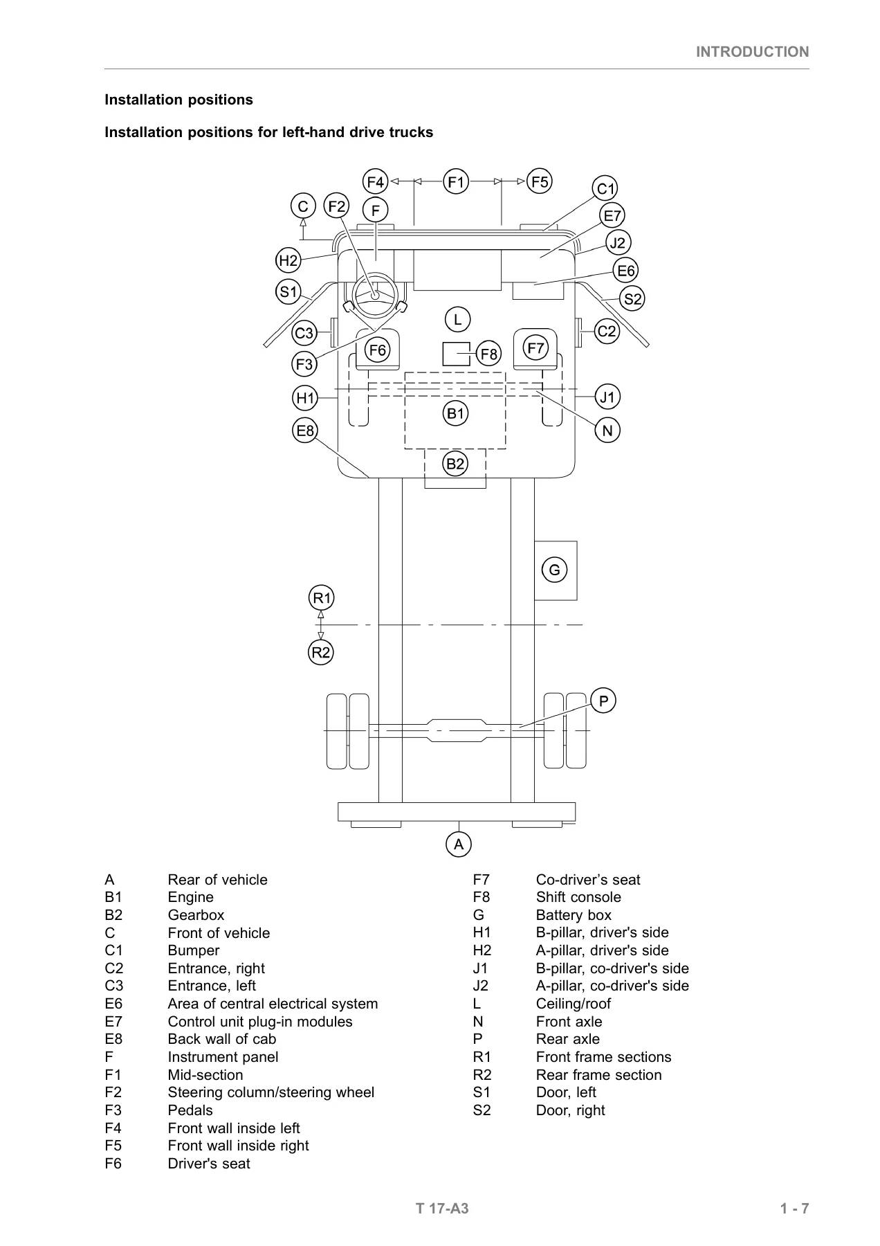
A separate section explains how to read the MAN wiring diagrams correctly, using a worked example that identifies the component designation, the installation position stamped on the central electrical system, the plug connection on its rear face, the cable number printed along the cable, conductor pathways on a printed circuit board, the sheet number and current path number that tell you where a line continues, and the installation-position letter code. This is the key that makes the rest of the wiring diagram chapter usable.
Equipment Description — System, Function and Components
The equipment description opens with the structure and operation of the MS 6.1 system, explains how requested torque is converted into a rack position, and lists the inputs the control unit processes. A system overview identifies the injection pump, both engine speed sensors, the needle movement sensor, boost pressure sensor, fuel temperature sensor, coolant temperature sensor, fuel pressure sensor, charge air temperature sensor and oil pressure sensor, together with the control unit, vehicle management computer, central on-board computer, instrumentation, check lamps, accelerator pedal and the CAN databuses (I-CAN, M-CAN, T-CAN and M-TCO-CAN).
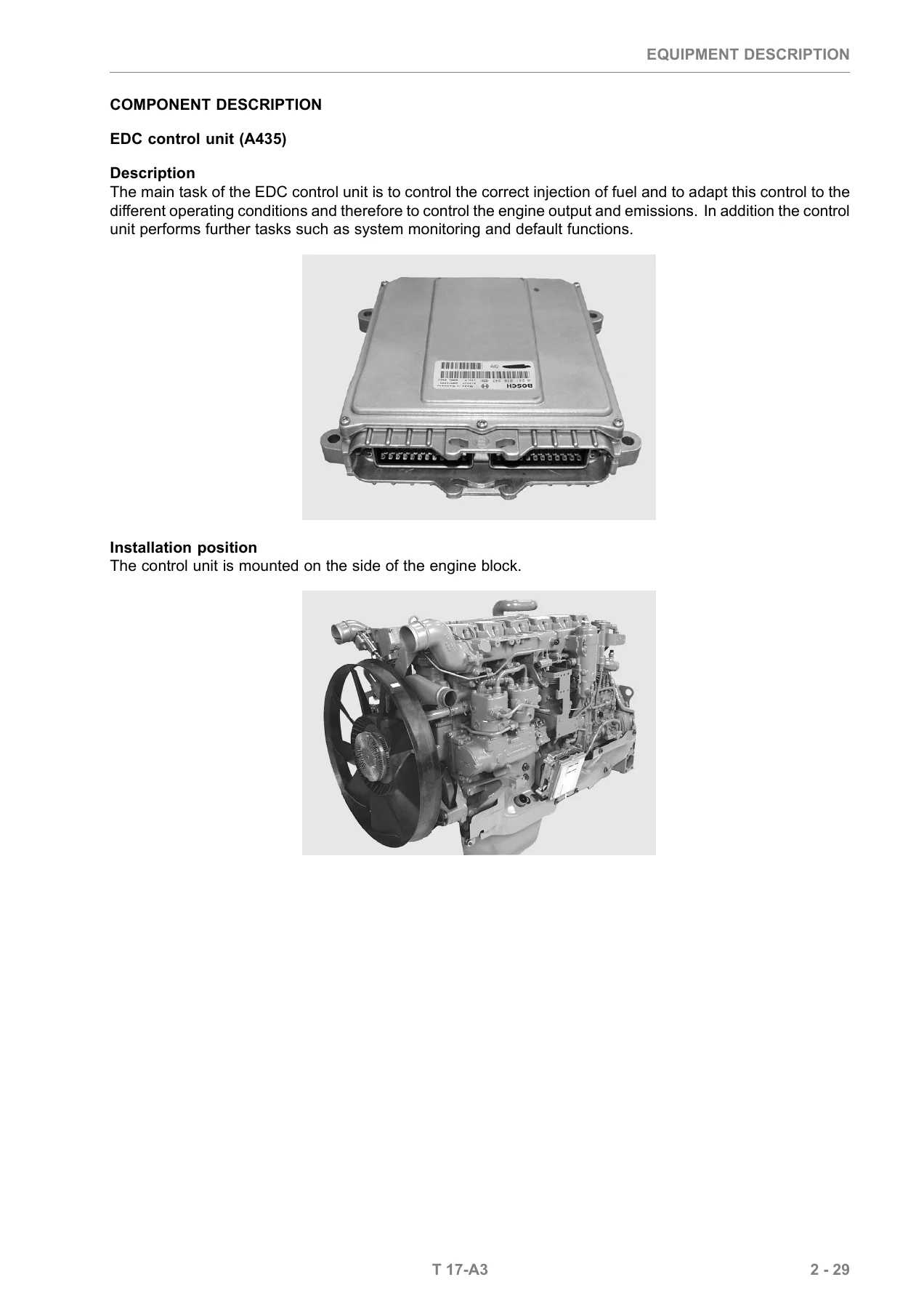
The control unit chapter gives the full 35-pole connector A and connector B pin assignment tables, including pin number, designation, line number and cable colour, and function for every pin — from primary and auxiliary engine speed sensor inputs and sensor grounds through to the CAN-H and CAN-L pins, the ISO K-line and the battery positive and negative feeds.
Each component then gets its own description with the control unit pin references, connector pin assignment table, sensor curve, measured-value table and installation position. The lifting-element injection pump Y130 is covered in detail, including how the element cylinder window, lifting element and rotating adjuster shaft change plunger lift to port closing, how the fuel quantity actuator linear solenoid drives the rack, and how the injection start positioner adjusts delivery timing. Resistance values are printed for the fuel rack position sensor reference coil, measuring coil and total, and for the fuel quantity actuator windings.
Engine speed sensor coverage distinguishes the primary sensor, which triggers a speed pulse 10° after TDC, from the auxiliary sensor at 18° after TDC, and warns clearly that if the two are installed the wrong way round the injection start will be 8° too late, producing heavy white smoke from a cold engine and, under certain conditions, destroying the injection pump camshaft. The needle movement sensor, boost pressure sensor, oil and fuel pressure sensors, fuel temperature sensor, coolant temperature sensor, charge air temperature sensor, main relay K170 and exhaust gas recirculation controller Y280 are all documented to the same level, with NTC resistance and voltage tables at 0 °C, 20 °C, 40 °C, 60 °C and 80 °C where applicable.
Diagnosis, Fault Codes and Troubleshooting
This is the chapter that makes the manual genuinely useful in the workshop. It explains how the EDC system performs continuous self-tests, how a signal range check polls every input for presence and plausibility, and exactly what happens when a fault is stored: identification of the fault code (SPN), identification of the fault type (FMI), assignment of the fault priority, recording of the fault frequency, and recording of two ambient conditions at the moment the fault was categorised. The self-healing counter behaviour for sporadic faults is explained, as is the priority table that tells you whether a red flashing central warning light with a STOP symbol, a steady red light, a steady yellow light or no display at all applies.
The SPN list runs through the complete fault library, including engine speed acquisition faults on the primary and auxiliary sensors, polarity reversal and sensor mix-up, fuel rack position acquisition, fuel quantity actuator steady-state deviation, coolant, charge air and fuel temperature sensors, boost pressure and oil pressure plausibility, exhaust gas recirculation steady-state deviation, main relay blocked, CAN Busoff and timeout states, the serial EEPROM checksum faults, monitoring module faults, redundant engine speed monitoring, immobiliser pairing and the CRT communication faults — each with its fault indication, effect of fault, cause of fault and system reaction.
The test step list provides a structured sequence for the engine stopped and running, with pin-to-pin measurement points and desired values: fuel rack position sensor resistance 18–25 Ω, engine speed sensors 0.8–1.1 kΩ, lifting-element positioner 1.2–2.0 kΩ, needle movement sensor 90–130 Ω, fuel quantity actuator 0.7–1.3 Ω, CAN connection 115–120 Ω, EGR activation 80–110 Ω and the IMR relay 15–30 Ω. There is also a procedure for checking the capacitance reserve of the fuel rack position sensor oscillating circuit and a reminder to delete the fault memory with MAN-cats after completing the tests.
The troubleshooting chart maps symptoms against possible causes and SPN numbers, from a starter that does not engage or turns without the engine starting, through sudden or temporary engine stops, engines that only start with the accelerator fully pressed, engines that will not accelerate past idling, and irregular running, spontaneous interruptions of tractive power, unstable idle, unusual combustion noises and smoke output. The troubleshooting program then gives general guidance on line testing order, on reading out and documenting the entire fault memory before disturbing the system, and on the test box and adapter wiring harness used at the control unit connector.
Wiring Diagrams for Trucks, Coaches and Buses
The wiring diagram chapter opens with an EDC 6.1 truck overview legend and then presents complete diagram sets for the specific vehicle families, each headed by its own MAN wiring diagram number: 81.99192.2795 for trucks, X models with EGR (EURO 3); 81.99192.2986 for TG trucks with EGR (EURO 3) and TG trucks without EGR (EURO 2); 81.99289.5892 for coaches; 81.99289.5961 for intercity buses with engine D2866 LUH 27/28/29; and 88.99289.6910 for urban regular-service buses. Sheets show the positioner, fuel temperature sensor, boost pressure sensor, charge air temperature sensor, EGR cylinder, water temperature sensor, engine speed sensors, needle movement sensor, oil pressure sensor, fuel pressure sensor, earthing points, the CAN databus wiring, the control unit connector pin-outs and the supply and relay circuits.
Line numbers, cable colours, connector designations such as X1906, X1907, X1982, X1983, X1990, X3344, X1559, X337 and X1001, ultrasonic welds, threaded pins on the motor power box and plug connections are all printed as released, so the diagram you are holding matches the harness in the vehicle rather than a simplified redraw.
Connector Pin Assignments — Multiplex Nodes
The final chapter documents the multiplex node connector pin assignments for front control unit 1.3 (A413), rear right 1.8 (A418), front right 2.1 (A421) and rear left 2.8 (A428), with component, pin, identifier, line, function, input/output direction, high/low side, amperage rating and the wiring diagram sheet and sheet number where each signal appears.
What This MAN EDC MS 6.1 Manual Lets You Do
With this manual in front of you, the EDC MS 6.1 injection system stops being a black box. You can pull a fault code, look up its SPN and FMI, read the priority to know whether the vehicle can continue or must stop immediately, and follow the test step list straight to the suspect circuit — measuring engine speed sensor resistance between pin A01 and A13, checking the fuel rack position sensor between A33, A34 and A35, verifying the CAN databus at around 120 Ω between B11 and B12, or confirming the main relay switches to battery voltage with a 0.5 to 5 second delay after the ignition is switched off.
You can diagnose a crank-no-start by working through the troubleshooting chart, trace the exact cause of a steady red warning lamp or an engine that will only idle, correct a mix-up between the primary and auxiliary engine speed sensors before it damages the injection pump camshaft, resolve EGR steady-state deviation, and identify immobiliser pairing faults between the EDC control unit and the vehicle management computer.
And when you need to trace a wire, you have the manufacturer’s own wiring diagrams for X models, TG trucks with and without EGR, coaches, intercity buses and urban buses, complete with line numbers and connector references, plus the multiplex node pin assignments for the vehicle body systems.
Every procedure in this manual depends on having the correct specification in front of you — the resistance window, the voltage range, the pin number, the cable colour. Guessing at an EDC system is how injection pumps, sensors and control units get destroyed. Working from the printed values is how the job gets done once and correctly.
IMAGES PREVIEW
The manual is delivered as an instant PDF download. There is no shipping, no waiting for a parcel and no postage cost. Once payment clears you can open it immediately on a laptop, tablet or phone in the workshop, print the sheets you need for the job, and keep the wiring diagrams beside you at the vehicle. Everything in this description is included in the single file you download.

Reviews
There are no reviews yet.