

MAN D2066 LOH01-LOH12 Common Rail Engine Repair Manual A41 Stage 2 – 4th Edition Workshop Manual PDF
Original price was: $44.95.$29.95Current price is: $29.95.
Complete MAN D2066 common rail in-line engine repair manual covering LOH01 through LOH08 and LOH10 through LOH12. A41 Stage 2, 4th edition workshop manual with full procedures, torque values, illustrations and technical data for Euro 3 and Euro 4 engines.
Description
MAN D2066 Common Rail In-Line Engine Repair Manual – A41 Stage 2, 4th Edition
This is the complete MAN D2066 repair manual for the common rail in-line engine family, covering D2066 LOH01 through LOH08 and D2066 LOH10 through LOH12. Published as the A41 Stage 2, 4th edition under document number 81.99185-5342, this workshop manual is the authoritative reference for every major repair, overhaul and diagnostic procedure on these 6-cylinder diesel engines. Whether you are servicing a Euro 3 or Euro 4 variant, this manual provides the exact procedures, specifications and tightening sequences required to carry out the job correctly.
File Details
- Manual type: Repair Manual / Workshop Manual
- Brand: MAN Truck & Bus AG
- Engine family: D2066 common rail in-line engine
- Covered variants: D2066 LOH01-LOH08, D2066 LOH10-LOH12
- Document number: 81.99185-5342
- Edition: A41 Stage 2, 4th edition
- Date: 07.2015
- Language: English
- Format: PDF
- Page count: 534 pages
Chapters Covered
- Introduction
- Engine electronics
- Cooling system
- Mounted components
- Common Rail System
- Turbocharging
- Intake/exhaust system
- Cylinder head
- Valve control
- Timing gears
- Engine lubrication
- Crankshaft seals
- Crankshaft drive
- Engine case
- Engine brake system
- Technical Data
Introduction
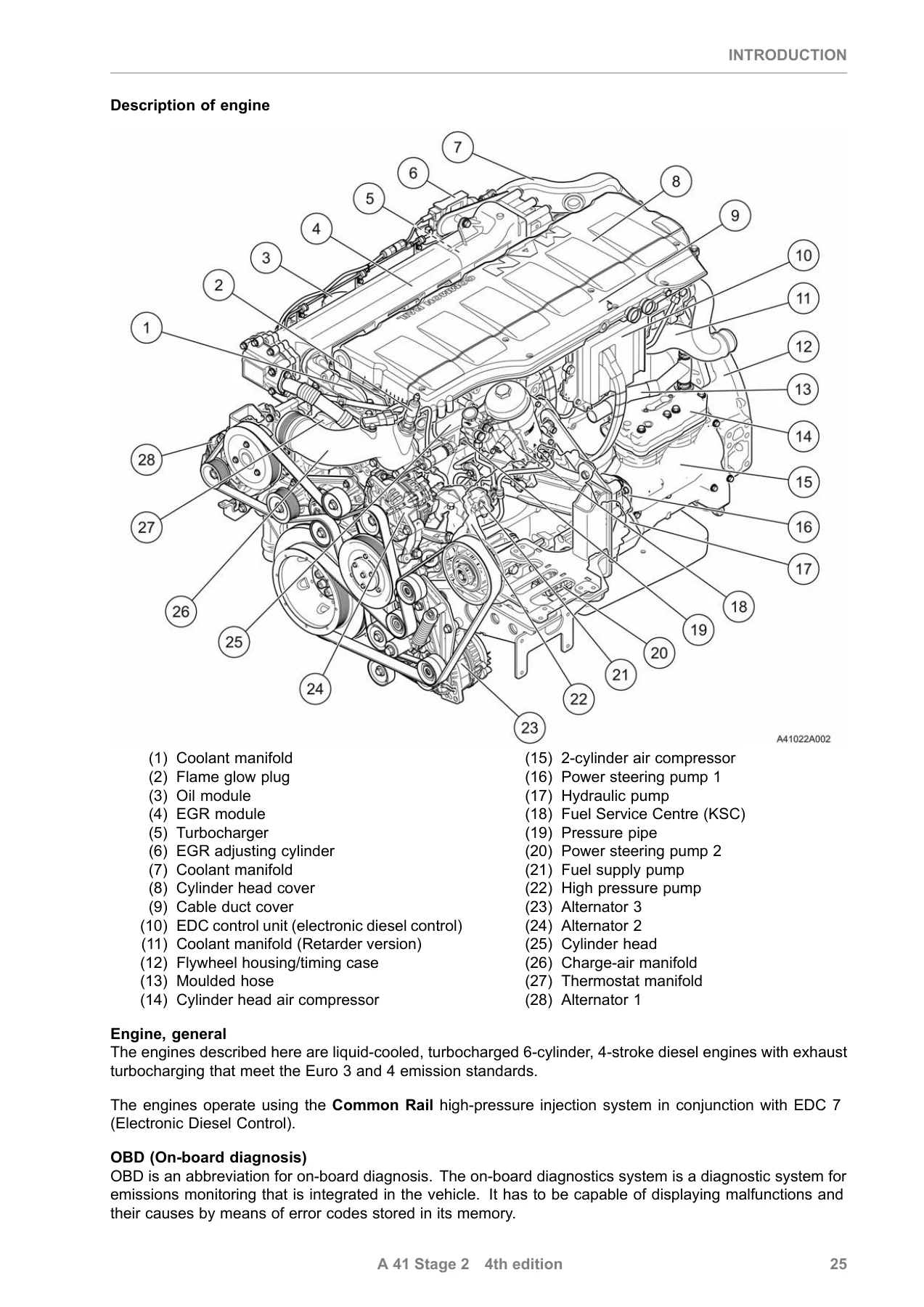
Covers safety instructions, model plate and model designation explanation, characteristic data for every LOH variant, and a full description of the engine. The characteristic data tables list rated output, bore, stroke, displacement, firing order, nominal rpm, low idling speed and maximum torque for each D2066 variant. The engine description breaks down the crankcase, crankshaft, connecting rods, pistons, cylinder head, camshaft, lubrication, cooling, intake/exhaust, fuel system, high-pressure system, injectors, flame start system, engine brake and starter.
Engine Electronics and Common Rail System
Detailed removal and installation procedures for the engine electrical system, including temperature sensors, oil level sensors, pressure sensors, pressure switches, rail pressure sensors, crankshaft sensors, speed sensors, charge pressure sensors and flame glow plugs. The Common Rail System chapter covers protective sleeves for injectors and pressure pipes, injector and pressure pipe removal/installation, high-pressure pump and high-pressure pump drive (both fuel-lubricated and oil-lubricated variants), fuel service centre (KSC) removal, installation and dismantling, flame-start system servicing, and engine control unit removal and installation. Specific torque values are given throughout, including high-pressure line tightening stages and injector pressure flange torque sequences.
Cooling System and Mounted Components
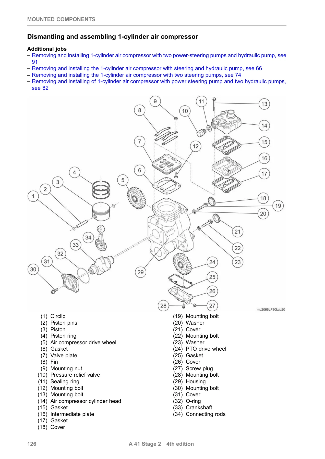
The cooling system chapter provides complete procedures for the coolant manifold (both with and without retarder), thermostats, thermostat housing, coolant pump and distributor housing. The mounted components chapter covers the air compressor in 1-cylinder and 2-cylinder configurations with various steering and hydraulic pump combinations, including full dismantling and assembly instructions with piston, connecting rod, crankshaft and valve plate details. Starter removal and installation, belt drive servicing, alternator 1, 2 and 3 removal and installation, and refrigerant compressor removal are all documented with torque specifications and special tool references.
Turbocharging and Intake/Exhaust
Charge-air pipe removal and installation, turbocharger removal and installation with oil pressure line and oil return line procedures, and compressor housing servicing. The intake/exhaust chapter covers the EGR module with and without intermediate plate, including dismantling, assembly, check valve servicing and EGR adjusting cylinder pre-load adjustment. Exhaust manifold removal, installation, dismantling and assembly are covered, including heat shield and multi-piece ring details.
Cylinder Head and Valve Control
Cylinder head removal and installation with the full 26-bolt tightening sequence and multi-stage torque values. Valve clearance checking and adjustment, including intake, exhaust and EVB settings, with the engine in the correct setting position. Valve-stem seal removal and installation. The valve control chapter covers camshaft and camshaft bearing removal and fitting, camshaft gear and intermediate gear servicing, axial and radial play measurement, and valve timing checking.
Timing Gears
Front drive gears and rear timing gears (both crankshaft seal flywheel version and crankshaft seal crankshaft gear version) are covered in full. This includes the high-pressure pump drive intermediate gear, crankshaft gear, large intermediate gear, small intermediate gear and air compressor intermediate gear, with backlash, axial play, radial play, height and inside/outside diameter measurements and tolerances for each component.
Engine Lubrication and Crankshaft Seals
Oil module removal, installation and dismantling, including oil cooler, pressure relief valve, oil separator, oil filter and connecting manifold. Oil sump and oil intake pipe removal and installation, oil injector nozzle servicing, and oil pump removal and installation with ring gear and oil pump pinion measurements. Crankshaft seal chapters cover front and rear seal removal and installation for both the flywheel version and the crankshaft gear version, including race replacement and repair level determination.
Crankshaft Drive
Vibration damper removal and installation. Flywheel servicing for manually operated gearboxes (flywheel crankshaft seal version), automatic gearbox flywheel (crankshaft seal flywheel version), gearbox flywheel (crankshaft seal crankshaft gear version), automatic gearbox flywheel with race (crankshaft seal crankshaft gear version) and dual-mass flywheel (crankshaft seal crankshaft gear version). Piston and connecting rod removal, installation, checking and assembly, including piston ring installation, piston pin fitting, connecting rod bearing shell alignment and piston protrusion measurement. Crankshaft removal and installation with bearing cover tightening sequence and axial/radial play measurement.
Engine Case and Engine Brake System
Flywheel housing/timing case removal and installation, cover removal and installation, and cylinder liner removal and installation with cylinder liner stand out measurement. The engine brake system chapter covers engine brake removal and installation, including proportional valve, positioning cylinder and adjusting cylinder pre-load adjustment.
Technical Data
A comprehensive technical data section consolidates all the key specifications, torque values, wear limits, clearances and adjustment values from across the manual, making it a quick reference for the workshop.
Why This MAN D2066 Repair Manual Is Essential
These engines are built for heavy-duty commercial operation, and getting the repair procedures right is not optional. This MAN D2066 workshop manual gives you the exact torque sequences for cylinder head bolts, connecting rod bolts, crankshaft bearing covers and flywheel mounting bolts. It provides the wear limits for camshaft bearings, connecting rod bearings, piston rings, cylinder liners and timing gears. It shows you how to set valve clearances, EGR adjusting cylinder pre-load, engine brake pre-load and injector pressure flange torque. Without these specifications, you risk engine damage, premature wear or a repair that fails prematurely.
The manual covers both Euro 3 (LOH10, LOH11, LOH12) and Euro 4 (LOH01 through LOH08) variants, so it is suitable for a wide range of MAN truck and bus applications. The procedures are written for trained technicians but are detailed enough to guide anyone with mechanical experience through complex operations such as cylinder head removal, timing gear replacement, high-pressure pump servicing and crankshaft installation. Each chapter includes special tool references, service product specifications and warnings where particular care is required.
IMAGES PREVIEW
This MAN D2066 repair manual is delivered as an instant PDF download. There is no shipping, no waiting and no physical book to keep track of. You can access it on any device, search it digitally and print only the pages you need for the job at hand. Whether you are running a workshop, maintaining a fleet or carrying out a major engine overhaul, this manual gives you the manufacturer-level information you need to do the job correctly the first time.
Reviews
There are no reviews yet.