
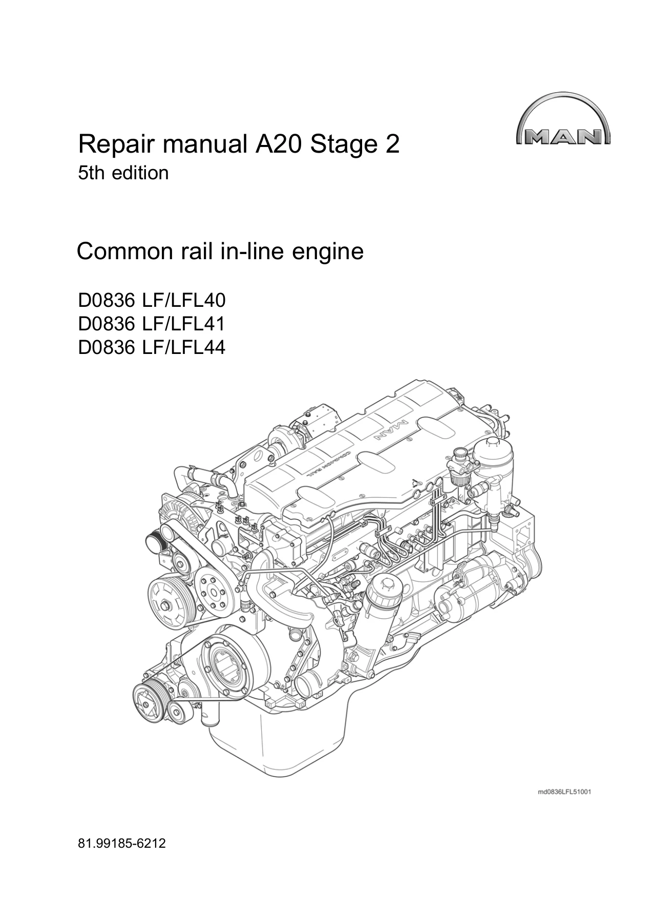
MAN D0836 LF LFL40 LFL41 LFL44 Common Rail Engine Repair Manual – A20 Stage 2 Workshop PDF
Original price was: $55.95.$34.95Current price is: $34.95.
Complete 5th edition MAN repair manual for D0836 LF/LFL40, LFL41 and LFL44 common rail in-line diesel engines. Covers full engine overhaul, Common Rail system, cooling, turbocharging, cylinder head, crankshaft drive and more. 394-page PDF workshop manual.
Description
MAN D0836 LF/LFL40, LFL41, LFL44 Common Rail Repair Manual – A20 Stage 2, 5th Edition
This is the complete 5th edition repair manual for the MAN D0836 LF/LFL40, D0836 LF/LFL41 and D0836 LF/LFL44 common rail in-line diesel engines, published under MAN document number 81.99185-6212. It documents the full range of workshop procedures for the A20 Stage 2 engine family: 6-cylinder, 4-valve, turbocharged and intercooled diesel engines running the Common Rail high-pressure injection system with EDC 7 electronic diesel control. Every major system is broken down into removal, installation, dismantling, assembly and checking procedures with the torque values, clearances and special tools called out where they belong.
File Details
- Manual Type: Repair Manual / Workshop Manual
- Brand: MAN Truck & Bus AG
- Engine Models: D0836 LF/LFL40, D0836 LF/LFL41, D0836 LF/LFL44
- Document Number: 81.99185-6212
- Edition: 5th edition
- Language: English
- Page Count: 394 pages
- File Format: PDF
Chapters Covered
- Introduction
- Engine electronics
- Cooling system
- Add-on units
- Common Rail system
- Turbocharging
- Intake/exhaust system
- Cylinder head
- Camshaft/camshaft bearing
- Timing gears
- Engine lubrication
- Crankshaft drive
- Crankshaft seals
- Engine housing
- Power take-off
- Technical Data
Introduction, Safety and Engine Identification
The opening chapter sets out the safety instructions that apply across the whole manual, then explains the model plate and model designation so you can identify exactly which D0836 variant you are working on. It includes the characteristic data tables for all three engines: the LFL40 rated at 176 kW / 240 hp with 925 Nm at 1200–1800 rpm, the LFL41 at 206 kW / 280 hp with 1100 Nm at 1200–1750 rpm, and the LFL44 at 240 kW / 326 hp with 1250 Nm at 1200–1800 rpm. All three share the same 108 mm bore, 125 mm stroke, 6871 cc displacement, 1-5-3-6-2-4 firing order, 2400 rpm nominal speed and 570 rpm idle speed. The description of engine chapter walks through the crankcase, crankshaft, connecting rods, pistons, cylinder head, camshaft, lubrication, cooling, intake/exhaust, fuel system and the front and rear PTO arrangements.
Engine Electronics and Cable Harness
This chapter covers the engine cable harness and the engine electronics themselves. It includes removal and installation of the complete cable harness with the routing, cable tie positions and connector locations shown, plus the EDC control unit removal and installation. You will find the sensor and actuator layout across the engine – speed sensors, oil level sensor, flame glow plug, temperature sensors, EGR adjusting cylinder, heating element, pressure sensors, rail pressure sensor, proportional valve and charging pressure sensor – with their tightening torques and electrical connection details.
Cooling System
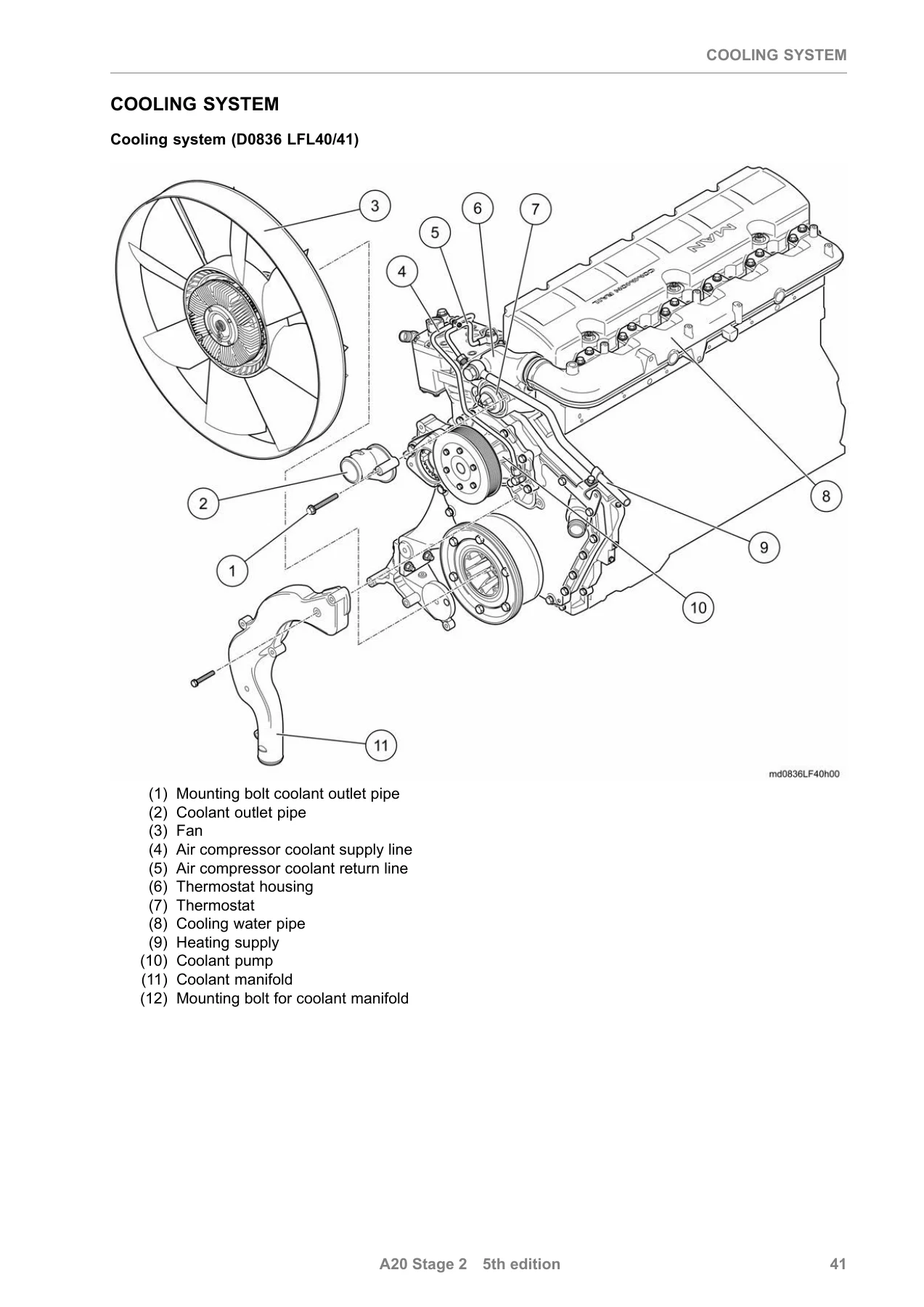
The cooling system chapter covers the fan in all three mounting variants (attachment to coolant pump, variant without hydraulic pump, variant with hydraulic pump), the coolant manifold, the thermostat with thermostat housing, and the coolant pump. The coolant pump section includes both dismantling and assembly procedures for the open impeller and closed impeller variants, with the impeller-to-housing dimension of 33.10–33.30 mm for the open impeller type and 0.5 mm gap for the closed impeller type. Thermostat opening temperature is specified at 83 °C.
Add-On Units
This large chapter covers everything driven off the engine: the front power take-off with its left-handed mounting bolt, the 1-cylinder air compressor including dismantling and assembly, the belt drive in four variants (without Frigoblock alternator, with Frigoblock alternator, with hydraulic pump, with stretchy belt), the alternator, the Frigoblock alternator, the starter motor, the refrigerant compressor and the hydraulic pump. Belt tensioning values, mounting torques and the procedures for each drive variant are all included.
Common Rail System
The Common Rail system chapter is the technical core of this manual. It covers the injectors and pressure pipe with protective sleeve part numbers, removal and installation of the injectors and pressure pipe with the exact tightening sequence for the mounting bolt (2 Nm first stage, 30 Nm final), pressure screw (10 Nm first stage, 55 Nm final) and high-pressure lines (10 Nm first stage, 60° final). The high pressure pump section includes its own protective sleeves, removal and installation, dismantling and assembly, and the 60 ml fuel fill level. The fuel service centre chapter covers the protective sleeves, removal and installation, and dismantling and assembly of the FSC with its filters, hand pump and pressure sensor. The flame-start system is covered for both the standard D0836 and the D0836 LFL44-specific arrangement. The EDC control unit chapter closes the section with its removal, installation and tightening sequence.
Turbocharging and Intake/Exhaust System
The turbocharging chapter covers the charge-air pipes and the turbo charger removal and installation, including the oil pressure line, oil return line and the critical step of filling the turbo charger with clean engine oil before first start. The intake/exhaust system chapter covers the air distributor pipe, the EGR module with its adjusting cylinder pre-load setting of 1.25 ± 0.25 mm, and the three-section exhaust manifold with its staged tightening sequence (25 Nm, then 45°, then final 45°).
Cylinder Head
The cylinder head chapter covers the rocker arm mechanism removal, installation, assembly and disassembly, the cylinder head itself with the 24-bolt tightening sequence (80 Nm, 150 Nm, 90°, 90°, final 90°), valve clearance checking and adjustment (inlet and exhaust both 0.50 mm, EVB brace setting 0.35 mm), and valve-stem seal removal and installation with the special tools required.
Camshaft, Timing Gears and Engine Lubrication
The camshaft chapter covers removal and installation of the camshaft and the camshaft bearings, with axial play of 0.140–0.270 mm and radial play of 0.060–0.120 mm. The timing gears chapter covers the intermediate gears, camshaft gear, crankshaft gear and oil pump drive gear with all tooth flank clearance values. The engine lubrication chapter covers the oil module with its oil cooler and filter, the oil sump and oil intake pipe, the oil pump with its 0.040–0.106 mm axial play, and the oil nozzles with their alignment procedure.
Crankshaft Drive and Crankshaft Seals
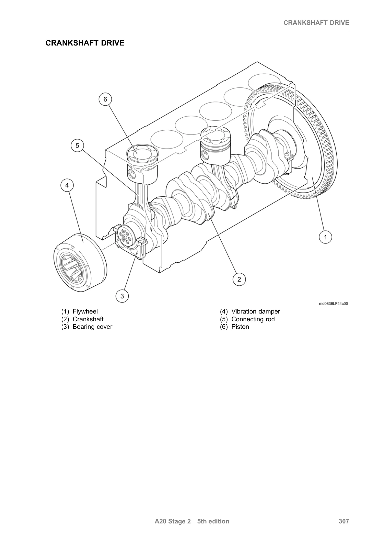
The crankshaft drive chapter covers the vibration damper (150 Nm + 90°), the flywheel for the manually operated gearbox (100 Nm + 90°) including starter ring gear replacement at 220–240 °C, the piston and connecting rod with full dimensional checking, and the crankshaft with its bearing clearances and axial play of 0.150–0.282 mm. The crankshaft seals chapter covers both the front and rear crankshaft seal removal and installation using the guide plate and spindle tooling.
Engine Housing and Power Take-Off
The engine housing chapter covers the crankcase ventilation, the flywheel housing in versions with and without PTO, the crankcase yoke with its tightening sequence, the timing case cover and timing case, and the cylinder liner with its protrusion specification of 0.01–0.06 mm. The rear power take-off chapter covers removal and installation of the PTO with its O-ring.
Technical Data
The Technical Data chapter consolidates all the torque values, clearances, tolerances and specification figures from across the manual into a single reference. This is where you find the injector mounting torques, high-pressure line torques, cylinder head bolt stages, main bearing and connecting rod bearing dimensions, piston and ring specifications, camshaft and crankshaft clearances, and the many other measured values you need when rebuilding or repairing these engines.
What This MAN D0836 Repair Manual Enables You to Do
With this manual in hand you can carry out a full engine overhaul on any D0836 LF/LFL40, LFL41 or LFL44 power unit: strip the engine down to the crankcase, check and replace pistons, connecting rods, crankshaft bearings, camshaft bearings, cylinder liners and valves; service the complete Common Rail fuel system including injectors, high pressure pump, pressure pipe and fuel service centre; rebuild the cooling system with the correct thermostat and coolant pump; replace the turbocharger and exhaust manifold; set valve clearances and EGR pre-load; and diagnose the EDC 7 engine electronics. The manual gives you the sequence, the torque, the clearance and the special tool number for each operation, so you are not working from memory or guesswork.
Why the Correct Procedures and Specs Matter
These engines operate with injection pressures of 1800 bar and above, and the internal tolerances on bearings, pistons and camshafts are measured in thousandths of a millimetre. A connecting rod bolt tightened to the wrong stage, a high-pressure line union not replaced after removal, a cylinder liner protrusion outside 0.01–0.06 mm, or an EGR adjusting cylinder pre-load that is out of tolerance can all lead to repeat failures, poor performance or engine damage. This manual provides the exact staged tightening values, the replacement rules for single-use components, and the measured limits that separate a correct repair from a comeback.
IMAGES PREVIEW
Instant PDF Delivery
This MAN D0836 LF/LFL40, LFL41 and LFL44 repair manual is delivered as a PDF download immediately after purchase. There is no shipping, no waiting for a physical book, and no restrictions on where you use it. Open it on a laptop or tablet in the workshop, print the pages you need for the job at hand, and keep the complete 394-page reference on file for every D0836 engine you work on.

Reviews
There are no reviews yet.