★ TRUSTED BY 321,897+ PROFESSIONALS WORLDWIDE
🏒
Trusted Business
Verified & Licensed
πŸ›‘οΈ
Virus Free Files
100% Safe Downloads
πŸ”’
Secure Payment
SSL Protected
⚑
Instant Delivery
Available Immediately
Sale!

Manitowoc 12000 & 12000E Crane Service Manual (Tier 3 Engine) – PDF Download

Original price was: $44.95.Current price is: $26.95.

Complete Manitowoc 12000/12000E (Tier 3 Engine) Crane Service Manual – Control # 059-03, published 2008. Covers hydraulic, electrical, hoist, swing, propel, LMI and total controller systems across approximately 408 pages of workshop procedures, torque specs and diagnostic tables. Instant PDF download.

⚑
Instant PDF Download
Available immediately
πŸ’Ύ
Save to Your Device
Download & keep forever
πŸ›‘οΈ
Antivirus Scanned
100% virus-free
🌍
Trusted Worldwide
175,000+ customers

Description

Manitowoc 12000 & 12000E Crane Service Manual – Tier 3 Engine

This is the full workshop-level Manitowoc 12000 & 12000E Crane Service Manual covering the Tier 3 engine configuration, issued under Control # 059-03 and dated 02-29-2008. It is the same reference used by Manitowoc-trained service personnel to tear down, inspect, adjust, rebuild and troubleshoot the 12000/12000E crawler crane. Every procedure is organised by system so you can move straight from the symptom to the component, then to the torque value or wear limit you need.

File Details

  • Manual type: Service Manual
  • Brand: Manitowoc
  • Model: 12000 / 12000E (Tier 3 Engine)
  • Crane model number: 120001001
  • Language: English
  • File format: PDF
  • Page count: Approximately 408 pages
  • Control number: 059-03
  • Publication date: 02-29-2008

Chapters Covered

  • Section 1 – Safety: diesel engine exhaust warnings, safety alert symbols and signal words, safety and information labels, safe maintenance practices
  • Section 2 – Specifications: performance, outline dimensions (overall and components), base machine, counterweight, attachment, stability while swinging and traveling
  • Section 3 – Wear Data and Hydraulic Test Procedures: pins and bushings, springs, sheaves, propel components, crawler shoe, drive tumbler, idler, track roller, guide roller, guide bar, propel brake plate, slewing ring, operating speed and system pressures
  • Section 4 – Torque Values and Metric Conversions: tightening torque for cap screws and nuts (metric coarse/fine, UNC, UNF), hydraulic fittings, bite type tube fittings, split flanges, flare type tube fittings, Jubilee clips, bolts, O-rings, back-up rings, bite fittings, unit conversions and conversion tables
  • Section 5 – Power Train and Air Conditioner: location of components, engine removal and installation, pump drive assembly, removing pump drive, disassembling/inspecting/assembling power divider, installing power divider, air conditioner operation, safety monitor functions, disassembly and assembly, interior unit, operational precautions, inspection and maintenance, air conditioning electrical schematics
  • Section 6 – Hydraulic System: location of main hydraulic components, hydraulic circuits and components, component specifications, location of hydraulic components, hydraulic system operation, hydraulic pumps, oil flow from No.1 through No.6 pumps, hydraulic valves (4-section, 8-section, 3-section, 5-section, 2-section, swing remote 1-section), hydraulic acronym table, hydraulic symbol table
  • Section 7 – Hoist System: hoist system components, construction and function, lifting a load, holding a raised load, lowering a load, free fall operation, free fall acceleration, drum lock, adjustment of drum lock, winch assembly, reduction unit assembly, winch assembly with free fall, brake pedal, adjusting the brake pedal, bleeding air from brake circuit
  • Section 8 – Boom Hoist System: boom hoist components, construction and function, raising the boom, neutral (maintaining boom position), lowering the boom, boom drum lock, adjusting the boom drum lock, drum and reduction unit, boom winch assembly, boom drum and reduction unit assembly
  • Section 9 – Swing System: swing system components, construction and function, swing, stopping, swing reduction unit, swing bearing, method of bolt tightening, swing lock
  • Section 10 – Propel System: location of main components, construction and function, propelling (right side forward), stopping, propel reduction unit, motor and reduction unit, adjustment
  • Section 11 – Electrical System: electrical parts of right deck, floor plate and left side standard panel, revolving frame, left deck, left guard; location and use of fuses; fuse box; wiper control unit; swing flasher unit; pressure switch; pressure sensor; relay box; left side standard panel (12000 and 12000E); troubleshooting of exhaust gas (Third Regulation Engine); diagnostic function; how to check fault contents; table of diagnosis codes; engine ECU; ECU terminal numbers; input and output table; electrical symbol table
  • Section 12 – Load Safety Device: identification and function of components, front and rear views, configuration of screens (Non-CE and CE), data transmission between controller and cards, main display screen identification, system input and output connector designations, digital inputs and outputs, controller/memory card replacement steps, preparing for use, upgrading programs, status check, signal check, operation progress, communication data, adjustment values, trouble records, language choice, load records, adjustments (angle sensor, load cell zero point, load-less, some load, LVL, radius), adjustment data copy, version check, error codes and corrective action, control output, releases, mechanical specifications, environmental performance parameters, load cell, angle sensor, controller, electric schematic diagram, controller malfunction emergency measures, load safety device check procedures
  • Section 13 – Gauge Cluster: configuration of display, priority, status display, contents of status display, fault log display, display procedures, deletion of fault logs, contents of fault log display
  • Section 14 – Total Controller: location of total controller, composition of system, output relation to controller, function of total controller, control of main body, cluster control, adjustment function, total controller hardware, specifications of total controller output, total controller connectors, identification of connector pins, proportional solenoid valve measuring position, adjustment procedures for total controller, controller malfunctions emergency measures

Complete PDF Bookmark Tree

Complete Bookmarks

The complete bookmarks in the β€œManitowoc 12000 & 12000E Crane Service Manual (Tier 3 Engine) – PDF Download” are as follows:

SECTION 1p. 9
Safetyp. 11
Diesel Engine Exhaustp. 11
Safety Messagesp. 11
Generalp. 11
Safety Alert Symbolp. 11
Signal Wordsp. 11
Safety and Information Labelsp. 11
Location of Labelsp. 11
Maintaining Labelsp. 11
Ordering Labelsp. 11
Safe Maintenance Practicesp. 12
Maintenance Instructionsp. 12
Maintenance Precautionsp. 12
SECTION 2p. 15
Specificationsp. 17
Performancep. 17
Outline Dimensions – Overallp. 18
Outline Dimensions – Componentsp. 20
Base Machinep. 20
Counterweightp. 22
Attachmentp. 23
Stability while Swinging and Travelingp. 28
Without Boom Basep. 28
With Boom Basep. 30
SECTION 3p. 31
Wear Data and Hydraulic Test Proceduresp. 33
Wear Datap. 33
Pins and Bushingsp. 33
Springsp. 34
Sheavesp. 34
Propel Componentsp. 38
Crawler Shoep. 38
Drive Tumblerp. 39
Idlerp. 40
Track Rollerp. 41
Guide Rollerp. 42
Guide Barp. 43
Propel Brake Platep. 43
Slewing Ringp. 44
Performance Standard and Test Procedurep. 45
Operating Speedp. 45
System Pressuresp. 46
SECTION 4p. 51
Torque Values And Metric Conversionsp. 53
Tightening Torque for Cap Screws and Nutsp. 53
Metric Coarse Threadsp. 53
Metric Fine Threadsp. 53
Coarse Threads UNCp. 54
Fine Threads UNFp. 54
Tightening Torque for Hydraulic Fittingsp. 55
Bite Type Tube Fittingsp. 55
Split Flangesp. 55
Flare Type Tube Fittings (30˚ Flare, PF Threads)p. 55
Jubilee Clip (Low Pressure and Suction)p. 56
Parts Identificationp. 57
Boltsp. 57
O-Ringsp. 58
Back-Up Ringsp. 59
Bite Fittingsp. 60
Metric Conversionsp. 62
Unit Conversionsp. 62
Lengthp. 62
Capacityp. 62
Weightp. 62
Pressurep. 62
Torque (Tightening)p. 62
Millimeter – Inch Conversion Tablesp. 63
1 mm to 99 mmp. 63
Inch Fraction-Millimeterp. 64
Meter – Foot Conversion Tablep. 65
Gradient Conversion Tablep. 66
Table of Unit Weightsp. 66
SECTION 5p. 67
Power Train And Air Conditionerp. 69
Introductionp. 71
Enginep. 71
Engine Removalp. 71
Engine Repair and Maintenancep. 71
Engine Installationp. 71
Pump Drive Assemblyp. 74
Removing Pump Drivep. 74
Disassembling Power Dividerp. 76
Inspecting and Repairing Power Dividerp. 76
Assembling Power Dividerp. 76
Installing Power Dividerp. 76
Air Conditionerp. 83
Operation Itemsp. 83
Safety Monitor Functionsp. 84
Disassembly and Assembly Procedurep. 86
Special Considerations During Replacementp. 86
Interior Unitp. 87
Case Disassemblyp. 87
Thermostat Replacementp. 89
Evaporator or Expansion Valve Replacementp. 89
Heater Core Replacementp. 90
Intake Damper Actuator Replacementp. 90
Water Valve Actuator or Water Valve Replacementp. 91
Mode Actuator Replacementp. 92
Blower Motor Assembly Replacementp. 92
Operational Precautionsp. 93
Inspection and Maintenancep. 93
Inspection and Maintenance Listp. 93
Inspection and Maintenance Proceduresp. 93
How to Inspectp. 95
Air Conditioning Electrical Schematicsp. 97
SECTION 6p. 99
Hydraulic Systemp. 101
Location of Main Hydraulic Componentsp. 101
Hydraulic Circuits and Componentsp. 102
Component Specificationsp. 104
Location of Hydraulic Componentsp. 107
Hydraulic System Operationp. 116
Hydraulic Pumpsp. 116
Oil Flow From No.1 and No.2 Pumpsp. 117
Oil Flow From No.3 and No.4 Pumpsp. 118
Oil Flow From No.5 Pump (Control Pump)p. 119
Oil Flow From No.6 Pump (Secondary Pump)p. 121
Hydraulic Valvesp. 124
Front, Rear, Boom Drum, and Optional Third Drum 4-Section Valvep. 124
Third, Front, Rear, and Boom Drum 8-Section Valve (With Shuttle Valve)p. 125
Front and Rear Drum Clutch 4-Section Valvep. 126
Front and Rear Drum Free Fall 3-Section Valvep. 127
Front, Rear, and Boom Drum 5-Section Valvep. 128
Swing and Propel 2-Section Valvep. 129
Swing Remote 1-Section Valvep. 130
Hydraulic Acronym Tablep. 131
Hydraulic Symbol Tablep. 133
SECTION 7p. 135
Hoist Systemp. 137
Hoist System Componentsp. 137
Construction and Functionp. 138
Hydraulic Schematicp. 138
Lifting a Loadp. 138
Holding a Raised Loadp. 138
Lowering a Load (Powered Lowering)p. 138
Free Fall Operationp. 138
Free Fall Accelerationp. 139
Drum Lockp. 140
Adjustment of Drum Lockp. 141
Winch Assemblyp. 142
Winch Assembly / Reduction Unit Without Free Fall (Standard)p. 143
Reduction Unit Assemblyp. 144
Winch Assembly With Free Fall (Option)p. 145
Brake Pedalp. 146
Adjusting the Brake Pedalp. 148
Bleeding Air From Brake Circuitp. 149
SECTION 8p. 151
Boom Hoist Systemp. 153
Boom Hoist Componentsp. 153
Construction and Functionp. 154
Hydraulic Schematicp. 154
Raising the Boomp. 154
Neutral (Maintaining the Boom Position)p. 154
Lowering the Boomp. 154
Boom Drum Lockp. 155
Adjusting the Boom Drum Lockp. 156
Drum and Reduction Unitp. 157
Boom Winch Assemblyp. 157
Boom Drum and Reduction Unit Assemblyp. 158
SECTION 9p. 161
Swing Systemp. 163
Swing System Componentsp. 163
Construction and Functionp. 164
Hydraulic Schematicp. 164
Swingp. 164
Stoppingp. 164
Swing Reduction Unitp. 165
Swing Bearingp. 167
Method of Bolt Tighteningp. 168
Swing Lockp. 169
SECTION 10p. 171
Propel Systemp. 173
Location of Main Componentsp. 173
Construction and Functionp. 174
Hydraulic Schematicp. 174
Propelling (Right Side Forward)p. 174
Stoppingp. 174
Propel Reduction Unitp. 175
Motor and Reduction Unitp. 176
Adjustmentp. 178
SECTION 11p. 179
Electrical Systemp. 181
Arrangement of Electrical Partsp. 182
Electrical Parts of Floor Plate and Left Side Standard Panelp. 194
Electrical Parts of Revolving Framep. 199
Electrical Parts of Left Deckp. 202
Electrical Part of Left Guardp. 209
Electrical Partsp. 210
Location and Use of Fusesp. 210
Fuse Boxp. 212
Wiper Control Unitp. 214
Swing Flasher Unitp. 215
Pressure Switchp. 216
Pressure Sensorp. 217
Relay Boxp. 219
Arrangement of Connectorp. 219
Relay Box Schematicp. 221
Left Side Standard Panel (12000)p. 221
Left Side Standard Panel (12000E)p. 223
Troubleshooting of Exhaust Gas (Third Regulation Engine)p. 224
Diagnostic Functionp. 224
How to Check Fault Contentsp. 225
Table of Diagnosis Codesp. 226
Indication of Diagnostic Codesp. 229
Checking Blown-Off Diagnostic Lampsp. 229
Engine ECUp. 230
ECU Terminal Numberp. 231
Input and Output Tablep. 232
Electrical Symbol Tablep. 233
SECTION 12p. 237
Load Safety Devicep. 239
Identification and Function of Componentsp. 239
Load Safety Device – Front Viewp. 239
Configuration of Screens (Non-CE)p. 244
Configuration of Screens (CE)p. 246
Data Transmission Between Controller and Cardsp. 248
Identification of Main Display Screenp. 250
Load Safety Device – Rear Viewp. 254
System Input and Output Connector Designationsp. 255
Digital Inputsp. 258
Digital Outputsp. 259
Output Sparesp. 259
Controller or Memory Card Replacement Stepsp. 260
Preparing for Usep. 261
Turning Power Onp. 261
Upgrading Programsp. 261
Proceduresp. 261
Upgrading Indiction Programsp. 263
Upgrading Control Programsp. 265
Status Checkp. 267
Signal Checkp. 268
Operation Progressp. 269
Communication Datap. 271
Indication of Adjustment Valuep. 272
Angle Sensor Adjustment Valuep. 272
Load Cell Zero Point Adjustment Valuep. 273
Adjustment Value of Load Cell for Line-Pullp. 273
Result of Manufacture Adjustments – No Load and Some Loadp. 274
Result of Load Adjustments – No Load and Some Loadp. 275
Adjustment Value of Working Radiusp. 275
Alteration of Adjusted Valuep. 276
Deletion of Adjusted Valuep. 277
Trouble Recordp. 278
Erasing Trouble Recordsp. 279
Choice of Languagep. 279
Load Recordsp. 280
Erasing Load Recordsp. 280
Adjustmentsp. 281
Exposing DIP Switchesp. 281
Adjustment Screenp. 282
Manufacturer Adjustmentp. 283
Load Adjustmentp. 283
Angle Sensor Adjustmentp. 284
Load Cell Zero Point Adjustmentp. 287
Load-Less Adjustment & Some Load Adjustmentp. 289
LVL Adjustment (LVL Setting)p. 295
Radius Adjustmentp. 297
Load Adjustmentp. 299
Adjustment Data Copy (Initialization)p. 300
Reading of the Adjustment Datap. 302
Writing of Adjustment Datap. 303
Initialization of Adjustment Datap. 304
Version Checkp. 305
Error Codes and Corrective Actionp. 306
Control Outputp. 309
Controller Output Signal (Type No. 01)p. 309
Controller Output Signal (Type No. 03)p. 313
Releasesp. 318
Release Functionp. 318
Crane Release Chartp. 318
Alarm Soundsp. 325
External Indicator Lampsp. 326
Mechanical Specificationsp. 327
Environmental Performance Parametersp. 327
Load Cell (Crane)p. 328
Angle Sensorp. 329
Controllerp. 330
System Input/Outputp. 330
Operation Switchp. 331
Internal Processing Systemp. 332
Memoryp. 332
External Storage Elementp. 332
Othersp. 332
Electric Schematic Diagramp. 333
Crane Typep. 333
Luffing Typep. 334
Controller Malfunction Emergency Measuresp. 335
Load Safety Device Check Proceduresp. 335
SECTION 13p. 337
Gauge Clusterp. 339
Configuration of Displayp. 339
Priorityp. 340
Status DIsplayp. 342
Contents of Status Displayp. 343
Table Notesp. 348
Fault Log Displayp. 349
Display Proceduresp. 349
Deletion of Fault Logsp. 350
Notes on Fault Logsp. 350
Contents of Fault Log Displayp. 351
SECTION 14p. 353
Total Controllerp. 355
Location of Total Controllerp. 355
Composition of Systemp. 356
Output Relation To Controllerp. 357
Function of Total Controllerp. 358
Control of Main Bodyp. 358
Cluster Controlp. 358
Adjustment Functionp. 358
Total Controller Hardwarep. 385
Generalp. 385
Specifications Of Total Controller Outputp. 386
Analog Input [A]p. 386
Pulse Input (Interrupt) [E]p. 387
Digital Input [B]p. 387
Analog Output [H]p. 388
Proportional Valve Output [D]p. 388
Digital Output [C]p. 389
Communicationp. 389
Total Controller Connectorsp. 390
Identification of Total Controller Connector Pinsp. 391
Proportional Solenoid Valve Measuring Positionp. 398
Proportional Valve Detection Resistancep. 399
Adjustment Procedures for Total Controllerp. 399
Necessity of Adjustmentp. 399
Adjustment Procedures of Total Controllerp. 400
Optional Settingp. 400
Adjustment of Hand Throttle and Foot Throttlep. 401
Engine Speed Adjustmentp. 402
When Adjustment of Total Controller is Not Possiblep. 402
Initial Adjustment of Lifting Height Gaugep. 403
Controller Malfunctions Emergency Measuresp. 405

Across roughly 400 pages, this Manitowoc 12000/12000E service manual lays out the complete service logic of the machine: how each hydraulic circuit is routed and what pressure it should hold, how the hoist and boom drum systems release and apply their brakes, how the swing and propel reduction units are assembled, how the load safety device is calibrated and what each error code means, and how the total controller drives every proportional valve. The specification and wear-data chapters give you usable limits rather than vague guidance β€” pin and bushing diameters, sheave groove limits, brake plate wear, crawler shoe pitch, track roller and idler tolerances, and the pressure values that tell you whether a pump or relief valve is still doing its job.

What This Manitowoc Service Manual Enables You to Do

With this manual on hand you can carry out scheduled maintenance and fault diagnosis without guessing. It supports:

  • Full hydraulic system testing β€” main, boom, swing and control circuits, with standard pressure values for front/rear drum, boom, swing, control primary and secondary, gantry, and lower circuits
  • Engine and pump drive work β€” engine removal and reinstallation, pump drive removal, power divider disassembly, inspection and reassembly with the correct shims, Loctite grades and torque figures
  • Winch and drum repair β€” front, rear and boom drum assemblies, drum locks, pawl adjustment, brake pedal setting and air bleeding
  • Swing and propel overhaul β€” reduction unit disassembly, bearing inspection, bolt tightening sequence for the slewing ring, crawler shoe tension adjustment
  • Electrical fault finding β€” fuse locations, relay box layout, pressure switches and sensors, ECU terminal numbers, input/output tables, and the diagnostic code tables for the Tier 3 engine
  • Load safety device calibration and repair β€” load cell zero point, angle sensor adjustment, load-less and some-load adjustment, radius adjustment, LVL setting, error code lookup and release charts
  • Total controller diagnostics β€” connector pin identification, proportional valve output specifications, optional setting, throttle and engine speed adjustment, and lifting height gauge initialisation

For anyone maintaining a Manitowoc 12000 or 12000E, the value here is the precision. The manual gives exact torque values (cap screws, hydraulic fittings, split flanges, bite type tube fittings), exact wear limits (sheave root diameters, pin and bushing dimensions, crawler shoe pitch, brake plate thickness), and exact system pressures (main drum stall at 31.9 MPa / 4,626 psi, swing stall at 27.5 MPa / 3,988 psi, control circuit primary at 7.0 MPa / 1,015 psi, and the secondary control pressures for boom, propel, swing, front/rear drum and third drum). Without those numbers, a repair becomes trial and error; with them, it becomes a procedure you can repeat and verify.

IMAGES PREVIEW

Manitowoc 12000 & 12000E Crane Service Manual (Tier 3 Engine) – PDF Download β€” PDF page 1 preview
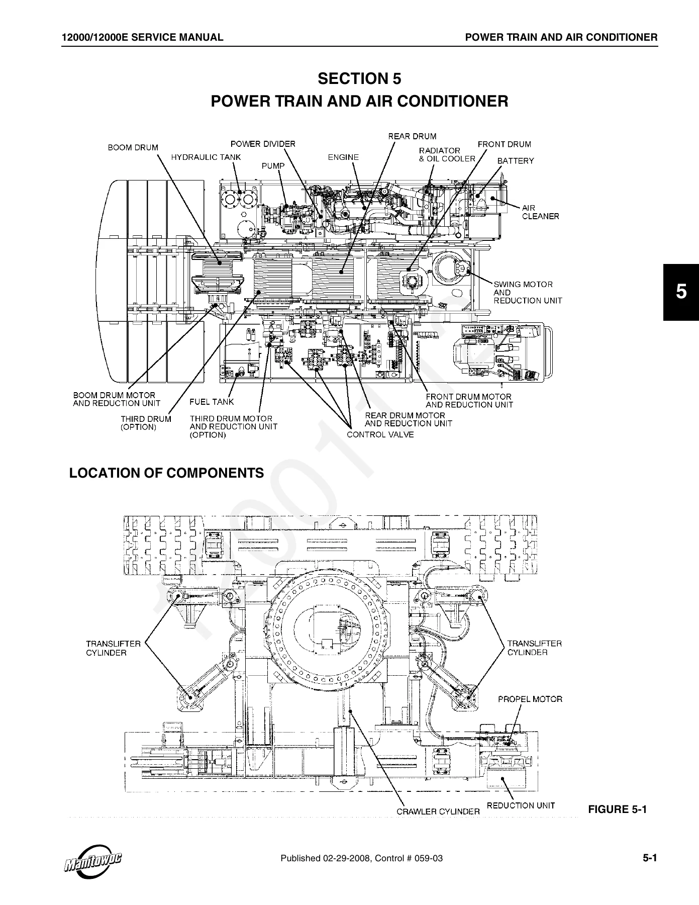
Manitowoc 12000 & 12000E Crane Service Manual (Tier 3 Engine) – PDF Download β€” PDF page 69 preview
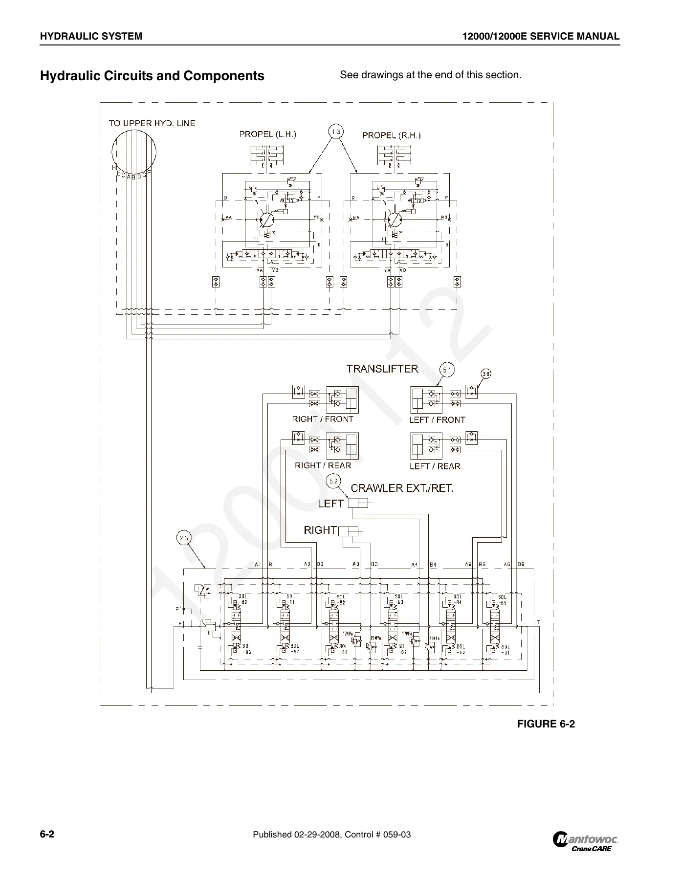
Manitowoc 12000 & 12000E Crane Service Manual (Tier 3 Engine) – PDF Download β€” PDF page 102 preview

Instant PDF Delivery

The Manitowoc 12000 & 12000E Crane Service Manual is delivered as an instant PDF download β€” no shipping, no waiting. Open it on a laptop, tablet or phone in the workshop or at the machine, search or scroll to the section you need, and print only the pages you want to take onto the job. The document is laid out in the same section-by-section structure Manitowoc uses, so you can jump straight to the system you are working on rather than reading cover to cover.


Reviews

There are no reviews yet.

Be the first to review “Manitowoc 12000 & 12000E Crane Service Manual (Tier 3 Engine) – PDF Download”

What Our Customers Say

β˜…β˜…β˜…β˜…β˜… Live reviews from customers
Loading customer reviews...
0
    0
    Your Cart
    Your cart is emptyReturn to Shop
    πŸ›’
    Recently Purchased
    πŸ•’ verified order