
★ TRUSTED BY 321,897+ PROFESSIONALS WORLDWIDE
🏒
Trusted Business
Verified & Licensed
πŸ›‘οΈ
Virus Free Files
100% Safe Downloads
πŸ”’
Secure Payment
SSL Protected
⚑
Instant Delivery
Available Immediately
Sale!

Mercury 115 135 150 175 OptiMax 150/175 Pro XS Service Manual 90-8M0057453

Original price was: $44.95.Current price is: $26.95.

733-page Mercury service manual for 115, 135, 150 and 175 2.5 Liter OptiMax outboards, including 150 Pro XS and 175 Pro XS, serial number 0G960500 and above. Covers specifications, maintenance, installation, ignition, charging and starting, fuel injection, oil injection, powerhead, cooling, power trim, troubleshooting and right-hand/left-hand gear housing service.

⚑
Instant PDF Download
Available immediately
πŸ’Ύ
Save to Your Device
Download & keep forever
πŸ›‘οΈ
Antivirus Scanned
100% virus-free
🌍
Trusted Worldwide
175,000+ customers

Description

Mercury 115 135 150 175 OptiMax 150/175 Pro XS Service Manual 90-8M0057453

The Mercury 115 135 150 175 OptiMax 150/175 Pro XS Service Manual 90-8M0057453 covers Mercury 2.5 Liter OptiMax outboards in 115, 135, 150 and 175 hp versions, including the 150 Pro XS and 175 Pro XS, for serial number 0G960500 and above. This 733-page service publication brings together specifications, maintenance, installation, electrical diagnosis, direct fuel injection service, oil injection, powerhead work, cooling, mid-section service, power trim, and both standard-rotation and counterrotation gear housing procedures. It is written around the actual system layouts and serial-number changes used across the covered engines, with service data, test values, component illustrations, troubleshooting information, removal and installation sequences, and torque specifications throughout.

File Details

  • Manual type: Service Manual
  • Brand: Mercury
  • Models: 115/135/150/150 Pro XS/175/175 Pro XS 2.5 Liter OptiMax
  • Serial coverage: 0G960500 and above
  • Document number: 90-8M0057453
  • Date: May 2011
  • Language: English
  • Pages: 733
  • Format: PDF

Engine and Service Coverage

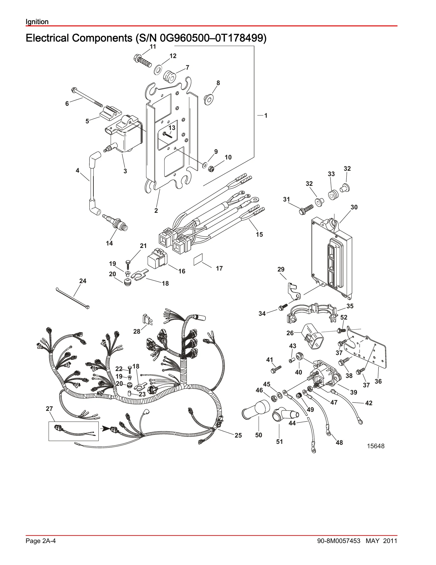
This manual separates procedures and component arrangements where the engine changed across production. Examples include electrical and ignition component layouts for serial ranges such as 0G960500-0T178499, 0T178500 through later ranges, and 1B490866 and above, plus later 175 Pro XS component views. That serial-specific organization is especially useful when working on ignition coils, electrical plates, fuses, sensors, fuel-system parts, powerhead components, and trim circuits because the manual shows the applicable configuration rather than treating every 2.5 Liter OptiMax as identical.

The specifications section gives core reference values before the repair chapters begin. The covered engines use a 2.5 liter (153 inΒ³), six-cylinder powerhead. Rated output is listed as 85.7 kW (115 hp), 100.8 kW (135 hp), 111.8 kW (150 hp), and 130.5 kW (175 hp). The manual provides idle and wide-open-throttle RPM ranges, Guardian RPM limits, direct fuel-injection pressures, air-compressor data, charging and starter specifications, cooling pressures and thermostat temperatures, power trim pressures, and gearcase ratios, capacities, backlash, runout, and pressure-test values. Maintenance information includes fuel and oil recommendations, spark-plug applications, battery requirements, lubrication points, water-pressure checks, and gearcase service data.

IMAGES PREVIEW

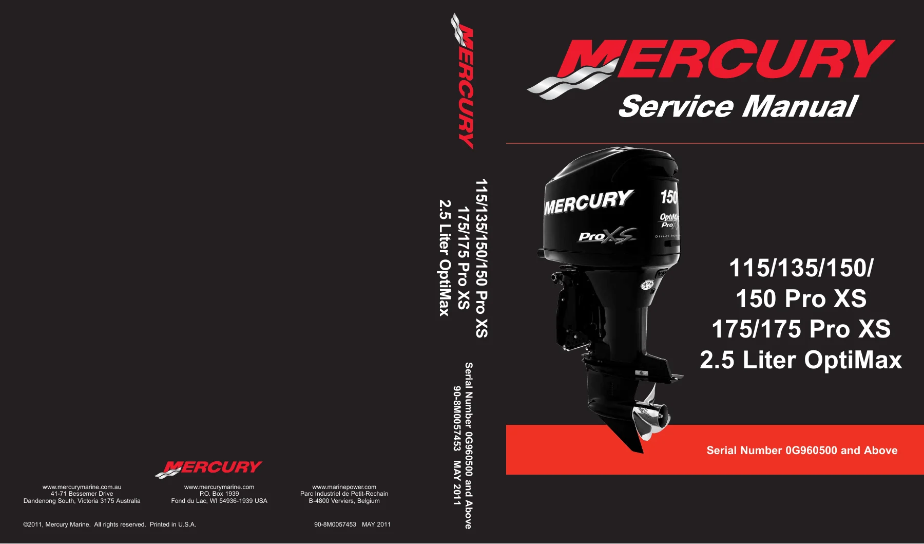
Mercury 115 135 150 175 OptiMax 150/175 Pro XS Service Manual 90-8M0057453 β€” PDF page 1 preview
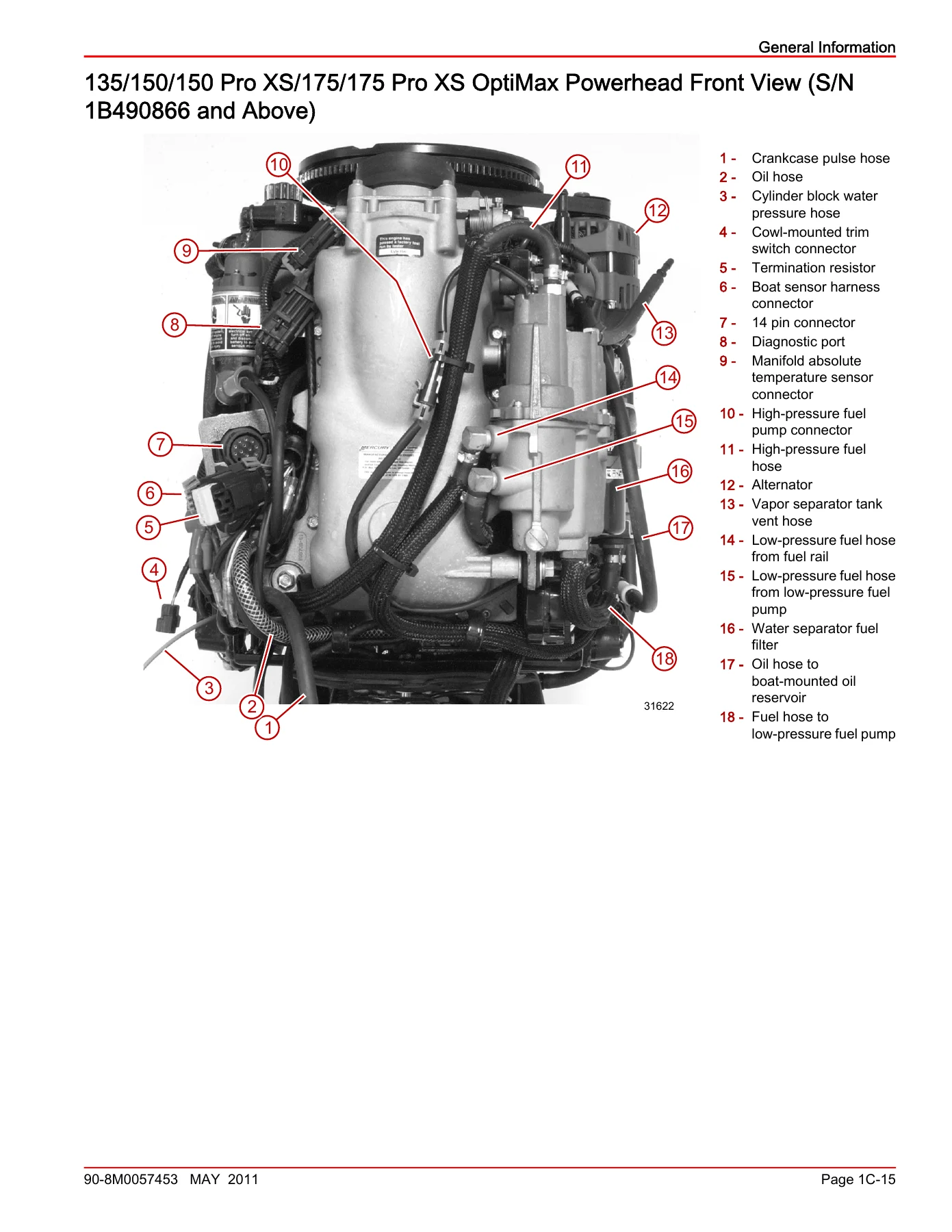
Mercury 115 135 150 175 OptiMax 150/175 Pro XS Service Manual 90-8M0057453 β€” PDF page 50 preview
Mercury 115 135 150 175 OptiMax 150/175 Pro XS Service Manual 90-8M0057453 β€” PDF page 89 preview

Chapters Covered

  • 1 – Important Information
    • Specifications – general, maintenance, ignition, charging and starting, fuel rail, fuel system, air compressor, powerhead, cooling, power trim and gearcase data
    • Maintenance – inspection schedule, cooling-system flushing, fuel filter, fuses, corrosion control, battery, propeller, spark plugs, compressor filter, alternator belt, lubrication, trim fluid, gearcase lubricant and storage
    • General Information – serial number location, powerhead views, performance conditions, submersion procedures, compression and cylinder leakage testing, power trim and tilt
    • Outboard Installation – mounting, steering, electrical and hose connections, shift and throttle cables, fuel and oil setup, oil pump priming, propeller installation and trim tab adjustment
  • 2 – Electrical
    • Ignition – specifications, ignition components, PCM, coils and coil drivers, crankshaft and throttle position sensors, temperature and MAP/MAT sensors, fuses and warning systems
    • Ignition troubleshooting – diagnosis with and without the Computer Diagnostic System, no-start, rough-running, speed-reduction and loss-of-spark conditions
    • Charging and Starting System – flywheel and alternator, alternator diagnosis, starter systems, solenoids, battery cable tests, battery service and key-switch tests
    • Timing, Synchronizing and Adjustments – crankshaft position sensor air gap, throttle cam, maximum throttle, throttle plate stop, TPS and idle-speed adjustments
  • 3 – Fuel System
    • Fuel Pump – fuel-system specifications, pump components and operation, anti-siphon valves, lift-pump vacuum testing, removal, disassembly, assembly and installation
    • Fuel Injection System – air compressor, fuel-system and fuel-rail specifications, air handler, vapor separator, fuel rails, air/fuel/water hoses and direct fuel-injection operation
    • Fuel Injection Diagnosis and Service – low- and high-pressure pump tests, air-compressor pressure test, VST service, regulators, tracker valve, direct injector tests, fuel-rail cleaning and air-compressor overhaul
    • Oil Injection – oil-system operation and output, hose routing, oil pump removal and installation, engine reservoir service, pump priming, remote tank connections and warning signals
    • Emissions – exhaust emission standards, HC/CO/NOx information, emissions reduction, responsibilities, EPA regulations, certification labels and service replacement decal procedures
  • 4 – Powerhead
    • Powerhead – cylinder block, end caps, exhaust manifold and plate, cylinder heads, crankshaft, pistons, connecting rods, reed blocks, bearings and thermostats
    • Removal and disassembly – dressed powerhead removal by serial range, harness and component removal, teardown, cleaning and inspection
    • Assembly and installation – crankshaft bearings, crankshaft, piston and connecting rod assembly, piston installation, crankcase cover, reed block, exhaust divider, cylinder heads, oil-hose routing and component installation
    • Cooling – temperature sensors, 2.5 Liter OptiMax water flow, thermostat tests, water-pressure checks, strainer, pressure relief valve, water-pressure sensor and water-pump inspection
  • 5 – Mid-Section
    • Clamp/Swivel Brackets and Driveshaft Housing – steering arm, transom bracket, driveshaft housing, exhaust tube, Dyna-Float suspension, shift linkage, disassembly and assembly
    • Power Trim Design I (Showa) – trim specifications, components, motor, hydraulic and electrical troubleshooting, trim sensors, test-gauge checks, cylinder service and complete trim assembly repair
    • Power Trim Design II (Oildyne) – three-ram components, hydraulic flow diagrams, leakage and pressure tests, electrical troubleshooting, trim and tilt cylinder service, motor/pump repair and system priming
  • 6 – Gear Housing
    • Right-Hand Standard Rotation Non-Ratcheting – gearcase specifications, driveshaft and propeller-shaft assemblies, bearings, shims and seals, water pump, carrier, pinion and gears
    • Standard-rotation setup and service – pinion depth, forward and reverse backlash, propeller-shaft assembly, water-pump assembly, pressure testing, installation and lubricant filling
    • Left-Hand Counterrotation Non-Ratcheting – left-hand propeller-shaft and bearing-carrier service, forward/reverse gear assemblies, driveshaft, pinion depth and backlash
    • Counterrotation setup and service – water-pump assembly, gear-housing pressure test, installation, speedometer tube installation and gear-lubricant filling

Taken as a whole, the Mercury 115 135 150 175 OptiMax 150/175 Pro XS Service Manual 90-8M0057453 is a complete service reference for the mechanical, electrical, fuel, lubrication, cooling, trim, installation and gearcase systems of the covered engines. The chapter structure moves from specifications and routine maintenance into system theory, testing, troubleshooting and component-level repair, so a technician can cross-check a symptom against the correct test value and then follow the relevant removal, inspection, assembly and installation procedure.

Complete PDF Bookmark Tree

Complete Bookmarks

The complete bookmarks in the β€œMercury 115 135 150 175 OptiMax 150/175 Pro XS Service Manual 90-8M0057453” are as follows:

cover
notice.pdf
Notice to Users of This Manualp. 2
Precautionsp. 2
Replacement Partsp. 3
Cleanliness and Care of Productp. 3
Manual Outlinep. 4
1ap. 6
Section 1A – Specificationsp. 6
Table of Contentsp. 6
General Specificationsp. 7
Maintenance Specificationsp. 8
Ignition Specificationsp. 8
Charging and Starting Specificationsp. 9
Fuel Rail Specificationsp. 10
Fuel System Specificationsp. 10
Air Compressor Specificationsp. 11
Powerhead Specificationsp. 12
Cooling System Specificationsp. 12
Power Trim Specifications (Showa)p. 12
Power Trim Specificationsp. 13
Gearcase Specificationsp. 13
115 OptiMax Propeller Information Chart Standard Rotationp. 14
135 OptiMax Propeller Information Chart Standard Rotationp. 15
150 OptiMax, 175 OptiMax, 150 Pro XS, 175 Pro XS Propeller Information Chart Standard Rotationp. 16
1Bp. 20
Section 1B – Maintenancep. 20
Table of Contentsp. 20
Maintenance Specificationsp. 21
Selecting Accessories for Your Outboardp. 21
EPA Emissions Regulationsp. 21
EPA Emissionsp. 22
Emission Certification Labelp. 22
Owner Responsibilityp. 22
Inspection and Maintenance Schedulep. 22
Before Each Usep. 22
After Each Usep. 22
Every 100 Hours of Use or Once Yearly, Whichever Occurs Firstp. 22
Before Periods of Storagep. 23
Flushing the Cooling Systemp. 23
Cleaning Care for Top Cowlp. 23
Cleaning and Waxing Procedurep. 23
Top Cowl Removal and Installationp. 23
Removalp. 23
Installationp. 24
Flywheel Cover Removal and Installationp. 24
Removalp. 24
Installationp. 24
Fuel Systemp. 24
Fuel Line Inspectionp. 24
Water Separating Fuel Filterp. 24
Steering Link Rod Fastenersp. 25
Fuse Replacement (S/N 1B490865 and Below)p. 25
Fuse Replacement (S/N 1B490866 and Above)p. 26
Corrosion Control Anodep. 26
Battery Inspectionp. 27
Battery Informationp. 27
Propeller Installationp. 28
Spark Plug Inspection and Replacementp. 29
Compressor Air Intake Filterp. 29
Removalp. 29
Installationp. 30
Alternator Belt Inspectionp. 30
Lubrication Pointsp. 30
Checking Power Trim Fluidp. 32
Gearcase Lubricationp. 32
Draining Gearcasep. 32
Gearcase Lubricant Capacityp. 33
Gearcase Lubricant Recommendationp. 33
Checking Lubricant Level and Refilling Gearcasep. 33
Submerged Outboardp. 33
Storage Preparationp. 33
Protecting Internal Engine Componentsp. 34
Protecting External Outboard Componentsp. 34
Gearcasep. 34
Positioning Outboard for Storagep. 34
Battery Storagep. 34
1cp. 36
Section 1C – General Informationp. 36
Table of Contentsp. 36
General Specificationsp. 37
Serial Number Locationp. 38
Model Year 2000 115/135/150 OptiMax Powerhead Front Viewp. 38
Model Year 2000 115/135/150 OptiMax Powerhead Starboard Viewp. 39
Model Year 2000 115/135/150 OptiMax Powerhead Port Viewp. 40
Model Year 2000 115/135/150 OptiMax Powerhead Top Viewp. 41
Model Year 2000 115/135/150 OptiMax Powerhead Aft Viewp. 42
Model Year 2001 135/150/175 OptiMax Powerhead Front View (S/N 0T178500–1B490865)p. 43
Model Year 2001 135/150/175 OptiMax Powerhead Starboard View (S/N 0T178500–1B490865)p. 45
Model Year 2001 135/150/175 OptiMax Powerhead Port View (S/N 0T178500–1B490865)p. 47
Model Year 2001 135/150/175 OptiMax Powerhead Top View (S/N 0T178500–1B490865)p. 48
Model Year 2001 135/150/175 OptiMax Powerhead Aft View (S/N 0T178500–1B490865)p. 49
135/150/150 Pro XS/175/175 Pro XS OptiMax Powerhead Front View (S/N 1B490866 and Above)p. 50
135/150/150 Pro XS/175/175 Pro XS OptiMax Powerhead Starboard View (S/N 1B490866 and Above)p. 51
135/150/150 Pro XS/175 OptiMax Powerhead Port View (S/N 1B490866 and Above)p. 53
135/150/150 Pro XS/175/175 Pro XS OptiMax Powerhead Top View (1B490866 and Above)p. 54
135/150/150 Pro XS/175/175 Pro XS OptiMax Powerhead Aft View (S/N 1B490866 and Above)p. 55
175 Pro XS OptiMax Powerhead Port View (S/N 1B516339 and Above)p. 56
Conditions Affecting Performancep. 57
Weatherp. 57
Weight Distribution (Passengers and Gear) Inside the Boatp. 57
Bottom of Boatp. 57
Water Absorptionp. 58
Cavitationp. 58
Ventilationp. 58
Detonationp. 58
Following Complete Submersionp. 58
Saltwater Submersionp. 58
Submerged While Runningp. 58
Submerged Engine (Fresh Water)p. 58
Compression Checkp. 59
Cylinder Leakage Testingp. 60
Analysisp. 60
Painting Proceduresp. 60
Propellersp. 60
Gear Housingp. 60
Shipping of Hazardous Material (HazMat) and Engine/Components Containing Hazardous Materialp. 61
Outboard Service Bulletin 2008-07p. 61
Overview of Regulationsp. 61
Overview of Training Requirementsp. 61
Shipping of Complete Engines and Major Assembliesp. 62
More Information on Hazardous Materialp. 62
Decal Applicationp. 62
Decal Removalp. 62
Application Instructionsp. 62
Tools Requiredp. 62
Temperaturep. 62
Surface Preparationp. 62
Power Trim and Tiltp. 63
Power Trim Operationp. 63
Tilting Operationp. 64
Manual Tiltingp. 64
Shallow Water Operationp. 64
Auxiliary Tilt Switchp. 64
1dp. 66
Section 1D – Outboard Installationp. 66
Table of Contentsp. 66
Installation Specificationsp. 67
Important Informationp. 67
Before Starting the Enginep. 67
Fuel Requirementsp. 68
Oil Recommendationp. 68
Avoiding Fuel Flow Restrictionp. 68
Electric Fuel Pumpp. 68
Boat Horsepower Capacityp. 68
Start in Gear Protectionp. 68
Selecting Accessories for Your Outboardp. 68
Fuel Tanksp. 69
Portable Fuel Tankp. 69
Permanent Fuel Tankp. 69
EPA Pressurized Portable Fuel Tank Requirementsp. 69
Fuel Demand Valve (FDV) Requirementp. 69
Lifting the Outboardp. 69
Steering Cable – Starboard Side Routed Cablep. 70
Steering Link Rod Fastenersp. 70
Determining Recommended Outboard Mounting Heightp. 71
Drilling Outboard Mounting Holesp. 71
Fastening the Outboard to the Transomp. 72
Mounting Boltsp. 72
Checking Boat Transom Constructionp. 73
Electrical, Hoses, and Control Cablesp. 74
Four Function Warning Gauge Harness (Model Year 2000 Only)p. 74
Front Clamp Disassemblyp. 75
Remote Wiring Harnessp. 75
Battery Cable Size for Outboard Modelsp. 75
Battery Cable Connectionsp. 77
Single Outboardp. 77
Dual Outboardsp. 77
Fuel Hose Connectionp. 77
Fuel Hose Sizep. 77
Oil Hose Connectionsp. 77
Speedometer Tubing Connection (Models without SmartCraft Gauges)p. 77
Water Pressure Tubing Connection (Models without SmartCraft Gauges)p. 78
Shift and Throttle Cablep. 78
Counterrotation Outboardsp. 78
Installing the Shift Cablep. 79
Locating the Center Point of the Shift Cablep. 79
Throttle Cable Installationp. 80
Front Clamp Reassemblyp. 81
Filling the Fuel Systemp. 81
Oil Injection Setupp. 82
Oil Recommendationp. 82
Filling Remote Oil Tankp. 82
Filling Engine Mounted Oil Reservoir Tankp. 82
Priming the Oil Injection Pumpp. 82
Purging Air from the Engine Oil Tankp. 83
Trim In Pin (Three-Ram)p. 83
Propeller Installationp. 84
Trim Tab Adjustmentp. 85
2ap. 86
Section 2A – Ignitionp. 86
Table of Contentsp. 86
Ignition Specificationsp. 87
Electrical Components (S/N 0G960500–0T178499)p. 89
Electrical Components (S/N 0T178500–1B226999)p. 93
115/135/150/175 Coil Plate (S/N 1B490865 and Below)p. 97
115/135/150/175 Electrical Plate (S/N 1B490865 and Below)p. 99
135/150/150 Pro XS/175/175 Pro XS Electrical Plate (S/N 1B490866 and Above)p. 103
135/150/150 Pro XS/175/175 Pro XS Coil Plate (S/N 1B490866 and Above)p. 105
Troubleshooting without a Computer Diagnostic System (CDS)p. 107
Troubleshooting with the Computer Diagnostic System (CDS)p. 107
Troubleshooting Guidep. 108
Theory of Operation – Internal Ignition Coil Driver Modelsp. 110
Theory of Operation – External Ignition Coil Driver Modelsp. 110
Fusesp. 111
Propulsion Control Module (PCM)p. 112
Main Power Relay (MPR)p. 112
Flywheelp. 112
Ignition Coilsp. 113
Ignition Coil Ohms Test (S/N 0G960500–1B490865)p. 113
Ignition Coil Ohms Test (S/N 1B490866 and Above)p. 114
Coil Drivers (S/N 1B490865 and Below)p. 115
Electronic Spark Trigger Circuitp. 115
Wiring Harness Testsp. 115
Coil Driver Testsp. 117
Resistance Testp. 117
Crankshaft Position Sensorp. 117
Throttle Position Sensor (TPS)p. 118
Cylinder Head Temperature Sensor (Model Year 2000)p. 119
Cylinder Head Temperature Sensor Testp. 119
Air Compressor Cylinder Head Temperature Sensor (Model Year 2000)p. 119
Air Compressor Cylinder Head Temperature Sensor Testp. 120
Cylinder Head Coolant Temperature Sensor (S/N 0T178500–0T800999)p. 121
Cylinder Head Coolant Temperature Sensor Testp. 121
Cylinder Head Coolant Temperature Sensor Removalp. 121
Cylinder Head Coolant Temperature Sensor Installationp. 121
Cylinder Head Coolant Temperature Sensor (S/N 0T801000 and Above)p. 122
Cylinder Head Coolant Temperature Sensor Testp. 122
Cylinder Head Coolant Temperature Sensor Removalp. 123
Cylinder Head Coolant Temperature Sensor Installationp. 123
Manifold Absolute Pressure (MAP) Sensorp. 123
Manifold Absolute Pressure Sensor Testp. 123
Manifold Intake Air Temperature (MAT) Sensorp. 124
Manifold Intake Air Temperature Sensor Testp. 124
Shift Position Switchp. 125
Ignition Components Removal and Installationp. 125
Flywheel Cover Removal and Installationp. 125
Flywheel Cover Removalp. 125
Flywheel Cover Installationp. 125
Propulsion Control Module (PCM) Removal and Installationp. 126
PCM Removalp. 126
PCM Installationp. 126
Ignition Coil Removal and Installation (S/N 0G960500–0T178499)p. 127
Ignition Coil Removalp. 127
Ignition Coil Installationp. 127
Ignition Coil and Ignition Coil Driver Removal and Installation (S/N 0T178500–1B490865)p. 128
Ignition Coil and Ignition Coil Driver Removalp. 128
Ignition Coil Driver and Ignition Coil Installationp. 128
Ignition Coil Removal and Installation (S/N 1B490866 and Above)p. 129
Ignition Coil Removalp. 129
Ignition Coil Installationp. 130
Crankshaft Position Sensor (CPS)p. 130
Crankshaft Position Sensor Removal (S/N 0G960500–0T178499)p. 130
Crankshaft Position Sensor Installationp. 130
Crankshaft Position Sensor Removal (S/N 0T178500 and Above)p. 131
Crankshaft Position Sensor Installationp. 131
Throttle Position Sensor (TPS)p. 132
Throttle Position Sensor Removalp. 132
Throttle Position Sensor Installationp. 132
Shift Position Switchp. 133
Shift Position Switch Removalp. 133
Shift Position Switch Installationp. 133
Guardian Protection Systemp. 133
Guardian System Activationp. 134
Engine Overspeed Protection Systemp. 134
Warning Horn Signalsp. 134
2bp. 136
Section 2B – Charging and Starting Systemp. 136
Table of Contentsp. 136
Charging and Starting Specificationsp. 137
Flywheel/Alternatorp. 139
Starter Motor (S/N 0G960500–0T178499)p. 141
Starter Motor (S/N 0T178500 and Above)p. 143
Wire Color Code Abbreviationsp. 145
Charging System Components (S/N 0T598999 and Below)p. 145
Descriptionp. 145
Precautionsp. 145
Flywheel Removal and Installationp. 146
Removalp. 146
Installationp. 147
Alternator Systemp. 147
Alternator Descriptionp. 147
Diagnosis of Alternator System on the Enginep. 148
Alternator System Circuitry Testp. 149
Output Circuitp. 149
Sensing Circuitp. 150
Excitation Circuitp. 150
Alternator Removal and Installationp. 151
Removalp. 151
Installationp. 153
Belt Tensioner Removal and Installationp. 155
Removalp. 155
Installationp. 156
Starter Systemp. 157
Starter Motor Amp Drawp. 157
Starter System Descriptionp. 157
Starting System Componentsp. 158
Battery Cable Testp. 158
Original Battery Cable Length and Gauge Shipped with Enginep. 159
Battery Cable Size for Outboard Modelsp. 159
Start Solenoid Testp. 160
Starter Circuit Troubleshooting (Centrifugal Bendix)p. 162
Starter Removal and Installation (Centrifugal Bendix)p. 164
Removalp. 164
Installationp. 165
Starter Disassembly (Centrifugal Bendix)p. 166
Testing the Starter Armature and End Capp. 168
Armature Test for Shortsp. 168
Armature Test for Groundp. 168
Checking Positive Brushes and Terminalp. 169
Testing Negative Brushes for Groundp. 169
Starter Assembly (Centrifugal Bendix)p. 169
Starter Circuit Troubleshooting (Solenoid Driven Bendix)p. 171
Solenoid Driven Bendix Starter Diagramp. 172
Troubleshooting Chartp. 172
Starter Removal and Installation (Solenoid Driven Bendix) (S/N 0T178500–1B417701)p. 174
Starter Removalp. 174
Starter Installationp. 176
Starter Removal and Installation (S/N 1T801000 and Above)p. 178
Starter Removalp. 178
Starter Installationp. 179
Starter Circuit Troubleshooting (S/N 1B417702 and Above)p. 180
Starter Circuit Troubleshooting (S/N 1B417702 and Above)p. 181
Starter Circuit Troubleshooting (S/N 1B227000–1B417701)p. 184
Starter Circuit Troubleshooting (S/N 1T801000–1B226999)p. 187
Starter Disassembly (Solenoid Driven Bendix)p. 190
Pinion Gear Removalp. 190
Starter Assembly (Solenoid Driven Bendix)p. 191
Pinion Gear Installationp. 191
Solenoid Installationp. 192
Batteryp. 194
Replacement Partsp. 194
Recommended Batteryp. 194
Battery Precautionsp. 194
Charging a Discharged Batteryp. 195
Winter Storage of Batteriesp. 195
Commander 2000 Key Switchp. 195
Key Switch Testp. 196
Three Position Key Switchp. 196
Four Position Key Switchp. 197
2cp. 200
Section 2C – Timing, Synchronizing, and Adjustmentsp. 200
Table of Contentsp. 200
Crankshaft Position Sensor (S/N 0T178499 and Below)p. 201
Throttle Cam Adjustmentp. 201
Maximum Throttlep. 202
Throttle Plate Stop Screwp. 204
Throttle Position Sensor (TPS) Adjustmentp. 204
Idle Speed Adjustment (All Models)p. 205
3ap. 206
Section 3A – Fuel Pumpp. 206
Table of Contentsp. 206
Fuel System Specificationsp. 207
Fuel Pump Componentsp. 209
Fuel Pump Description/Operationp. 211
Anti-Siphon Valvesp. 211
Testing Fuel Lift Pump Vacuump. 211
Fuel Pump Removal and Disassemblyp. 212
Fuel Pump Assembly and Installationp. 213
3bp. 216
Section 3B – Fuel Injection Systemp. 216
Table of Contentsp. 216
Air Compressor Specificationsp. 217
Fuel System Specificationsp. 217
Fuel Rail Specificationsp. 218
Air Handler and Flywheel Cover (S/N 0T178499 and Below)p. 223
Air Handler and Flywheel Cover (S/N 0T178500 and Above)p. 225
Air Handler and Flywheel Cover 150 Pro XSp. 227
Air Handler Components (S/N 0G960500 and Above)p. 229
Vapor Separator Components (S/N 0T800999 and Below)p. 231
Vapor Separator Components (S/N 0T801000 and Above)p. 233
Fuel Rail Components (S/N 0T178499 and Below)p. 235
Fuel Rail Components (S/N 0T178500 and Above)p. 237
Air Hosesp. 239
Fuel Hosesp. 241
Water Hoses (Design 1)p. 243
Water Hoses (Design 2)p. 245
Water Hoses (175 Pro XS)p. 247
Air Compressor Components (S/N 0T178499 and Below)p. 249
Air Compressor Components (S/N 0T178500 and Above)p. 251
DFI Operationp. 255
Air Inductionp. 255
Air Compressor Systemp. 255
Fuelp. 255
Oilp. 255
Electricalp. 255
Operationp. 256
Electric Fuel Pump Pressure Testsp. 256
Low-Pressure Electric Fuel Pump Test (Boost Pump)p. 256
High-Pressure Electric Fuel Pumpp. 257
Air Compressor Pressure Testp. 258
Vapor Separator Tankp. 258
VST Removalp. 258
VST Disassemblyp. 261
VST Assemblyp. 265
VST Installationp. 268
Fuel Railp. 271
Fuel Pressure Regulatorp. 271
Fuel Pressure Regulator Cutawayp. 272
Air Pressure Regulatorp. 273
Tracker Valvep. 273
Fuel Rail Removalp. 275
Direct Injector Removalp. 278
Direct Injector Testsp. 278
Direct Injector Leak Testp. 278
Direct Injector Ohm Testp. 279
Direct Injector Pintel Movement Testp. 280
Fuel Pressure Regulator Removalp. 282
Air Pressure Regulator Removal (S/N 0T178499 and Below)p. 282
Air Pressure Regulator Removal (S/N 0T178500 and Above)p. 284
Tracker Valve Removalp. 284
Fuel Rail Cleaningp. 284
Tracker Valve Installationp. 285
Air Pressure Regulator Installation (S/N 0T178500 and Above)p. 285
Air Pressure Regulator Installation (S/N 0G960500–0T178499)p. 286
Fuel Pressure Regulator Installationp. 287
Fuel Rail Installationp. 288
Air Compressorp. 290
Air Compressor Removalp. 290
Air Compressor Disassemblyp. 294
Air Compressor Assemblyp. 295
Air Compressor Installationp. 298
Air Plenump. 301
Air Plenum Removalp. 301
Reed Block Assembly Removalp. 305
Air Temperature Sensor Removalp. 306
Throttle Body Assembly Removalp. 306
Air Plenum Assembly and Installationp. 306
3cp. 312
Section 3C – Oil Injectionp. 312
Table of Contentsp. 312
Oil System Operationp. 313
Oil Pump Outputp. 313
Oil System Hose Installation (S/N 0T178499 and Below)p. 314
Oil System Hose Installation (S/N 0T178500 and Above)p. 315
Oil Pump Removal and Installation (S/N 1B490865 and Below)p. 316
Oil Pump Removalp. 316
Oil Pump Installationp. 316
Oil Pump Removal and Installation (S/N 1B490866 and Above)p. 316
Oil Pump Removalp. 316
Oil Pump Installationp. 317
Engine Oil Reservoir Removal and Installationp. 317
Removalp. 317
Installationp. 319
Priming the Oil Injection Pumpp. 320
Method 1 – Shift Switch Activation Primep. 320
Method 2 – Computer Diagnostic System Break-in Clock Resetp. 321
Method 3 – Computer Diagnostic System Oil Pump Primep. 321
Remote Oil Tank Hose Connectionsp. 321
Filling the Oil Tanksp. 321
Purging Air from the Engine Oil Reservoir and Remote Oil Hosep. 322
Warning Horn Signalsp. 322
3dp. 324
Section 3D – Emissionsp. 324
Table of Contentsp. 324
Exhaust Emission Standardsp. 325
What Are Emissions?p. 325
Hydrocarbons – HCp. 325
Carbon Monoxide – COp. 325
Oxides of Nitrogen – NOxp. 325
Controlling Emissionsp. 325
Stoichiometric (14.7:1) Air/Fuel Ratiop. 325
Outboard Hydrocarbon Emissions Reductionp. 326
Emissions Informationp. 326
Models Affectedp. 326
Manufacturer's Responsibilityp. 326
Dealer Responsibilityp. 326
Owner Responsibilityp. 326
EPA Emission Regulationsp. 327
Manufacturer's Certification Labelp. 327
Service Replacement EPA Decalp. 327
Removalp. 327
Date Code Identificationp. 328
Installationp. 328
4ap. 330
Section 4A – Powerheadp. 330
Table of Contentsp. 330
Powerhead Specificationsp. 331
115/135/150/150 Pro XS/175 Cylinder Block and End Capsp. 335
175 Pro XS Cylinder Block and End Capsp. 339
Exhaust Manifold and Exhaust Platep. 343
Cylinder Headp. 347
115/135/150/150 Pro XS/175 Crankshaft, Pistons, and Connecting Rodsp. 349
175 Pro XS Crankshaft, Pistons, and Connecting Rodsp. 351
Dressed Powerhead Removalp. 353
Dressed Powerhead Removal (S/N 0G960500–1B226999)p. 353
Dressed Powerhead Removal (S/N 1B227000 and Above)p. 357
Powerhead Component Removal (S/N 1B227000–1B490865)p. 361
Wire Harness Removalp. 361
Removing Powerhead Componentsp. 368
Powerhead Component Removal (S/N 1B490866 and Above)p. 379
Ignition Coil Plate and Wire Harness Removalp. 379
Removing Powerhead Componentsp. 385
Powerhead Disassemblyp. 394
Lower Crankshaft Ball Bearing Removalp. 401
Cleaning and Inspectionp. 402
Cylinder Block and Crankcase Coverp. 402
Special Service Informationp. 403
Grooves in the Cylinder Block Caused by Crankshaft Sealing Ringsp. 403
Cylinder Boresp. 403
Honing Procedurep. 403
Pistons and Piston Ringsp. 404
Cleaning Piston Ring Groovesp. 404
Measuring Pistonp. 404
Cylinder Heads and Exhaust Divider Platep. 404
Crankshaftp. 405
Crankshaft and End Cap Bearingsp. 405
Connecting Rodsp. 406
Reed Block Assemblyp. 408
End Bearing Bleed Systemp. 408
Thermostatp. 408
Thermostat Measurement Testp. 408
Powerhead Assemblyp. 409
Powerhead Preassembly Cleaning Recommendationsp. 409
Crankshaft Bearings Installationp. 409
Crankshaft Installationp. 413
Before Installing a New Crankshaftp. 413
Installing the New Crankshaftp. 413
Piston and Connecting Rod Assemblyp. 414
Piston and Piston Ring Combinationsp. 416
Piston Installationp. 416
Crankcase Cover Installationp. 419
Reed Block Assemblyp. 420
Reed Block Adapter Plate Assemblyp. 421
Exhaust Divider Assemblyp. 421
Cylinder Head Installationp. 423
Starboard Side Oil Hose Routing (S/N 0T178499 and Above)p. 425
Port Side Oil Hose Routing (S/N 0T178499 and Above)p. 426
Powerhead Component Installation (S/N 1B227000–1B417701)p. 427
Installing Powerhead Componentsp. 427
Wire Harness Installationp. 442
Powerhead Component Installation (S/N 1B417702 and Above)p. 450
Installing Powerhead Componentsp. 450
Ignition Coil Plate and Wire Harness Installationp. 465
4bp. 474
Section 4B – Coolingp. 474
Table of Contentsp. 474
Cooling System Specificationsp. 475
Temperature Sensor Location and Functionp. 476
Temperature Sensorsp. 476
4 and 2 Wire Temperature Sensorp. 477
2 Pin Connector Cylinder Head Temperature Sensorp. 478
2.5 Liter OptiMax Water Flowp. 479
Descriptionp. 479
Troubleshootingp. 480
Thermostat Testp. 480
Water Pressure Checkp. 480
Cooling Water Strainerp. 481
Pressure Relief Valvep. 481
Water Pressure Sensorp. 482
Water Pump Cleaning and Inspectionp. 483
Problem Diagnosisp. 484
5ap. 486
Section 5A – Clamp/Swivel Brackets and Driveshaft Housingp. 486
Table of Contentsp. 486
Swivel Bracket and Steering Arm Componentsp. 489
Transom Bracket Componentsp. 491
Driveshaft Housing and Exhaust Tube Componentsp. 493
Driveshaft Housing and Dyna-Float Suspension Removal and Disassemblyp. 497
Powerhead and Lower Unit Removalp. 497
Removal and Disassemblyp. 497
Transom/Swivel Bracketp. 500
Disassemblyp. 500
Swivel Bracket/Pin Disassemblyp. 502
Swivel Bracket/Pin Assemblyp. 503
Transom/Swivel Bracket Assemblyp. 504
Driveshaft Housing and Dyna-Float Suspension Assembly and Installationp. 506
Shift Linkage Assemblyp. 510
Powerhead and Lower Unit Installationp. 511
5bp. 512
Section 5B – Power Trim – Design I (Showa)p. 512
Table of Contentsp. 512
Power Trim Specifications (Showa)p. 513
Power Trim Componentsp. 515
Power Trim Motorp. 519
Power Trim – General Informationp. 519
Power Trim Characteristicsp. 519
Trimming Outboard Up/Outp. 519
Trimming Outboard Down/Inp. 520
Trailering Outboardp. 520
Tilting Outboard Manuallyp. 520
Trim In Angle Adjustmentp. 521
Striker Plate Replacementp. 521
Anode Platep. 521
Trim Indicator Gaugep. 522
Check, Fill, and Purge – Power Trim Systemp. 522
To Check:p. 522
To Fill:p. 523
To Purge:p. 523
Hydraulic System Troubleshootingp. 523
Troubleshootingp. 523
Preliminary Checksp. 523
Condition/Problemp. 524
Problem/Solutionp. 524
Three Ram Trim System Troubleshooting Diagramp. 525
Electrical System Troubleshootingp. 525
Wire Color Code Abbreviationsp. 525
General Checksp. 525
Condition/Problemp. 526
Problem/Solutionp. 526
Trim Circuitp. 526
Power Trim Relay Test Procedurep. 526
Power Trim Electrical Circuit (S/N 0G960500–1B226999) (Model Year 2000–2005)p. 528
Power Trim Electrical Circuit (S/N 1B227000–1B490865)p. 529
Power Trim Electrical Circuit (S/N 1B490866 and Above)p. 530
Troubleshooting the Trim Electrical Circuitp. 531
Up Circuit Inoperativep. 531
Down Circuit Inoperativep. 531
Up and Down Circuits (All Circuits Inoperative)p. 531
Trim Position Sensorp. 532
Digital Trim Sensorp. 532
Locationp. 532
Trim Position Wiringp. 532
Troubleshooting the Digital Trim Sensorp. 532
Analog Trim Sender Testp. 533
Analog Trim Sensor Wiring Diagramp. 533
Trim Indicator Gauge Needle Adjustmentp. 534
Testing the Showa Power Trim System with a Test Gaugep. 534
Tilt Pressure Checkp. 534
Down Pressure Checkp. 536
Power Trim Assembly Removal and Installation Proceduresp. 539
Power Trim Assembly Removalp. 539
Power Trim Assembly Installation
Trim Cylinderp. 543
Trim Rod Removalp. 543
Cleaning and Inspection – Trim Rods and End Capsp. 544
Trim Rod End Cap Sealp. 545
Trim Rod Installationp. 545
Tilt Cylinderp. 546
Tilt Cylinder Componentsp. 546
Tilt Cylinder Components – Black Anodized Capp. 547
Tilt Ram Removalp. 547
Power Trim System Removed from Outboardp. 547
Cleaning and Inspectionp. 548
Disassemblyp. 548
Memory Piston Removalp. 550
Scraper Seal Replacementp. 552
Tilt Cylinder Assemblyp. 552
Tilt Cylinder Assembly Installationp. 554
Priming the Power Trim Systemp. 555
Power Trim Disassemblyp. 556
Power Trim Removalp. 556
Trim Motor Removalp. 557
Power Trim Pump Removalp. 557
Motor and Electrical Tests/Repairp. 558
Trim Pump Motor Testp. 558
Motor Disassemblyp. 559
Armature Testsp. 559
Test for Shortsp. 559
Test for Groundp. 559
Checking and Cleaning Commutatorp. 560
Field Testsp. 560
Motor Repairp. 560
Removalp. 560
Disassemblyp. 560
Cleaning and Inspectionp. 560
Brush Replacementp. 561
End Cap Inspectionp. 562
Reassemblyp. 563
Power Trim Assemblyp. 565
Power Trim Pump Installationp. 565
Trim Motor Installationp. 566
Reservoir Cover Installationp. 567
5cp. 570
Section 5C – Power Trim – Design II (Oildyne)p. 570
Table of Contentsp. 570
Power Trim Specificationsp. 571
Three Ram Power Trim Componentsp. 573
Power Trim – General Informationp. 575
Power Trim Characteristicsp. 575
Trimming Outboard Up/Outp. 575
Trimming Outboard Down/Inp. 575
Trailering Outboardp. 575
Tilting Outboard Manuallyp. 576
Trim In Angle Adjustmentp. 576
Striker Plate Replacementp. 577
Anode Platep. 577
Trim Indicator Gaugep. 577
Check, Fill, and Purge – Power Trim Systemp. 577
To Check:p. 577
To Fill:p. 578
To Purge:p. 578
Power Trim Flow Diagramsp. 579
Trim Up Circuitp. 579
Tilt Circuitp. 581
Trim Down Circuitp. 583
Trail Over and Shock Absorberp. 585
Trail Over Systemp. 586
Shock Systemp. 586
Manual Tiltp. 587
Manual Tilt Systemp. 588
Reverse Operationp. 588
Hydraulic System Troubleshootingp. 588
Power Tilt Leakage Test Procedurep. 588
Method 1p. 588
Method 2p. 589
Troubleshootingp. 589
Preliminary Checksp. 589
Condition/Problemp. 589
Problem/Solutionp. 589
Three Ram Trim System Troubleshooting Diagramp. 590
Electrical System Troubleshootingp. 591
Wire Color Code Abbreviationsp. 591
General Checksp. 591
Condition/Problemp. 591
Problem/Solutionp. 591
Trim Circuitp. 591
Power Trim Relay Test Procedurep. 592
Power Trim Electrical Circuit (S/N 0G960500–1B226999) (Model Year 2000–2005)p. 593
Power Trim Electrical Circuit (S/N 1B227000–1B490865)p. 594
Power Trim Electrical Circuit (S/N 1B490866 and Above)p. 595
Troubleshooting the Trim Electrical Circuitp. 596
Up Circuit Inoperativep. 596
Down Circuit Inoperativep. 596
Up and Down Circuits (All Circuits Inoperative)p. 596
Trim Position Sensorp. 597
Digital Trim Sensorp. 597
Locationp. 597
Trim Position Wiringp. 597
Troubleshooting the Digital Trim Sensorp. 597
Analog Trim Sensor Wiring Diagramp. 598
Analog Trim Sender Testp. 598
Trim Indicator Gauge Needle Adjustmentp. 599
Testing the Power Trim System with a Test Gaugep. 599
Tilt Pressure Checkp. 599
Down Pressure Checkp. 601
Power Trim Assembly Removal and Installation Proceduresp. 604
Power Trim Assembly Removalp. 604
Power Trim Assembly Installation
Trim Cylinderp. 608
Trim Rod Removalp. 608
Cleaning and Inspection – Trim Rods and End Capsp. 609
Trim Rod End Cap Sealp. 610
Trim Rod Installationp. 610
Tilt Cylinderp. 611
Tilt Cylinder Components – Black Anodized Capp. 611
Tilt Ram Removalp. 611
Power Trim System Removed from Outboardp. 611
Cleaning and Inspectionp. 612
Disassemblyp. 612
Memory Piston Removalp. 614
Scraper Seal Replacementp. 614
Tilt Cylinder Assemblyp. 614
Tilt Ram Assembly Installationp. 617
Priming the Power Trim Systemp. 618
Power Trim Disassemblyp. 618
Power Trim Removalp. 618
Trim Motor Removalp. 620
Pump and Component Removalp. 620
Motor and Electrical Tests/Repairp. 622
Trim Pump Motor Testp. 622
Motor Disassemblyp. 623
Armature Testsp. 623
Test for Shortsp. 623
Test for Groundp. 624
Checking and Cleaning Commutatorp. 624
Field Testsp. 624
Motor Repairp. 624
Power Trim Assemblyp. 625
Reassemblyp. 625
Reassembly – Motor and Pumpp. 626
6ap. 630
Section 6A – Right-Hand (Standard Rotation) Non-Ratchetingp. 630
Table of Contentsp. 630
Gearcase Specificationsp. 631
Gear Housing (Driveshaft)p. 637
Gear Housing (Propeller Shaft Right-Hand Rotation)p. 641
General Service Recommendationsp. 643
Bearingsp. 643
Shimsp. 643
Sealsp. 643
Gearcase Removalp. 643
Gearcase Service Inspectionp. 645
Draining and Inspecting Gear Housing Lubricantp. 645
Propeller Shaft Inspectionp. 645
Water Pump Removal and Disassemblyp. 646
Bearing Carrier and Propeller Shaft Removalp. 648
Shift Shaft Inspectionp. 649
Bearing Carrier Disassemblyp. 649
Propeller Shaft Inspection and Disassemblyp. 651
Propeller Shaft Inspectionp. 651
Propeller Shaft Disassemblyp. 651
Pinion Gear and Driveshaft Removalp. 653
Cleaning and Inspectionp. 654
Forward Gear Disassemblyp. 655
Cleaning and Inspectionp. 656
Gear Housing Inspectionp. 656
Pinion Bearing Installationp. 657
Bearing Carrier Assemblyp. 658
Forward Gear Assemblyp. 660
Forward Gear Bearing Race Assemblyp. 661
Driveshaft Assemblyp. 662
Pinion Gear Depth and Forward Gear Backlashp. 664
Pinion Gear Depthp. 664
Forward Gear Backlashp. 666
Propeller Shaft Assemblyp. 668
Reverse Gear Backlash (Standard Rotation)p. 671
Water Pump Assemblyp. 673
Gear Housing Pressure Testp. 675
Gear Housing Installationp. 675
Speedometer Tube Installation (Early Models)p. 677
Gear Lubricant Filling Instructionsp. 677
6bp. 680
Section 6B – Left-Hand (Counterrotation) Non-Ratchetingp. 680
Table of Contentsp. 680
Gearcase Specificationsp. 681
Gear Housing (Driveshaft)p. 687
Gear Housing (Propeller Shaft Left-Hand Rotation)p. 691
General Service Recommendationsp. 693
Bearingsp. 693
Shimsp. 693
Sealsp. 693
Gearcase Removalp. 693
Gearcase Service Inspectionp. 695
Draining and Inspecting Gear Housing Lubricantp. 695
Left-Hand Rotation Propeller Shaft Inspectionp. 695
Water Pump Removal and Disassemblyp. 696
Bearing Carrier and Propeller Shaft Removal (Left-Hand Rotation)p. 698
Shift Shaft Inspectionp. 699
Bearing Carrier Disassembly (Left-Hand Rotation)p. 699
Propeller Shaft Inspection and Disassemblyp. 700
Propeller Shaft Inspectionp. 700
Propeller Shaft Disassemblyp. 701
Forward Gear and Bearing Adapter Disassemblyp. 702
Pinion Gear and Driveshaft Removalp. 704
Cleaning and Inspectionp. 705
Reverse Gear Removal and Disassemblyp. 706
Cleaning and Inspectionp. 706
Gear Housing Inspectionp. 707
Pinion Bearing Installationp. 708
Forward Gear Bearing Adapter and Bearing Carrier Assemblyp. 709
Forward Gear Bearing Adapter Assemblyp. 709
Bearing Carrier Assemblyp. 709
Reverse Gear and Bearing Adapter Assemblyp. 710
Reverse Gear Assemblyp. 710
Bearing Adapter Assemblyp. 711
Reverse Gear Bearing Adapter and Gear Installationp. 711
Driveshaft Assemblyp. 713
Pinion Gear Depth and Reverse Gear Backlashp. 715
Pinion Gear Depthp. 715
Reverse Gear Backlashp. 718
Forward Gear Backlashp. 719
Propeller Shaft, Forward Gear Bearing Adapter, and Bearing Carrier Assemblyp. 722
Propeller Shaft Assemblyp. 722
Forward Gear Bearing Adapterp. 724
Bearing Carrier Assemblyp. 726
Water Pump Assemblyp. 728
Gear Housing Pressure Testp. 730
Left-Hand (Counterrotation) Gear Housing Installationp. 730
Speedometer Tube Installationp. 732
Gear Lubricant Filling Instructionsp. 732

Diagnostics, Repair Data and Component Identification

The manual contains extensive labeled views of the powerhead from the front, starboard, port, top and aft positions for different model years and serial ranges. These illustrations and photographs identify items such as the high- and low-pressure fuel pumps, vapor separator tank, fuel rails, direct injectors, air compressor, oil reservoir, alternator, starter, PCM, ignition coils, sensors, relays and harness connectors. Electrical chapters add component plates, resistance tests, wiring checks, sensor tests and Computer Diagnostic System procedures. Troubleshooting charts address conditions including cranking without starting, starting and stalling, rough idle, high idle or surging, rough running above or below 3000 RPM, RPM reduction, and loss of spark on one cylinder.

Powerhead service goes beyond basic maintenance. The document provides cylinder bore and piston service limits, compression specifications, crankshaft checks, cleaning and inspection guidance, bearing and piston installation, reed-block service, cylinder-head installation and serial-specific component routing. Fuel-injection coverage includes pump pressures, injector resistance values, fuel/air differential values, air-compressor specifications, direct-injector procedures, regulator and tracker-valve service, and vapor-separator disassembly and assembly. Gear housing chapters cover both right-hand and left-hand rotation units with bearing, seal, shaft, gear, shim, water-pump, pinion-depth and backlash procedures.

Maintenance and Installation Reference

For routine service, the manual lays out before-use, after-use and 100-hour or annual inspection items, as well as storage preparation. Procedures cover cooling-system flushing, water-separating fuel filter service, fuse replacement, anode inspection, battery checks, propeller installation, spark-plug inspection, compressor air-filter replacement, alternator-belt inspection, lubrication points, power-trim fluid and gearcase lubricant. Installation coverage includes transom dimensions, mounting-hole drilling, mounting hardware and torque, steering cable and link-rod installation, remote wiring, battery cables, fuel and oil hoses, speedometer and water-pressure tubing, shift/throttle cable adjustment, fuel-system filling and oil-injection priming.

Service the Covered OptiMax Models with the Correct Reference

The Mercury 115 135 150 175 OptiMax 150/175 Pro XS Service Manual 90-8M0057453 supports maintenance, fault diagnosis, electrical testing, fuel and air-system work, oil-injection service, powerhead disassembly and reassembly, cooling-system checks, trim repair, installation adjustments, and standard- or counterrotation gearcase work using the procedures, specifications and illustrations provided for the covered engines. Having the specified pressures, resistance values, torque figures, service limits, serial-range distinctions and assembly sequences in one manual helps reduce guesswork when tracing a fault or rebuilding a component.

After payment, the manual is delivered as an instant PDF download – there is no physical shipping. You can open it on a compatible phone, tablet or computer and print the pages you want for workshop use.

Reviews

There are no reviews yet.

Be the first to review “Mercury 115 135 150 175 OptiMax 150/175 Pro XS Service Manual 90-8M0057453”

What Our Customers Say

β˜…β˜…β˜…β˜…β˜… Live reviews from customers
Loading customer reviews...
0
    0
    Your Cart
    Your cart is emptyReturn to Shop
    πŸ›’
    Recently Purchased
    πŸ•’ verified order