
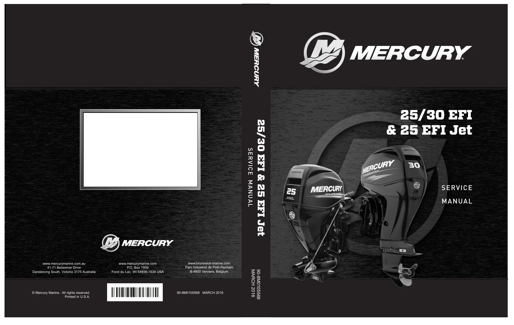
Mercury 25/30 EFI & 25 EFI Jet Outboard Service Manual 2016 – PDF Workshop Guide
Original price was: $52.95.$34.95Current price is: $34.95.
Complete 540-page Mercury 25/30 EFI & 25 EFI Jet outboard service manual (document 90-8M0105568, March 2016). Full ignition, fuel system, powerhead, mid-section, gear housing, tiller and remote control, recoil starter and jet drive coverage with specifications, diagnostics and step-by-step repair procedures. Instant PDF download.
Description
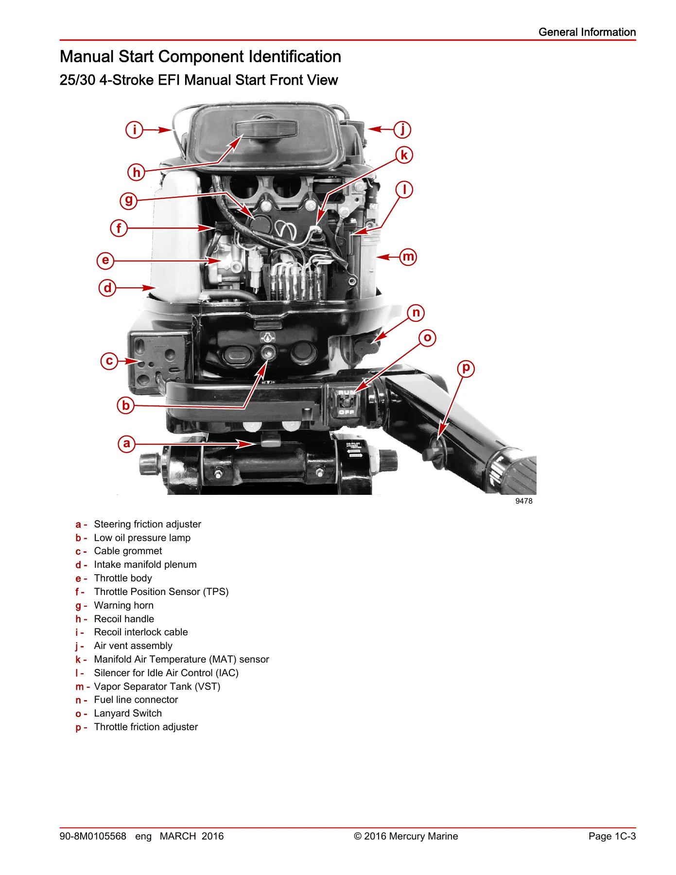
Published in March 2016 by the Mercury Marine Service Department under part number 90-8M0105568, this Mercury 25/30 EFI & 25 EFI Jet outboard service manual is the complete 540-page workshop reference for the three-cylinder four-stroke EFI outboards rated at 18.4 kW (25 hp) and 22.1 kW (30 hp), along with the 25 EFI Jet Drive variant. The manual was written and published by Mercury Marine to support the company’s own dealers’ mechanics and service personnel, and it is the same reference used for service-level work on these engines. Every system on these outboards is documented — ignition, charging and starting, fuel injection and diagnostics, powerhead and cylinder head, mid-section and clamp brackets, gear housing, throttle and shift linkage, tiller handle, recoil starter and the jet drive unit itself.
File Details
- Manual type: Service manual published by the Mercury Marine Service Department
- Brand: Mercury Marine
- Models covered: 25 EFI and 30 EFI three-cylinder four-stroke outboards plus the 25 EFI Jet Drive
- Language: English
- Page count: 540 pages
- File format: PDF
- Document number: 90-8M0105568
- Publication date: March 2016
Chapters Covered
- 1 – Important Information
- 2 – Electrical
- 3 – Fuel System
- 4 – Powerhead
- 5 – Mid-Section
- 6 – Lower Unit
- 7 – Attachments
- 8 – Manual Starter
- 9 – Jet Drive Outboard
Section 1 – Important Information
Opens with the 25/30 Master Specifications tables — model weights, transom heights, displacement, firing order, idle RPM, WOT RPM ranges, fuel system, ignition timing, charging and starting data, cylinder block and crankcase clearances, cooling system values, piston and oil system specifications and cylinder head data. Also includes prop charts for both the 25 hp and 30 hp three-cylinder EFI, the full maintenance schedule, fuel line and filter procedures, spark plug inspection, timing belt inspection, engine oil and filter changes, gearcase lubrication, corrosion anode service, propeller replacement, and the complete outboard installation chapter including drilling, steering bracket and control cable installation.
Section 2 – Electrical
Ignition theory and troubleshooting, the Computer Diagnostic System (CDS) workflow, warning horn and warning lamp logic, flywheel and stator removal, crank position sensor testing, ECM service, ignition coil testing, engine temperature coolant sensor, oil pressure switch, manifold air temperature sensor, manifold absolute pressure sensor, throttle position sensor, and the lanyard stop switch. Also covers the charging and starting system — voltage regulator/rectifier, wire harness removal and installation (remote and tiller), starter motor disassembly and reassembly, battery cable testing, plus the timing, synchronising and adjustment chapter with the timing belt procedure and the throttle linkage adjustments.
Section 3 – Fuel System
Fuel system theory of operation, air induction, vapor separator and fuel pressure regulator, fuel cooler, throttle body, all engine sensors and actuators. Includes the troubleshooting and diagnostics chapter, Guardian Protection System matrix, anti-siphon valve notes, fuel lift pump vacuum test, fuel pressure test, and the full service procedures chapter — fuel lift pump, high-pressure fuel filter, VST removal and reassembly, fuel cooler, throttle body, fuel rail, intake manifold and the Idle Air Control (IAC). The emissions chapter closes the fuel section with HC, CO and NOx standards and the certification label details.
Section 4 – Powerhead
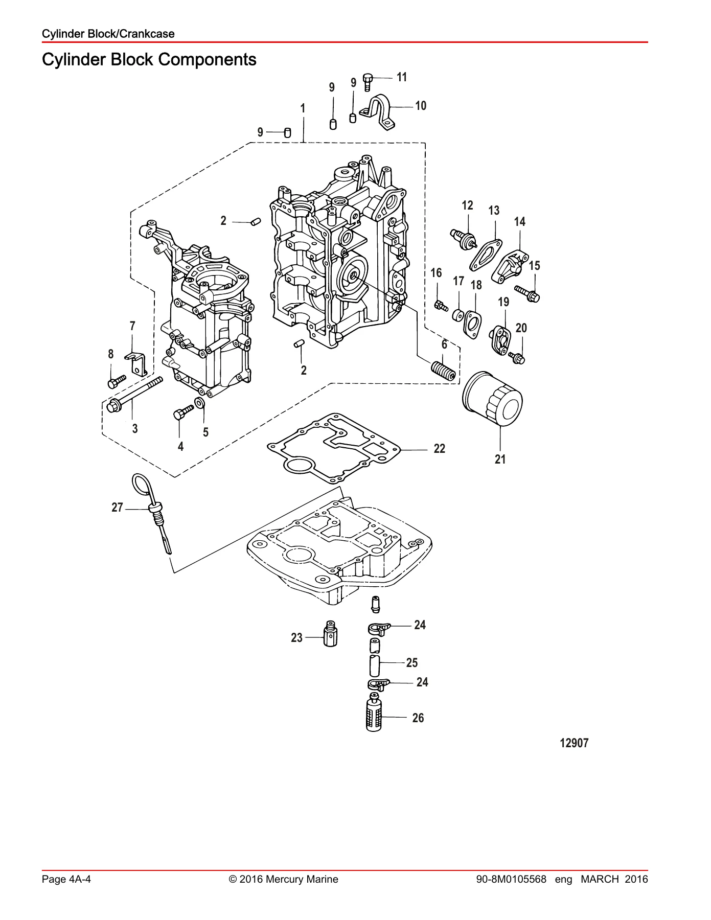
Cylinder block and crankcase specifications, piston specifications, powerhead removal, disassembly of the crankcase, measurement of cylinder bore, piston and piston ring clearances, connecting rod oil clearance, main bearing selection, crankshaft installation with Three Bond 1217F sealing, thermostat and anode service and full powerhead reassembly. The cylinder head chapter covers valve and valve guide inspection, valve seat reconditioning, camshaft and rocker arm installation, cylinder head installation and the complete valve adjustment procedure across all three cylinders. The oil pump and cooling system chapters round out the powerhead section.
Section 5 – Mid-Section
Driveshaft housing, swivel bracket and clamp bracket components for both power trim/gas assist models and manual tilt models, plus exhaust covers and lower motor mount replacement. The Power Trim chapter documents specifications, hydraulic diagram, trim and tilt circuits, trail-over system, electrical troubleshooting with relay tests, trim motor and pump service, and the trim cylinder disassembly and reassembly with torque values for the jam nut and trim cylinder. The Gas Assist Manual Trim/Tilt chapter handles removal, bushing replacement and installation.
Section 6 – Lower Unit
The full gear housing chapter — draining and inspecting gear lubricant, gear housing removal, bearing carrier disassembly, propeller shaft disassembly, water pump and driveshaft disassembly, pinion and forward gear inspection, and complete reassembly with pinion bearing installation, forward gear bearing installation, bearing carrier reassembly, water pump base reassembly, propeller shaft reassembly, pinion gear height adjustment, forward gear backlash adjustment with the shim chart, shift shaft installation and gear housing installation with coupler adjustment.
Sections 7, 8 and 9 – Attachments, Manual Starter and Jet Drive
Section 7 covers the throttle and shift linkage components, shift and cam rod components, the throttle only operation, neutral safety start switch, remote control shift control removal and installation, and the complete tiller handle chapter — power trim switch, throttle cable and linkage adjustments, tiller handle disassembly and assembly. Section 8 covers the recoil starter — removal, disassembly, spring and rope service, assembly and the neutral interlock cable adjustment. Section 9 covers the Jet Drive Outboard — jet unit and water pump components, shift linkage for both tiller and remote models, water testing for cavitation, jet drive disassembly, bearing carrier and liner service, jet drive installation, shift lever and shift link rod procedures, shift cam adjustment and the neutral interlock cable.
Specification and Diagnostic Coverage
The Master Specifications section at the front of the manual brings every critical number into one place — 526 cc displacement, 61.0 mm standard bore, idle at 850 ± 25 RPM, WOT at 5000–6000 RPM for the 25 hp, 5250–6250 RPM for the 30 hp and 5000–5500 RPM for the 25 Jet. Ignition timing is fixed at 5° ± 5° BTDC at idle and 38° BTDC at WOT, with the ECM RPM limiter (Guardian) kicking in at 2800 RPM during a fault and overspeed protection at 6300 RPM. Crankshaft position sensor resistance is 148–222 ohms, ignition coil primary 0.17–0.23 ohms, secondary 3.3–4.9 k ohms, spark plug lead 7.1–11.1 k ohms. Fuel pressure from the electric pump runs at 294 kPa ± 10% (42.6 psi ± 10%). The CDS (Computer Diagnostic System) chapter documents the full data stream, fault status lists, and the special service mode behaviour so you can read live sensor values and historic faults rather than guessing.
What This Mercury 25/30 EFI Service Manual Enables You to Do
Every procedure in this Mercury outboard workshop manual is written for the technician working on these specific three-cylinder four-stroke EFI engines, not a generic outboard. That means the torque figures — flywheel nut at 150 Nm, cylinder head bolts staged at 10 Nm then 30 Nm, gearcase retaining screws at 19 Nm — the clearances, the shim charts and the diagnostic fault-code tables all match the 25/30 EFI and 25 Jet hardware exactly. Whether you are diagnosing a no-start condition on the CDS, chasing a low-oil-pressure warning, rebuilding a powerhead after submersion, setting the pinion height on a gearcase, or performing the annual service on a 25 EFI Jet, this is the reference the job was designed against.
IMAGES PREVIEW
Instant PDF Delivery
Your download is available immediately after checkout. No shipping, no waiting for a parcel — just a single indexed PDF you can open on a laptop in the workshop, a tablet on the bench, or a phone next to the outboard, and print the pages you need for the job in front of you. Keep it on file for the life of the engine.


Reviews
There are no reviews yet.