
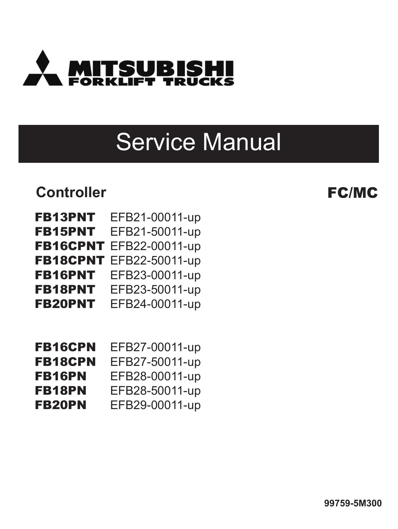
Mitsubishi FB13-20PN PNT Controller Service Manual – FC/MC Electric Forklift Repair Guide 99759-5M300
Original price was: $39.95.$24.95Current price is: $24.95.
Complete Mitsubishi controller service manual for FB13PNT through FB20PNT and FB16CPN through FB20PN electric forklift trucks. Covers FC and MC control systems, inverters, EPS, CAN diagnostics, error codes, motors and setup options. Document 99759-5M300.
Description
Mitsubishi FB13-20PN PNT Controller Service Manual – FC/MC Electric Forklift Repair Guide
This is the full Mitsubishi Forklift Trucks controller service manual, document number 99759-5M300, covering the FC (Fingertip Control) and MC (Manual Control) electric forklift families from the FB13PNT series through the FB20PN series. It is the workshop-level guide technicians use to diagnose, service and rebuild the complete controller system on these AC-powered trucks — from the logic unit and CAN network down to the individual traction, pump and EPS motors. Every procedure, illustration and specification inside this Mitsubishi FB13-20PN PNT controller service manual reflects the serial numbers in effect at the time of publication.
File Details
- Manual type: Controller Service Manual
- Brand: Mitsubishi Forklift Trucks (MCFA)
- Document number: 99759-5M300
- Publication date: 09/11 (September 2011)
- Language: English
- File format: PDF
- Page count: 292 pages
- Coverage: FB13PNT, FB15PNT, FB16CPNT, FB18CPNT, FB16PNT, FB18PNT, FB20PNT, FB16CPN, FB18CPN, FB16PN, FB18PN, FB20PN
Chapters Covered
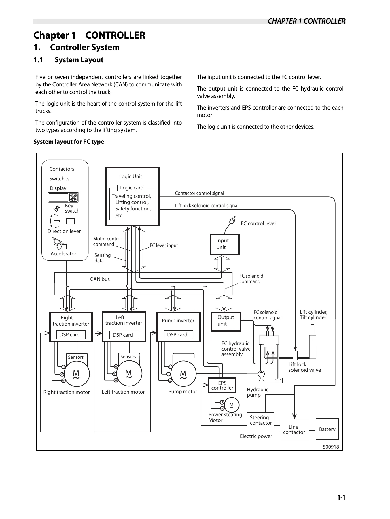
- Chapter 1 — Controller: System Layout; Controller Area Network (CAN); Outline of Logic Unit; Outline of Inverter; Outline of EPS Controller; Outline of Input Unit; Outline of Output Unit
- Traction Controller Features: Modification of Traction Characteristics; Unit-rollback; Boost; Limitation of Maximum Travel Speed; Turning Speed Limit Function; Pitching Control (option)
- Lifting Controller Features: Setting and Limitation of Lift Work Speed; Lift Stop; Load Meter (option); Tilt Horizon (option)
- Other Features: PDS (Presence Detection System); Display Function; Parking Brake Interlock; BDI Display; Hour Meter
- Setup Options: Group-1 Basic Functions (#1–#10); Group-2 Detailed Functions (#11–#39); Group-3 Model Information (#40–#55)
- Diagnostics: Self-Diagnostics; Power Steering Diagnostics; Run Time Diagnostics; Fail-Safe Restriction List
- Removal and Installation: Inverter Discharging Procedure; Replacing Inverter; Replacing DSP Card; Replacing Logic Unit; Replacing EPS Controller; Replacing Logic Card; Replacing Power Supply Card; Replacing Input/Output Unit (FC model)
- Basic Check: Testing Tools; Measurement of Card Voltage; Checking Contactor Coil; Checking Contactor Tips; Checking Inverter; Regeneration Check
- AC Motor System Basics: Feature of AC Motor; Speed Control of Induction Motors; Inverter Operation
- Chapter 2 — Troubleshooting for Control Circuits: Before Replacing Devices; Service Tool Connection; Cleaning Harness Connectors; List of Error Codes; Individual troubleshooting charts for every fault code (E0, E1, E2, E5, E6, E7, E9, 14, 15, 16, 24, 25, 26, 34, 35, 40, 41, 45, 46, 47, 49, 50, 51, 52, 53, 54, 55, 56, E, (E), H1–H4, (L), EE, 60–62, 63–65, 67–68, 71–76, 78–82, A4, A5, A7, A8, and non-coded warnings)
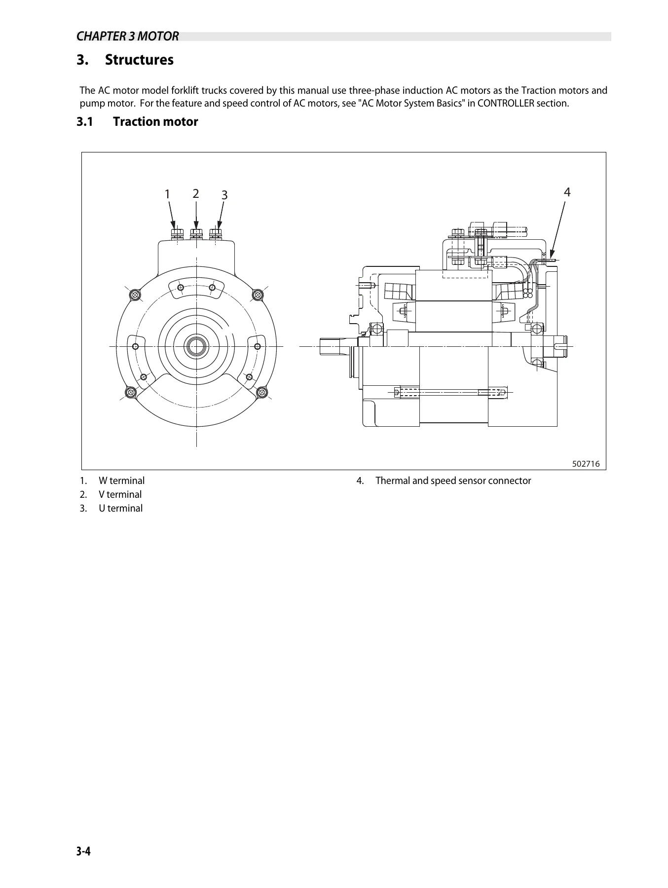
- Chapter 3 — Motor: Motor Installation Positions (3W/4W); Specifications; Structures of Traction, Pump and EPS motors; Removing and Disassembling Traction Motor; Inspecting Rotor, Motor and Insulation; Reassembling Traction Motor; Removing and Disassembling Pump Motor; Inspecting and Reassembling Pump Motor; Tightening of High-Power Cable Terminals; Removing, Disassembling and Inspecting EPS Motor (armature, brushes, oil seal, permanent magnet)
- Chapter 4 — How to Read Circuit Diagrams: Schematic Diagrams; Connector Diagrams; Symbols; Sheet Symbols; Connecting Lines; Equipment Numbering; Relay Contactors and Coils; GND Indication; Alternate Specifications
- Chapter 5 — Circuit Diagram: Full electrical circuit diagrams for the control system
Across the roughly 290+ pages of this Mitsubishi FB13-20PN PNT controller service manual, the coverage runs far past a simple overview. The first chapter establishes how the five-to-seven independent controllers communicate over CANbus 2.0B at 500 kbps and how the logic unit orchestrates motor control commands, hydraulic output and safety monitoring. From there the manual moves into the traction and lifting controller features — acceleration curves, regeneration modes, unti-rollback behavior on grades, boost override, turning speed limits, load meter and tilt horizon options — then breaks the entire setup system down into three option groups with full value tables so a technician can reconfigure a truck to match its real hydraulic control type, battery type, mast type and valve section count. The diagnostics chapter and its companion Chapter 2 error-code coverage are the operational heart of the book: for each fault number there is a defined trigger, a description of the truck behavior it produces, and a step-by-step check procedure walking through connectors, voltages, resistance values and replacement decisions.
What This Mitsubishi Electric Forklift Controller Repair Guide Delivers
This is the Mitsubishi FB13-20PN PNT controller service manual you reach for when a truck stops answering the pedal, when the display throws a code you have never seen, or when a traction inverter has to come out and go back in without cooking the DSP card. The document is written around the actual repair workflow: identify the fault code, walk the diagnostic tree, verify each connector and voltage reading, and only then decide whether a card, a contactor, a motor or a wiring run needs to be replaced.
- Fault-code driven diagnosis — every stored error code (overheating, over-current, sensor faults, contactor faults, battery voltage faults, EPS and steering faults, communication faults) has its own troubleshooting chart with the exact measurement points, expected values and fallback decisions.
- Controller and card replacement — detailed removal and installation procedures for the inverter, DSP card, logic unit, EPS controller, logic card, power supply card, input unit and output unit, including the mandatory inverter discharging procedure before any electrical work.
- Setup Option reconfiguration — complete tables for Group 1, Group 2 and Group 3 setup options so the truck’s model information, battery voltage, hydraulic control type, mast type and speed/power limits can be restored or adjusted correctly.
- Motor service — disassembly, inspection and reassembly sequences for the three-phase AC traction motors, the pump motor and the DC EPS motor, with insulation testing procedures, bearing and seal guidance, brush wear limits and commutator tolerances.
- Circuit and connector interpretation — a full guide to reading the schematic and connector diagrams, plus the complete circuit diagram set in Chapter 5.
Why It Matters for FB13PNT – FB20PN Service Work
Electric forklift controllers do not forgive guesswork. A traction inverter that is not discharged properly before removal can be destroyed on contact. A DSP card that is seated unevenly, or a flat cable pinched under the cover, produces faults that look like motor failures. A wrongly configured Setup Option Group 3 makes a truck run in the wrong hydraulic mode or refuse to move at all. That is why working from the correct Mitsubishi FB13-20PN PNT controller service manual — not a generic forklift book and not a guess — saves both time and hardware. This guide gives the technician the actual trigger conditions, thresholds and test values Mitsubishi specifies, so diagnosis follows evidence instead of trial replacement.
IMAGES PREVIEW
Instant PDF Delivery
This Mitsubishi FB13-20PN PNT controller service manual is delivered as an instant-download PDF. There is no shipping, no waiting, and no physical book to keep track of in the workshop. Print the pages you need for the job at hand, keep the full file on a laptop or tablet in the service bay, and search or jump to any chapter, fault code or connector reference when a truck is on the lift. Whether you are a fleet technician, an independent forklift mechanic, or an owner maintaining your own FB-series electric truck, having the correct 99759-5M300 repair guide on hand is the difference between a repair that holds and a comeback that does not.
Reviews
There are no reviews yet.