★ TRUSTED BY 321,897+ PROFESSIONALS WORLDWIDE
🏒
Trusted Business
Verified & Licensed
πŸ›‘οΈ
Virus Free Files
100% Safe Downloads
πŸ”’
Secure Payment
SSL Protected
⚑
Instant Delivery
Available Immediately
Sale!

Mitsubishi Forklift Chassis & Mast Service Manual – GP40N1 GP45N1 GP50N1 GP55N1 DP40NM1 DP55NM1

Original price was: $39.95.Current price is: $24.95.

Complete chassis and mast service manual for Mitsubishi/CAT lift trucks GP40N1 through GP55N1 and DP40NM1 through DP55NM1. Covers rear axle, brakes, steering, hydraulics, masts and forks with full specifications, torque values and troubleshooting.

⚑
Instant PDF Download
Available immediately
πŸ’Ύ
Save to Your Device
Download & keep forever
πŸ›‘οΈ
Antivirus Scanned
100% virus-free
🌍
Trusted Worldwide
175,000+ customers

Description

Mitsubishi Forklift Chassis & Mast Service Manual – GP and DP Series

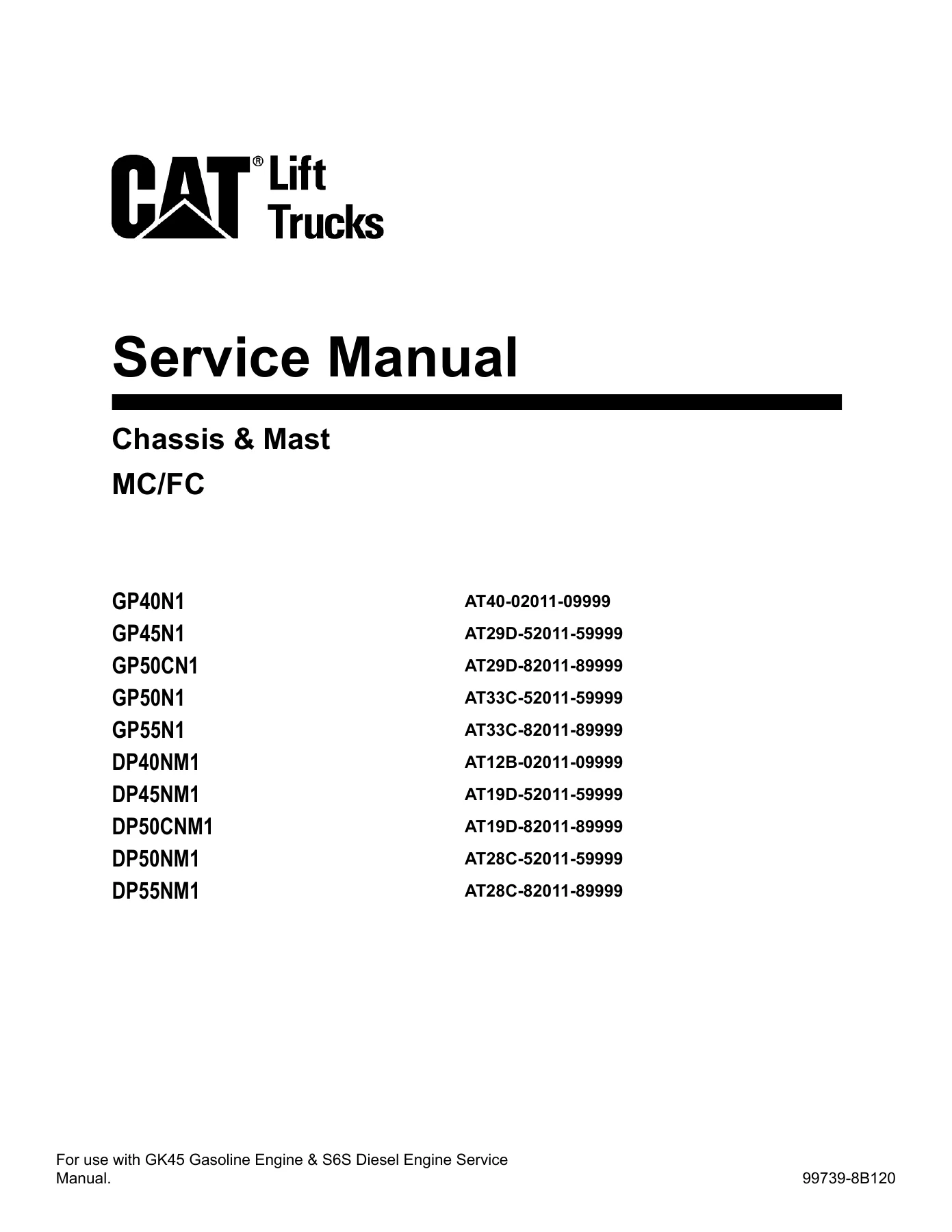
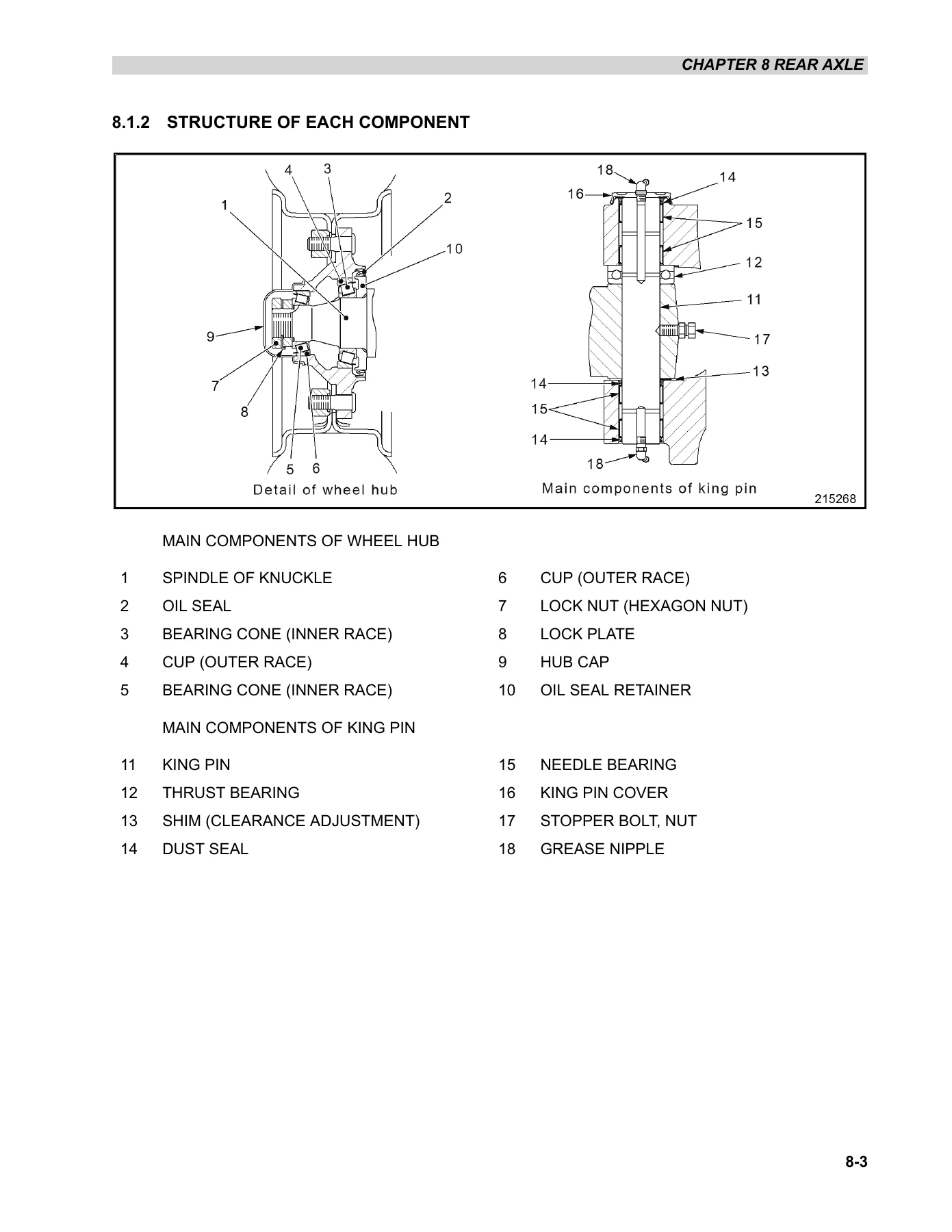
This is the complete chassis and mast service manual for Mitsubishi and CAT lift truck models GP40N1, GP45N1, GP50CN1, GP50N1, GP55N1, DP40NM1, DP45NM1, DP50CNM1, DP50NM1 and DP55NM1. Document number 99739-8B120. It covers the chassis and mast systems in full workshop detail: rear axle assembly, wheel hubs, king pins, steering cylinders, tie rods, dry and wet brake systems, parking brake valves, steering valve, hydraulic pump, MC and FC control valves, lift and tilt cylinders, and simplex, duplex and triplex masts with forks. Every procedure is written for the technician working on the machine, with removal and installation sequences, disassembly and reassembly steps, inspection limits and adjustment values.

File Details

  • Manual type: Chassis & Mast Service Manual
  • Brand: Mitsubishi / CAT Lift Trucks (Mitsubishi Logisnext Americas)
  • Document number: 99739-8B120
  • Models covered: GP40N1, GP45N1, GP50CN1, GP50N1, GP55N1, DP40NM1, DP45NM1, DP50CNM1, DP50NM1, DP55NM1
  • Language: English
  • Page count: 322 pages
  • File format: PDF

Chapters Covered

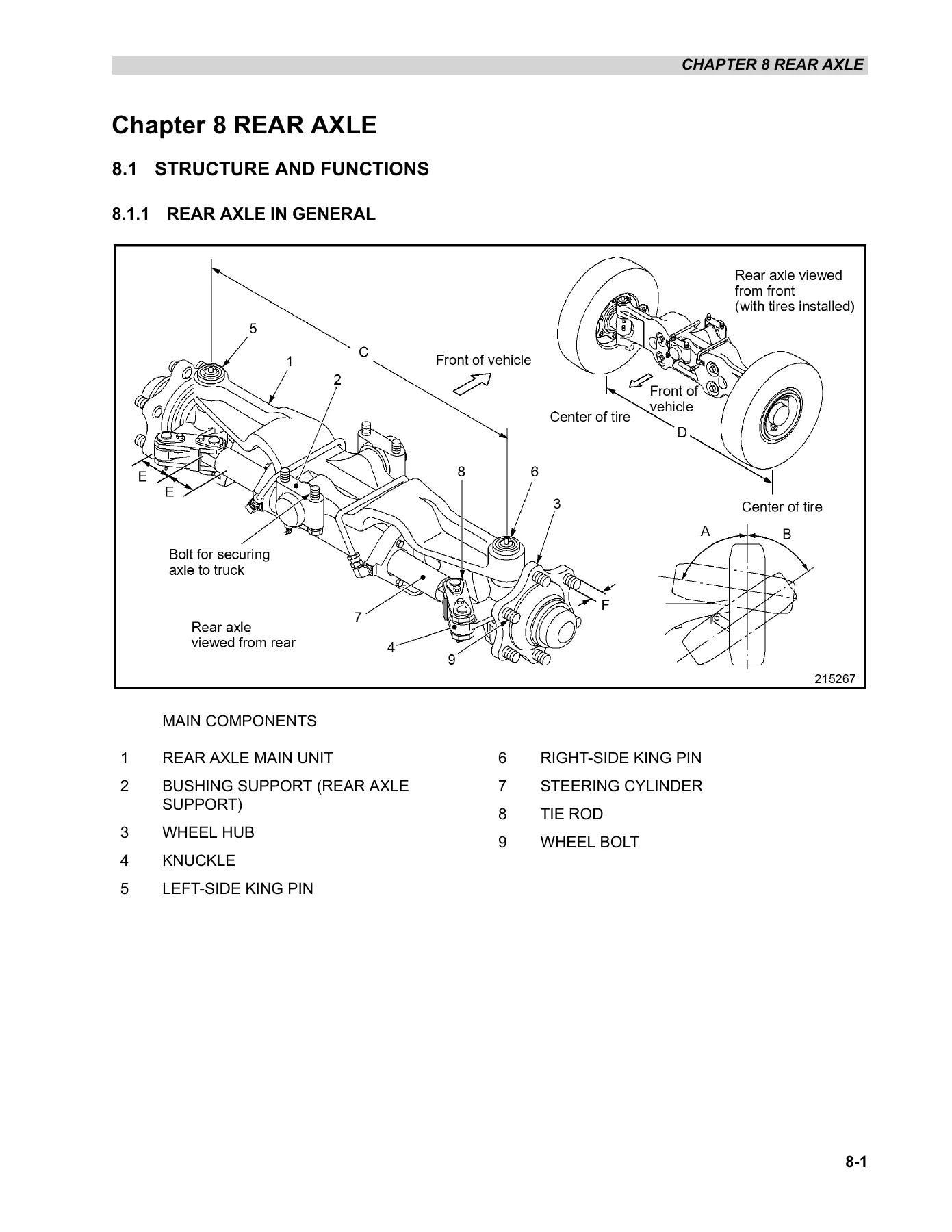
  • Chapter 8 – Rear Axle: structure and functions, rear axle in general, wheel hub components, king pin components, tie rod, steering cylinder; removal and installation of rear wheels and rear axle assembly; disassembly and reassembly of wheel hub, knuckle (king pin) and steering cylinder; troubleshooting; service data
  • Chapter 9 – Brake System: dry type brake system, wet type brake system, wheel brakes for 4.0/4.5 ton and 5.0C/5.0/5.5 ton classes, parking brake valve, wet disc brake assembly, auto deceleration valve, wheel cylinder, inspection and adjustment, brake line bleeding, braking performance test, oil pressure measurement, parking brake emergency release, troubleshooting, service data
  • Chapter 10 – Steering System: steering system structure and functions, steering valve, steering column, disassembly and reassembly of valves, hoses and pipes, steering wheel and steering valve, tilt lock lever, STC (Snap-To-Connect) connectors, troubleshooting, service data
  • Chapter 11 – Hydraulic System: hydraulic circuit diagrams for MC and FC control valves, hydraulic tank, gear pump, MC control valve operation, FC control valve operation, flow regulator valve, down safety valve, simplex and duplex lift cylinders, first cylinder of duplex and triplex mast, tilt cylinder, disassembly and reassembly of hydraulic pump, lift cylinder, tilt cylinder, flow regulator valve, piping, suction strainer and return filter, inspection and adjustment, troubleshooting, service data
  • Chapter 12 – Mast and Forks: simplex mast (dual panoramic 5V40C to 5V50C), duplex mast (dual full-free panoramic 5F40C to 5F50C), triplex mast (triple full-free panoramic 5M40C to 5M50C), mast operation, removal and installation, disassembly and reassembly, mast roller and strip replacement without removing the mast, inspection and adjustment, chain tension, chain elongation, fork service, troubleshooting, service data
  • Chapter 13 – Service Data: maintenance schedule, tightening torque for standard bolts and nuts (metric fine and coarse thread), periodic inspection parts, lubrication instructions, fuel and lubricant specifications, adjustment values and oil quantities, LPG fuel quality, special service tools

Complete PDF Bookmark Tree

Complete Bookmarks

The complete bookmarks in the β€œMitsubishi Forklift Chassis & Mast Service Manual – GP40N1 GP45N1 GP50N1 GP55N1 DP40NM1 DP55NM1” are as follows:

FOREWORD
HOW TO USE THIS MANUAL
SAFETY
CHANGE LOG
CHAPTER 1 GENERAL INFORMATION
1.1 Model View
1.1.1 Model View
1.2 Lift Truck Models Covered
1.2.1 LiftTruck Models Covered
1.3 Serial Number Locations
1.3.1 Serial Number Locations
1.4 Dimensions
1.4.1 Dimensions
1.5 Technical Data
1.5.1 Technical Data
1.5.2 Performance
1.6 Performance
1.6.1 Performance
CHAPTER 2 COOLING SYSTEM
2.1 Specifications
2.1.1 Specifications
2.2 Structure
2.2.1 Structure
2.3 Removal and Installation
2.3.1 Fan Belt Removal
2.4 Inspection and Adjustment
2.4.1 Fan Belt
2.4.2 Radiator
2.4.3 Upper Hose, Lower Hose
2.4.4 Coolant
2.5 Troubleshooting
2.5.1 Troubleshooting
CHAPTER 3 ELECTRIC SYSTEM
3.1 Chassis Electrical Devices Wiring Outline
3.1.1 Gasoline Model
3.1.2 Diesel Model
3.1.3 Gasoline and Diesel Models
3.1.4 Power Relay Supersession
3.2 Structure
3.2.1 Console Box
3.2.2 Main Electrical Components
3.2.3 Table of Lamps
3.3 Console Box
3.3.1 Disassembly
3.4 Battery Maintenance
3.4.1 State of Charge and Electrolyte Specific Gravity (S.G.) Adjustment
3.4.2 Specific Gravity Reading and State of Charge
3.4.3 Charging Precautions
3.5 Instrument Panel
3.5.1 Instrument Panel Screen Components
3.5.2 Basic Screen Display
3.5.3 Basic Operation
3.5.4 When an Error Occurs
3.5.5 Warning Lamps
3.5.6 Optional Functions
3.5.7 Hour Meters
3.5.8 Troubleshooting
3.6 Wire Color
3.6.1 Wire Color
3.6.2 List of Wire Colors
3.7 Troubleshooting
3.7.1 Starter System
3.7.2 Gauges
3.7.3 Lighting System
3.7.4 Short Horn Service Life
3.7.5 Horn Contact Ring Failures
CHAPTER 4 CONTROLLERS
4.1 Outline
4.1.1 Outline
4.2 Main Functions of Controllers
4.2.1 Main Functions of Controllers
4.2.2 Instrument Panel
4.2.3 VCM (Vehicle Control Module) 4
4.2.4 ECM (Gasoline Engine Control Module)
4.2.5 DCM (Diesel Engine Control Module)
4.2.6 Remote Input/Output Units
4.2.7 OCM (Optional Control Module)
4.2.8 GSE Connector
4.3 Service Tool Functions
4.3.1 Service Tool Menus
4.3.2 Service Tool Box
4.4 Mast Interlock System
4.4.1 Function
4.4.2 Mast Interlock System of VCM-4 Controller, Checking Procedure
4.4.3 Active Test Inspection Procedure
4.5 Driving Interlock System
4.5.1 Function
4.5.2 Driving Interlock System, Checking Procedure
4.5.3 Active Test Inspection Procedure
4.6 Seat Belt Warning Lamp
4.6.1 Function
4.6.2 Seat Belt Warning Lamp Checking Procedure
4.7 Parking Brake Warning Buzzer and Lamp
4.7.1 Function
4.7.2 Parking Brake Warning Buzzer/Lamp Checking Procedure
4.7.3 Parking Brake Warning Buzzer/Lamp Checking Procedure with Key in OFF Position
4.8 Harness Code List
4.8.1 Harness Code List
4.9 Controller Output Details
4.9.1 VCM-4 Controller
4.9.2 Seat Switch/Seat Belt Switch
4.9.3 Parking Brake Switch
4.9.4 Direction Lever
4.9.5 Speed Sensor
4.9.6 T/M Solenoid
4.9.7 Unload Solenoid
4.9.8 Lift Lock Solenoid
4.9.9 Warning Buzzer
4.9.10 Warning Buzzer Relay
4.9.11 Warning Buzzer Circuit
4.9.12 Instrument Panel
4.9.13 OCM
4.9.14 Service Brake Solenoid
4.9.15 Parking Brake Solenoid
4.10 Error Codes and Troubleshooting
4.10.1 Error Code Display
4.10.2 Diagnosis Table (F Code)
4.10.3 Error Codes and Troubleshooting
4.11 Locations of Sensors and Switches
4.11.1 Locations of Sensors and Switches
CHAPTER 5 POWER TRAIN
5.1 Removal and Installation (MC Models)
5.1.1 Removal and Installation of Engine and Transmission Assembly (LPG Models)
5.1.2 Removal and Installation of Engine and Transmission Assembly (Diesel Models)
5.2 Removal and Installation (FC Models)
5.2.1 Removal of Engine and Transmission Assembly
5.2.2 Suggestions for Replacing Wet Disc Brake Oil and Filter
5.3 Removal and Installation (Wet disc brake)
5.3.1 Removal of Engine and Transmission Assembly
5.4 Service Data
5.4.1 Service Data
CHAPTER 6 POWERSHIFT TRANSMISSION
6.1 Structure
6.1.1 Transmission
6.1.2 Power Transmission Path
6.1.3 Torque Converter
6.1.4 Powershift Transmission Control
6.1.5 Control Valve
6.1.6 Main Regulator Valve
6.1.7 Parking Brake Activation
6.1.8 Releasing parking brake with the release bolt
6.1.9 Schematic Diagram of Powershift Transmission Hydraulic System
6.1.10 Powershift Transmission External View
6.2 Removal and Installation
6.2.1 Removal
6.2.2 Installation
6.3 Transmission Exterior Parts
6.3.1 Disassembly
6.3.2 Reassembly
6.4 Torque Converter
6.4.1 Disassembly
6.4.2 Inspection and Repair
6.4.3 Reassembly
6.5 Transmission
6.5.1 Disassembly
6.5.2 Inspection and Repair
6.5.3 Reassembly
6.6 F2 Clutch Pack Assembly
6.6.1 Disassembly
6.6.2 Inspection and Repair
6.6.3 Reassembly
6.7 F1 Clutch Pack Assembly
6.7.1 Disassembly
6.7.2 Inspection and Repair
6.7.3 Reassembly
6.8 R1 Clutch Pack Assembly
6.8.1 Disassembly
6.8.2 Inspection and Repair
6.8.3 Reassembly
6.9 Parking Brake Assembly
6.9.1 Disassembly
6.9.2 Inspection and Repair
6.9.3 Reassembly
6.10 Gear Pump Assembly
6.10.1 Disassembly
6.10.2 Inspection and Repair
6.10.3 Reassembly
6.11 Control Valve
6.11.1 Disassembly
6.11.2 Inspection and Repair
6.11.3 Reassembly
6.12 Main Regulator Valve
6.12.1 Disassembly
6.12.2 Inspection and Repair
6.12.3 Reassembly
6.13 Inspection and Adjustment
6.13.1 Oil Pressure Measurement
6.13.2 Brake Inching Pedal Adjustment
6.13.3 Inching Cable, Adjustment
6.14 Troubleshooting
6.14.1 Troubleshooting
6.14.2 DTC F-85, F-87, F-93
6.14.3 Diagnostic Trouble Code DTC-F88
6.15 Service Data
6.15.1 Service Data
CHAPTER 7 FRONT AXLE AND REDUCTION DIFFERENTIAL
7.1 Specifications
7.1.1 Specifications
7.2 Structure
7.2.1 Standard Model (with Drum Brake)
7.2.2 Option Model (with Wet Disc Brake)
7.3 Removal and Installation
7.3.1 Front Wheels (Common to Standard and Option Truck)
7.3.2 Shoe and Lining (Standard Truck)
7.3.3 Wet Disc Brake Assembly (Option Truck)
7.3.4 Front Axle Assembly (Standard Truck)
7.3.5 Front Axle Assembly (Option Truck)
7.3.6 Removal and Installation of Each Assembly (Standard Truck)
7.3.7 Removal and Installation of Each Assembly (Option Truck)
7.4 Disassembly and Reassembly
7.4.1 Tube Assembly and Final Reduction (Standard Truck)
7.4.2 Tube Assembly and Final Reduction (Option Truck)
7.4.3 Wear Gauge for Wet Disc Brakes
7.4.4 Reduction Differential (Common to Standard and Option Truck)
7.4.5 Troubleshooting (Common to Standard and Option Truck)
7.4.6 Service Data
CHAPTER 8 REAR AXLEp. 3
8.1 Structure and Functionsp. 3
8.1.1 Rear Axle in Generalp. 3
8.1.2 Structure of Each Componentp. 4
8.1.3 Steering Cylinderp. 6
8.2 Removal and Installationp. 8
8.2.1 Rear Wheel and Rear Axle Assemblyp. 8
8.3 Disassembly and Reassemblyp. 11
8.3.1 Disassembly and Reassembly of Wheel Hubp. 11
8.3.2 Disassembly and Reassembly of Knuckle (King Pin)p. 13
8.3.3 Disassembly and Reassembly of Steering Cylinderp. 15
8.3.4 Disassembly and Reassembly of Tie Rodp. 17
8.4 Troubleshootingp. 18
8.4.1 Troubleshootingp. 18
8.5 Service Datap. 18
8.5.1 Service Datap. 18
CHAPTER 9 BRAKE SYSTEMp. 21
9.1 Structurep. 21
9.1.1 Brake System (Dry type brake)p. 21
9.1.2 Wheel Brakes (Dry type brake)p. 25
9.1.3 Parking Brake Valve (Dry type brake)p. 27
9.1.4 Brake System (Wet type brake)p. 27
9.1.5 Wet Disc Brake Assemblyp. 30
9.1.6 Parking Brake Valve (Wet type brake)p. 32
9.1.7 Auto Deceleration Valve (Wet type brake)p. 32
9.2 Disassembly and Reassemblyp. 33
9.2.1 Wheel Brakes (Dry type brake)p. 33
9.2.2 Wheel Cylinder (Dry type brake)p. 43
9.2.3 Parking Brake Valve (Dry type brake)p. 46
9.2.4 Wet Disc Brake Assemblyp. 47
9.2.5 Parking Brake Valve (Wet type brake)p. 50
9.3 Inspection and Adjustmentp. 52
9.3.1 Automatic Adjuster Test (Dry type brake)p. 52
9.3.2 Manual Adjustment (Dry type brake)p. 52
9.3.3 Brake Pedal Adjustment (Common to dry and wet type)p. 53
9.3.4 Brake Lines Bleeding (Dry type brake)p. 53
9.3.5 Braking Performance Test (Dry type brake)p. 54
9.3.6 Procedure for Flushing and Air Bleeding after Assembly (Wet type brake)p. 54
9.3.7 Braking performance test (Wet type brake)p. 55
9.3.8 Oil Pressure Measurement (Dry type brake)p. 55
9.3.9 Oil Pressure Measurement (Wet type brake)p. 56
9.3.10 Parking Brake Emergency Release (Common to dry and wet type)p. 56
9.4 Troubleshootingp. 59
9.4.1 Troubleshootingp. 59
9.4.2 Brake Light Staying Onp. 61
9.5 Service Datap. 63
9.5.1 Service Datap. 63
CHAPTER 10 STEERING SYSTEMp. 67
10.1 Structure and Functionsp. 67
10.1.1 Steering Systemp. 67
10.1.2 Steering Valvep. 68
10.1.3 Steering Columnp. 69
10.2 Disassembly and Reassemblyp. 71
10.2.1 Valves, Hoses and Pipes, Disassembly and Reassemblyp. 71
10.2.2 Removal and Installation of Steering Wheel and Steering Valvep. 72
10.2.3 Steering Wheelp. 72
10.2.4 Steering Valvep. 74
10.2.5 Tilt Lock Leverp. 74
10.3 Steering Valvep. 75
10.3.1 Disassembly Procedurep. 75
10.3.2 Reassembly Sequencep. 78
10.4 Troubleshootingp. 82
10.4.1 Troubleshootingp. 82
10.5 Service Datap. 83
10.5.1 Service Datap. 83
10.6 STC (Snap-to-Connect)p. 84
10.6.1 Installing and Removing STC Connectorp. 84
10.6.2 Connection and Latching Checkp. 85
10.6.3 STC Componentsp. 85
CHAPTER 11 HYDRAULIC SYSTEMp. 89
11.1 Structure and Functionsp. 90
11.1.1 Outlinep. 90
11.1.2 Hydraulic Circuit Diagram (for models with MC control valve)p. 91
11.1.3 Hydraulic Circuit Diagram (for models with FC control valve)p. 93
11.1.4 Hydraulic Tankp. 95
11.1.5 Hydraulic Pump (Gear Pump)p. 97
11.1.6 Control Valvep. 97
11.1.7 Flow Regulator Valve (models with FC control valve only)p. 100
11.1.8 Down Safety Valvep. 100
11.1.9 Lift Cylinderp. 101
11.1.10 Tilt Cylinderp. 104
11.2 Disassembly and Reassemblyp. 106
11.2.1 Hydraulic Pumpp. 106
11.2.2 Lift Cylinderp. 108
11.2.3 Tilt Cylinderp. 120
11.2.4 Flow Regulator Valvep. 124
11.2.5 Pipingp. 125
11.2.6 Suction Strainer and Return Filterp. 126
11.3 Inspection and Adjustmentp. 127
11.3.1 Hydraulic Tankp. 127
11.3.2 Control Valvep. 129
11.3.3 Natural Descent Testp. 130
11.3.4 Natural Forward Tilt Testp. 131
11.4 Troubleshootingp. 131
11.4.1 Troubleshootingp. 131
11.5 Service Datap. 135
11.5.1 Service Datap. 135
11.6 MC Control Valvep. 139
11.6.1 Outlinep. 139
11.6.2 Names of Partsp. 141
11.6.3 Control Valve Operationp. 143
11.6.4 Pressure Control (Relief) Valve Operationp. 149
11.6.5 Flow Regulating Valve (FRV)p. 151
11.6.6 Cautions for usep. 152
11.7 FC Control Valvep. 153
11.7.1 Structure and Functionsp. 153
11.7.2 Procedures and Suggestions for Removal and Installationp. 173
11.7.3 Disassembly and Reassemblyp. 174
11.8 Hydraulic Oil Tank Breatherp. 198
11.8.1 Hydraulic Oil Tank Breatherp. 198
CHAPTER 12 MAST AND FORKSp. 201
12.1 Simplex Mastp. 201
12.1.1 Mast Systemp. 201
12.2 Structure and Functionsp. 202
12.2.1 Simplex Mast (Dual Panoramic 5V40C to 5V50C)p. 202
12.2.2 Mast Operationp. 203
12.3 Removal and Installationp. 203
12.3.1 Mast and Lift Bracket Assemblyp. 203
12.4 Disassembly and Reassemblyp. 206
12.4.1 Simplex Mast Disassemblyp. 206
12.4.2 Simplex Mast Reassemblyp. 209
12.5 Removal and Installation of Mast Rollers and Strips without Removingp. 216
12.5.1 Simplex Mastp. 216
12.6 Inspection and Adjustment (Simplex Mast)p. 217
12.6.1 Inspection and Adjustment (Simplex Mast)p. 217
12.6.2 Forksp. 217
12.6.3 Chain Tension Inspection and Adjustmentp. 218
12.6.4 Chain Elongation Measurementp. 219
12.6.5 Clearance Adjustment between Lift Bracket Roller and Inner Mastp. 219
12.6.6 Mast Roller Clearance Adjustmentp. 221
12.6.7 Mast Strip Clearance Inspection and Adjustmentp. 222
12.6.8 Mast Tilt Angle Adjustmentp. 222
12.6.9 Right and Left Lift Cylinder Stroke Inspection and Adjustmentp. 223
12.7 Troubleshooting (Simplex Mast)p. 224
12.7.1 Troubleshooting (Simplex Mast)p. 224
12.8 Service Data (Simplex Mast)p. 225
12.8.1 Service Data (Simplex Mast)p. 225
12.9 Duplex Mastp. 228
12.9.1 Mast Systemp. 228
12.10 Structure and Functionsp. 228
12.10.1 Duplex Mast (Dual Full-Free Panoramic 5F40C to 5F50C)p. 228
12.10.2 Mast Operationp. 230
12.11 Removal and Installationp. 230
12.11.1 Mast and Lift Bracket Assemblyp. 230
12.12 Disassembly and Reassemblyp. 233
12.12.1 Duplex Mast Disassemblyp. 233
12.12.2 Duplex Mast Reassemblyp. 236
12.13 Removal and Installation of Mast Rollers and Strips without Removingp. 244
12.13.1 Duplex Mastp. 244
12.14 Inspection and Adjustment (Duplex Mast)p. 245
12.14.1 Inspection and Adjustment (Duplex Mast)p. 245
12.14.2 Forksp. 245
12.14.3 Chain Tension Inspection and Adjustmentp. 246
12.14.4 Chain Elongation Measurementp. 247
12.14.5 Clearance Adjustment between Lift Bracket Roller and Inner Mastp. 247
12.14.6 Mast Roller Clearance Adjustmentp. 249
12.14.7 Mast Strip Clearance Inspection and Adjustmentp. 250
12.14.8 Mast Tilt Angle Adjustmentp. 250
12.14.9 Right and Left Lift Cylinder Stroke Inspection and Adjustmentp. 251
12.15 Troubleshooting (Duplex Mast)p. 252
12.15.1 Troubleshooting (Duplex Mast)p. 252
12.16 Service Data (Duplex Mast)p. 253
12.16.1 Service Data (Duplex Mast)p. 253
12.17 Triplex Mastp. 256
12.17.1 Mast Systemp. 256
12.18 Structure and Functionsp. 256
12.18.1 Triplex Mast (Triple Full-Free Panoramic 5M40C to 5M50C)p. 256
12.18.2 Mast Operationp. 258
12.19 Removal and Installationp. 258
12.19.1 Mast and Lift Bracket Assemblyp. 258
12.20 Disassembly and Reassemblyp. 261
12.20.1 Triplex Mast Disassemblyp. 261
12.20.2 Triplex Mast Reassemblyp. 264
12.21 Removal and Installation of Mast Rollers and Strips without Removingp. 273
12.21.1 Triplex Mastp. 273
12.22 Inspection and Adjustment (Triplex Mast)p. 274
12.22.1 Inspection and Adjustment (Triplex Mast)p. 274
12.22.2 Forksp. 274
12.22.3 Chain Tension Inspection and Adjustmentp. 276
12.22.4 Chain Elongation Measurementp. 277
12.22.5 Clearance Adjustment between Lift Bracket Roller and Inner Mastp. 277
12.22.6 Mast Roller Clearance Adjustmentp. 278
12.22.7 Mast Strip Clearance Inspection and Adjustmentp. 281
12.22.8 Mast Tilt Angle Adjustmentp. 281
12.22.9 Right and Left Lift Cylinder Stroke Inspection and Adjustmentp. 282
12.23 Troubleshooting (Triplex Mast)p. 282
12.23.1 Troubleshooting (Triplex Mast)p. 282
12.24 Service Data (Triplex Mast)p. 283
12.24.1 Service Data (Triplex Mast)p. 283
CHAPTER 13 SERVICE DATAp. 287
13.1 Maintenance Schedulep. 287
13.1.1 Maintenance Schedulep. 287
13.2 Tightening Torque for Standard Bolts and Nutsp. 299
13.2.1 Tightening Torque for Standard Bolts and Nutsp. 299
13.2.2 Metric Fine Threadp. 299
13.2.3 Metric Coarse Threadp. 300
13.3 Periodic Inspection Partsp. 301
13.3.1 Periodic Inspection Partsp. 301
13.4 Lubrication Instructionsp. 304
13.4.1 Lubrication Chartp. 304
13.4.2 Fuel and Lubricant Specificationsp. 304
13.4.3 Adjustment Value and Oil Quantitiesp. 305
13.4.4 LPG Fuel Qualityp. 307
13.5 Special Service Toolsp. 309
13.5.1 Special Service Tools (MC Model & FC Model)p. 309
13.5.2 Special Service Tools (FC Model Only)p. 311
13.5.3 Special Service Tools (Powershift Transmission)p. 313
13.5.4 Special Service Tools (Wet disc brake Only)p. 318

This Mitsubishi forklift chassis and mast service manual gives a technician the full workshop procedure set for the GP40N1 to GP55N1 and DP40NM1 to DP55NM1 truck families. Rather than a generic overview, each chapter follows the same practical pattern: how the component is built and how it functions, the safe removal sequence, the disassembly and reassembly steps in order, the inspection points after teardown, the clearance and torque values needed at reassembly, and the fault-finding table when something does not behave correctly. The mast chapter alone spans simplex, duplex and triplex designs with the roller, shim, chain and strip adjustment figures printed for each. The brake chapter separates dry type and wet type systems because the service approach differs, and the hydraulic chapter covers both MC and FC control valve arrangements with circuit diagrams, port identification and the internal operation of priority, unload, bleed-off and relief valves. Service data tables at the end of each chapter give the standard values, service limits and tightening torques without needing to flip between documents.

What This Manual Lets You Do

  • Remove and reinstall the rear axle assembly, wheel hubs, king pins, tie rod and steering cylinder on GP40N1, GP45N1, GP50CN1, GP50N1, GP55N1, DP40NM1, DP45NM1, DP50CNM1, DP50NM1 and DP55NM1 trucks
  • Overhaul dry type wheel brakes for 4.0/4.5 ton and 5.0C/5.0/5.5 ton classes, including wheel cylinder rebuild, automatic adjuster test and manual shoe-to-drum adjustment
  • Service the wet disc brake assembly, parking brake valve and wet type brake circuit, with air bleeding and flushing procedures
  • Diagnose and repair steering problems through the steering valve, steering column, STC connectors and steering system relief valve
  • Rebuild the hydraulic gear pump, lift cylinders, tilt cylinders, flow regulator valve and MC or FC control valve sections
  • Set mast roller clearances, mast strip clearances, chain tension and chain elongation on simplex, duplex and triplex masts
  • Adjust mast tilt angle and balance left and right lift cylinder stroke
  • Look up the correct torque, clearance, service limit and pressure value instead of guessing

Why the Correct Procedure and Specs Matter

Forklift chassis and mast work is unforgiving. A wheel bearing preload that is set by feel instead of to the specified rotation starting torque, a king pin clearance that is left too wide, a mast roller shim count that is off by half a millimetre, or a brake shoe clearance that is set outside the printed range will all show up as premature wear, uneven braking, mast shake or a truck that fails inspection. This manual gives the measurement method and the acceptance value together, so the job can be checked rather than assumed. Critical safety items such as brake hoses, high-pressure hoses, power steering hoses and lift chains are also listed with their replacement intervals in the periodic inspection parts section.

Delivery

IMAGES PREVIEW

Mitsubishi Forklift Chassis & Mast Service Manual - GP40N1 GP45N1 GP50N1 GP55N1 DP40NM1 DP55NM1 β€” PDF page 1 preview
Mitsubishi Forklift Chassis & Mast Service Manual - GP40N1 GP45N1 GP50N1 GP55N1 DP40NM1 DP55NM1 β€” PDF page 3 preview
Mitsubishi Forklift Chassis & Mast Service Manual - GP40N1 GP45N1 GP50N1 GP55N1 DP40NM1 DP55NM1 β€” PDF page 5 preview

The Mitsubishi forklift chassis and mast service manual is delivered as an instant PDF download after payment. There is no shipping and no waiting for a physical book. The file opens on a laptop, desktop, tablet or phone, and any page can be printed for use in the workshop. Keep it on the service truck, in the office or on the bench and pull up the exact procedure, diagram or torque table when the job is in front of you.
Reviews

There are no reviews yet.

Be the first to review “Mitsubishi Forklift Chassis & Mast Service Manual – GP40N1 GP45N1 GP50N1 GP55N1 DP40NM1 DP55NM1”

What Our Customers Say

β˜…β˜…β˜…β˜…β˜… Live reviews from customers
Loading customer reviews...
0
    0
    Your Cart
    Your cart is emptyReturn to Shop
    πŸ›’
    Recently Purchased
    πŸ•’ verified order