Mitsubishi Forklift FD60NM FD70NM MC Service Manual – PDF DOWNLOAD
Original price was: $78.95.$34.95Current price is: $34.95.
Mitsubishi Forklift FD60NM FD70NM MC Service Manual – PDF DOWNLOAD
For use with S6S and S6S-T Diesel Engine Service Manual
Pub.No. 99709-17100
FD60NM F20D-20011-up
FD70NM F20D-30011-up, AF20D-40011-up
Description
Mitsubishi Forklift FD60NM FD70NM MC Service Manual – PDF DOWNLOAD
DESCRIPTION:
Mitsubishi Forklift FD60NM FD70NM MC Service Manual – PDF DOWNLOAD
For use with S6S and S6S-T Diesel Engine Service Manual
Pub.No. 99709-17100
FD60NM F20D-20011-up
FD70NM F20D-30011-up, AF20D-40011-up
SAFETY:
- The proper safe lubrication and maintenance for these forklift trucks, recommended by Mitsubishi Forklift Trucks, are outlined in the SERVICE MANUAL. Read and understand the SERVICE MANUAL before performing any lubrication or maintenance on these forklift trucks. Improper performance of lubrication or maintenance procedures is dangerous and could result in injury or death.
- The serviceman or mechanic may be unfamiliar with many of the systems on this forklift truck. This makes it important to use caution when performing service work. – DO NOT operate these forklift trucks unless you have read and understood the instructions in the SERVICE MANUAL. Improper forklift truck operation is dangerous and could result in injury or death. A knowledge of the system and/or components is important before the removal or disassembly of any component. Because of the size of some of the forklift truck components, the serviceman or mechanic should check the weights noted in this manual. Use proper lifting procedures when removing any components. The following is a list of basic precautions that should always be observed:
FILE DETAILS:
Mitsubishi Forklift FD60NM FD70NM MC Service Manual – PDF DOWNLOAD
Format: PDF
Language: English
Brand: Mitsubishi
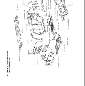
IMAGES PREVIEW OF THE MANUAL:
TABLE OF CONTENTS:
Mitsubishi Forklift FD60NM FD70NM MC Service Manual – PDF DOWNLOAD
Chapter 1 GENERAL INFORMATION
1 Model View 1-1
2 Applicable Truck Models 1-2
3 Serial Number Locations 1-3
4 Dimensions 1-4
5 Specifications 1-5
6 Performance 1-6
Chapter 2 COOLING SYSTEM
1 Specifications 2-1
2 Structure 2-2
3 Removing Fan Belt 2-3
31 Preparation 2-3
32 Removal Sequence 2-4
33 Suggestions for Removal 2-4
4 Inspecting and Adjusting Fan Belt 2-5
41 Inspecting Fan Belt 2-5
42 Adjusting Fan Belt Tension 2-5
5 Installing Fan Belt 2-5
51 Suggestions for Installation 2-5
6 Removing Oil Cooler and Radiator 2-6
61 Preparation 2-6
62 Removal Sequence 2-6
63 Installation 2-6
7 Inspecting Radiator 2-7
71 Radiator 2-7
72 Radiator Rubber Mount (Rubber Cushion) 2-7
73 Radiator Cap 2-7
74 Connecting Hoses 2-7
75 Coolant 2-8
76 Oil Cooler for Transmission 2-9
8 Troubleshooting 2-10
Chapter 3 ELECTRICAL SYSTEM
- Electrical Components and Wiring Outline 3-1
- Electrical Components and Wiring Diagram of Each Component 3-2
2 Console Box 3-6
21 Outline of Console Box 3-6
22 Disassembling Console Box 3-7
23 Assembling Console Box 3-7
3 Meter Panel 3-8
31 Disassembling Meter Panel 3-8
32 Assembling Meter Panel 3-8
33 Bulb Replacement 3-8
34 Warning Icons and Indicators 3-9
35 Hour Meter 3-10
36 Fuel Gauge 3-10
37 Connector 3-11
4 Switch Box 3-12
5 Main Electrical Components 3-13
51 Key Switch (Anti-Restart Switch) 3-13
52 Light Switch and Turn Signal Switch 3-14
53 Direction (FNR) Switch 3-15
54 Horn 3-16
55 Tank Unit 3-16
56 Stop Light Switch 3-17
57 Thermoswitch (T/C Oil) 3-18
58 Fuse Box 3-19
59 Relay Box 3-21
510 List of Lights 3-26
6 Battery and Maintenance 3-28
- Battery Specific Gravity Condition and Adjustment 3-28
- Relationship Between Electrolyte Specific Gravity and State of Charge 3-28
63 Precautions for Battery Charging 3-29
7 Wire Color 3-30
71 List of Wire Color Codes 3-30
8 Troubleshooting 3-31
81 Starter System 3-31
82 Gauges 3-31
83 Light Related Problems 3-32
84 Warning Device Problem 3-33
85 Battery-Related Problem 3-34
Chapter 4 POWER TRAIN
1 Removal and Installation 4-1
11 Overhead Guard, Covers, and Air Cleaner Element 4-2
12 Removing Harness 4-3
- Removing Driving Control Related Parts 4-4
- Removing Pipes/Hoses, Oil Cooler, and Radiator 4-5
- Removing Engine and Transmission Unit 4-6
16 Installation 4-7
17 Suggestions for Removing Harnesses and Cables
(Between Transmission and Frame) 4-9
2 Service Data 4-10
Chapter 5 POWERSHIFT TRANSMISSION
1 Specifications 5-1
2 Structure 5-2
21 Torque Converter 5-2
22 Transmission 5-3
23 Power Flow 5-4
24 Control Valve 5-5
25 Main Regulator Valve 5-6
26 Hydraulic Lines Diagram of Powershift Transmission 5-7
27 Automatic Gear Shifting Mechanism 5-8
28 Torque Converter Drive Control 5-9
3 Removal and Installation 5-10
31 Removal 5-10
32 Installation 5-10
4 Disassembling Torque Converter 5-11
41 Disassembly Sequence 5-11
42 Suggestions for Disassembly 5-11
5 Inspecting and Repairing Torque Converter 5-12
6 Assembling Torque Converter 5-14
61 Assembly Sequence 5-14
62 Suggestions for Assembly 5-15
7 Transmission (2nd Gear) 5-17
- Disassembling Control Valve and External Parts 5-17
- Disassembling Transmission Cover and Input/Counter/Output Shafts 5-18
73 Suggestions for Disassembly 5-19
74 Disassembling Stator Shaft and Oil Pump 5-20
75 Suggestions for Disassembly 5-21
76 Disassembling Input Shaft Subassembly 5-22
77 Suggestions for Disassembly 5-23
78 Disassembling Countershaft Subassembly 5-25
79 Suggestions for Disassembly 5-25
8 Inspection and Repair 5-26
81 Oil Pump 5-26
82 Stator Shaft 5-26
83 Friction Plate and Mating Plate 5-26
84 Input Shaft and Countershaft Clutch Drum 5-27
85 Input Shaft and Countershaft 5-28
86 Gears 5-28
87 Magnetic Strainer Assembly 5-28
88 Oil Seals of Transmission Cover and Torque Converter Case 5-28
9 Assembly 5-29
91 Input Shaft Subassembly (Countershaft Subassembly) 5-29
92 Suggestions for Assembly 5-30
93 Stator Shaft and Oil Pump 5-31
94 Suggestions for Assembly 5-32
95 Input Shaft, Countershaft, Output Shaft, and Transmission Cover 5-33
96 Suggestions for Assembly 5-34
97 Control Valve and External Parts 5-35
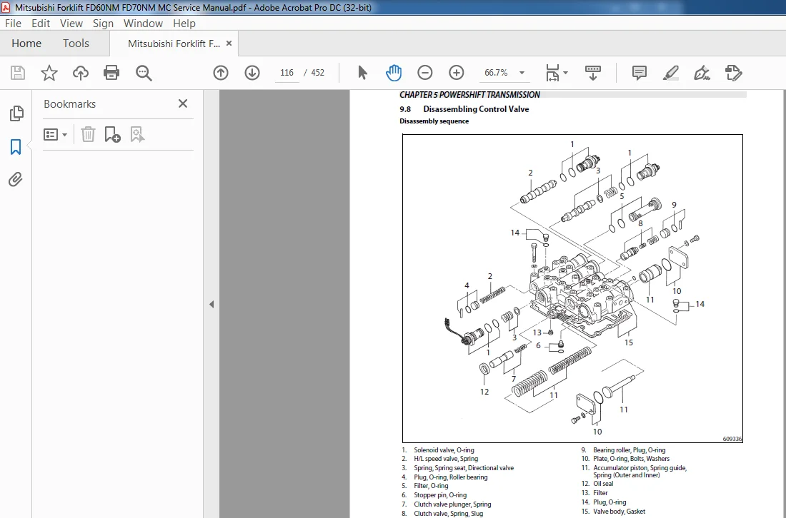
98 Disassembling Control Valve 5-36
99 Suggestions for Disassembly 5-37
910 Inspection and Repair 5-37
911 Assembly 5-38
912 Disassembling Main Regulator Valve 5-39
913 Inspecting and Correcting Main Regulator Valve 5-39
914 Assembling Main Regulator Valve 5-39
10 Adjustment 5-40
101 Measuring Oil Pressure 5-40
102 Testing Clutch Valve 5-41
103 Measuring Stall Speed 5-41
104 10 Meter Start Acceleration Test 5-42
105 Testing Automatic 2-Gear Transmission Functions 5-42
106 Adjusting Inching Pedal 5-43
11 Troubleshooting 5-45
12 Service Data 5-50
121 Stall Speed 5-50
122 Pump Boss 5-50
123 Pilot Boss 5-51
124 Oil Pump 5-51
125 Stator 5-52
126 Flexible Plate 5-53
127 Clutches 5-54
128 Input Shaft, Countershaft, and Transmission Cover 5-55
129 Backlash of Gears 5-56
1210 Control Valve 5-57
1211 Main Regulator Valve 5-58
1212 Inching Pedal Control 5-58
Chapter 6 FRONT AXLE AND REDUCTION DIFFERENTIAL
1 Specifications 6-1
2 Structure 6-2
3 Removing Front Wheels 6-3
31 Preparation 6-3
32 Removal Sequence 6-3
33 Suggestions for Removal 6-3
4 Installing Front Wheels 6-4
41 Suggestions for Installation 6-4
- Removing Front Axle and Reduction Differential Assembly 6-5
51 Preparation 6-5
52 Removal Sequence 6-5
53 Suggestions for Removal 6-6
- Installing Front Axle and Reduction Differential Assembly 6-6
61 Suggestions for Installation 6-6
- Disassembling and Assembling Front Axle 6-7
71 Preparation 6-7
72 Disassembly Sequence 6-7
73 Suggestions for Disassembly 6-8
- Inspecting and Repairing Front Axle 6-9
9 Assembling Front Axle 6-11
91 Preparation 6-11
92 Assembly Sequence 6-11
93 Suggestions for Assembly 6-12
- Disassembling Reduction Differential 6-14
101 Preparation 6-14
102 Disassembly Sequence 6-15
103 Suggestions for Disassembly 6-16
- Inspecting and Repairing Reduction Differential 6-17
12 Assembling Reduction Differential 6-18
121 Assembly Sequence 6-18
122 Suggestions for Assembly 6-19
13 Troubleshooting 6-24
14 Service Data 6-25
141 Front Axle 6-25
142 Reduction Differential 6-26
Chapter 7 REAR AXLE
1 Specifications 7-1
2 Structure 7-2
21 Rear Axle 7-2
22 Power Steering Cylinder 7-3
3 Removing Rear Wheels 7-4
31 Preparation 7-4
32 Removal Sequence 7-4
33 Suggestions for Removal 7-5
4 Installing Rear Wheels 7-5
41 Suggestions for Installation 7-5
5 Removing Rear Axle 7-6
51 Preparation 7-6
52 Removal Sequence 7-6
6 Installing Rear Axle 7-8
61 Suggestions for Installation 7-8
7 Disassembling Rear Axle Assembly 7-9
71 Disassembly Sequence 7-9
72 Suggestions for Removal 7-10
8 Assembling Rear Axle 7-12
81 Assembly Sequence 7-12
- Disassembling Power Steering Cylinder 7-17
91 Disassembly Sequence 7-17
92 Suggestions for Disassembly 7-18
- Inspecting and Adjusting Power Steering Cylinder 7-19
- Assembling Power Steering Cylinder 7-20
111 Assembly Sequence 7-20
112 Suggestions for Assembly 7-20
12 Adjustment 7-22
121 Measuring Minimum Turning Radius 7-22
13 Troubleshooting 7-23
14 Service Data 7-24
141 Rear Axle 7-24
142 Power Steering Cylinder 7-25
Chapter 8 BRAKE SYSTEM
1 Specifications 8-1
2 Structure 8-2
21 Brake System 8-2
22 Wheel Brake 8-3
23 Brake Booster 8-4
24 Master Cylinder 8-5
25 Parking Brake 8-6
3 Disassembly and Assembly 8-7
31 Disassembling Wheel Brake 8-7
32 Inspecting and Repairing Wheel Brake 8-9
33 Assembling Wheel Brake 8-11
34 Disassembling Wheel Cylinder 8-14
35 Inspecting and Repairing Wheel Cylinder 8-15
36 Assembling Wheel Cylinder 8-15
37 Disassembling Master Cylinder 8-16
38 Inspecting and Repairing Master Cylinder 8-17
39 Assembling Master Cylinder 8-18
310 Inspecting and Repairing Master Cylinder 8-18
311 Disassembling Parking Brake 8-19
312 Inspecting and Repairing Parking Brake 8-19
313 Assembling Parking Brake 8-20
314 Adjusting Parking Brake Lever 8-20
- Inspecting and Repairing Parking Brake Lever 8-20
- Checking Parking Brake Lever Operating force 8-20
4 Adjustment and Actuation Test 8-21
41 Wheel Brake 8-21
42 Testing Brake Booster Actuation 8-24
43 Vacuum Pump and Vacuum Pump Controller Actuation Test 8-25
44 Parking Brake 8-26
5 Troubleshooting 8-27
6 Service Data 8-29
61 Brake System 8-29
62 Master Cylinder 8-30
63 Wheel Cylinder 8-31
64 Wheel Brake 8-32
65 Parking Brake Lever 8-33
66 Parking Brake 8-33
Chapter 9 STEERING SYSTEM
1 Structure and Functions 9-1
11 General 9-1
12 Steering Valve 9-2
13 Steering Column 9-4
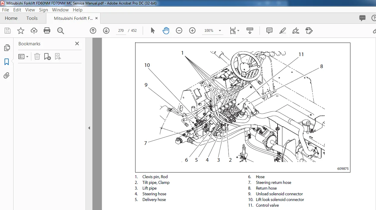
- Disassembling and Assembling Pipes and Hoses 9-6
- Suggestions for Disassembly and Assembly 9-6
- Disassembling Steering Wheel and Steering Valve 9-7
31 Disassembly Sequence 9-7
32 Suggestions for Disassembly 9-8
- Installing Steering Wheel and Steering Valve 9-9
41 Suggestions for Installation 9-11
42 Inspection After Installation 9-12
5 Removing Steering Valve 9-13
6 Installing Steering Valve 9-13
7 Disassembling Tilt Lock Lever 9-16
8 Assembling Tilt Lock Lever 9-17
9 Disassembling Steering Valve 9-18
91 Disassembly Sequence 9-18
92 Suggestions for Steering Valve Disassembly 9-19
93 Inspection After Disassembly 9-21
10 Assembling Steering Valve 9-22
101 Preparation 9-22
102 Assembly Sequence of Steering Valve 9-22
103 Suggestions for Assembly 9-23
11 Troubleshooting 9-27
12 Service Data 9-28
Chapter 10 HYDRAULIC SYSTEM
1 Specifications 10-1
2 Structure 10-2
21 Hydraulic Line 10-2
22 Hydraulic Tank 10-3
23 Gear Pump 10-4
24 Control Valve 10-5
25 Lift Cylinder 10-12
26 Tilt Cylinder 10-13
27 Flow Regulator Valve 10-14
28 Down Safety Valve 10-15
29 Hydraulic System Diagram 10-16
3 Removing Gear Pump 10-17
31 Preparation 10-17
32 Removal Sequence 10-17
33 Suggestions for Removal 10-17
4 Removing Control Valve 10-18
41 Removal Sequence 10-18
5 Removing Lift Cylinders 10-19
51 Removal Sequence 10-19
6 Removing Tilt Cylinders 10-21
61 Preparation (#3) 10-21
62 Removal Sequence 10-21
7 Disassembling Gear Pump 10-22
71 Disassembly Sequence 10-22
72 Suggestions for Disassembly 10-23
8 Inspecting and Repairing Gear Pump 10-24
9 Assembling Gear Pump 10-25
91 Assembly Sequence 10-25
92 Suggestions for Assembly 10-26
10 Disassembling Lift Cylinder 10-27
101 Disassembly Sequence 10-27
102 Suggestions for Disassembly 10-28
11 Inspecting and Repairing Lift Cylinder 10-29
12 Assembling Lift Cylinders 10-31
121 Assembly Sequence 10-31
122 Suggestions for Assembly 10-31
13 Disassembling Tilt Cylinder 10-32
131 Disassembly Sequence 10-32
132 Suggestions for Disassembly 10-32
14 Inspecting and Repairing Tilt Cylinder 10-33
15 Assembling Tilt Cylinder 10-35
151 Assembly Sequence 10-35
152 Suggestions for Assembly 10-35
16 Disassembling Flow Regulator Valve 10-36
161 Disassembly Sequence 10-36
17 Inspecting and Repairing Flow Regulator Valve 10-37
18 Assembling Flow Regulator Valve 10-37
19 Disassembling Down Safety Valve 10-37
191 Disassembly Sequence 10-37
20 Inspecting Down Safety Valve 10-37
21 Assembling Down Safety Valve 10-37
22 Inspecting and Adjusting Hydraulic System 10-38
221 Hydraulic Oil 10-38
222 Suction Strainer and Return Filter 10-38
223 Test Operation of Gear Pump 10-38
224 Control Valve 10-39
225 Adjusting Priority Relief Valve 10-41
226 Adjusting Overload Relief Valve (Option) 10-42
227 Adjusting Flow Regulator Valve 10-42
23 Tests 10-43
231 Vertical Drift Test 10-43
232 Tilt Drift Test 10-43
24 Troubleshooting 10-44
25 Service Data 10-48
251 Gear Pump 10-48
252 Control Valve 10-49
253 Hydraulic Tank 10-50
254 Flow Regulator Valve 10-50
255 Lift Cylinder 10-51
256 Tilt Cylinder 10-52
Chapter 11 MAST AND FORKS
1 Simplex Mast 11-1
11 Mast System 11-1
12 Structure and Functions 11-2
- Removal Sequence of Mast and Lift Bracket Assembly 11-5
- Suggestions for Removing Mast and Lift Bracket Assembly 11-6
- Suggestions for Installing Mast and Lift Bracket Assembly 11-9
- Disassembly Sequence of Mast and Lift Bracket 11-10
- Suggestions for Disassembling Mast and Lift Bracket 11-11
18 Inspecting Mast and Lift Bracket 11-12
19 Assembly Sequence of Lift Bracket Roller 11-14
110 Adjusting Lift Bracket Clearance 11-16
111 Installing Outer/Inner Mast Rollers 11-18
112 Installing Mast Strips 11-19
113 Installing Lift Cylinders 11-20
114 Connecting Chains 11-21
115 Installing Hydraulic Lines 11-22
116 Removing and Installing Mast Rollers and Strips Without
Removing Mast From Forklift Truck 11-24
117 Inspection and Adjustment 11-25
118 Inspecting Forks 11-25
119 Inspecting and Adjusting Chain Tension 11-27
120 Measuring Chain Elongation 11-28
121 Adjusting Clearance Between Lift Bracket Roller and Inner Mast 11-29
122 Adjusting Mast Roller Clearance 11-30
123 Inspecting and Adjusting Mast Strip Clearance 11-32
124 Adjusting Mast Tilt Angle 11-32
125 Inspecting and Adjusting Right and Left Lift Cylinder Stroke 11-33
126 Troubleshooting 11-34
127 Service Data 11-35
2 Triplex Mast 11-37
21 Mast System 11-37
22 Structure and Functions 11-38
- Removal Sequence of Mast and Lift Bracket Assembly 11-41
- Suggestions for Removing Mast and Lift Bracket Assembly 11-42
- Suggestions for Installing Mast and Lift Bracket Assembly 11-45
- Disassembly Sequence of Mast and Lift Bracket 11-46
- Preparation for Disassembling Mast and Lift Bracket 11-46
- Suggestions for Disassembling Mast and Lift Bracket 11-47
29 Inspecting Mast and Lift Bracket 11-48
210 Assembly Sequence of Lift Bracket Roller 11-50
211 Adjusting Lift Bracket Clearance 11-52
212 Installing Outer/Middle/Inner Mast Rollers 11-54
213 Installing Mast Strips 11-55
214 Installing Second Lift Cylinder 11-56
215 Installing First Lift Cylinder 11-57
216 Connecting Chains 11-58
217 Installing Hydraulic Lines 11-59
218 Removing and Installing Mast Rollers and Strips Without
Removing Mast From Forklift Truck 11-61
219 Inspection and Adjustment 11-63
220 Inspecting Forks 11-63
221 Inspecting and Adjusting Chain Tension 11-65
222 Measuring Chain Elongation 11-66
223 Adjusting Clearance Between Lift Bracket Roller and Inner Mast 11-67
224 Adjusting Mast Roller Clearance 11-68
225 Inspecting and Adjusting Mast Strip Clearance 11-72
226 Adjusting Mast Tilt Angle 11-72
227 Inspecting and Adjusting Right and Left Second Lift Cylinder Stroke 11-73
228 Troubleshooting 11-74
229 Service Data 11-75
Chapter 12 SIDE SHIFTER
1 Applicable Attachment Type 12-1
2 Specifications 12-1
3 Structure 12-2
4 Removing Side Shifter 12-3
41 Preparation 12-3
42 Removing Side Shifter Assembly 12-3
43 Suggestions for Removal 12-4
5 Installing Side Shifter 12-5
51 Suggestions for Installation 12-5
- Disassembling Side Shifter Assembly 12-6
61 Preparation 12-6
62 Disassembly Sequence 12-6
63 Suggestions for Disassembly 12-7
- Inspecting and Repairing Side Shifter Assembly 12-7
8 Assembling Side Shifter Assembly 12-7
81 Suggestions for Assembly 12-7
- Disassembling Side Shifter Cylinder 12-8
91 Disassembly Sequence 12-8
92 Suggestions for Disassembly 12-8
- Inspecting and Repairing Side Shifter Cylinder 12-9
11 Assembling Side Shifter Cylinder 12-10
111 Assembly Sequence 12-10
112 Suggestions for Assembly 12-10
12 Inspecting and Adjusting Side Shifter Cylinder 12-10
13 Troubleshooting 12-11
14 Service Data 12-12
141 Side Shifter Cylinder 12-12
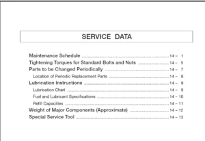
Chapter 13 SERVICE DATA
1 Maintenance Schedule 13-1
2 Tightening Torques for Standard Bolts and Nuts 13-6
21 Metric Fine Thread 13-6
22 Metric Coarse Thread 13-8
3 Periodic Replacement Parts 13-10
31 Safety Critical Parts 13-11
4 Lubrication Schedule 13-13
41 Lubrication Chart 13-13
42 Fuel and Lubricant Specifications 13-14
43 Adjustment Value and Oil Capacity 13-15
5 Weight of Major Devices 13-17
6 Special Tools 13-18
61 Special Service Tools 13-18
Chapter 14 HOW TO READ CIRCUIT DIAGRAMS
1 Description of Circuit Diagrams 14-1
11 Circuit Diagrams 14-1
12 Connector Diagrams 14-1
2 How to Read Circuit Diagrams 14-2
21 Symbols 14-3
22 Sheet Symbol 14-6
23 Connecting Lines 14-7
24 Equipment 14-8
25 Relay Contactor and Coil 14-9
26 Connectors 14-9
27 Indication of Connecting Line 14-10
28 Indication of GND (Earth) 14-10
29 Indication of Another Specification 14-11
3 How to Read Connector Diagrams 14-12
4 Abbreviation 14-14
Chapter 15 CIRCUIT DIAGRAM
MITSUBISHI FORKLIFT FD60NM FD70NM MC SERVICE MANUAL – PDF DOWNLOAD:
PLEASE NOTE:
- This is the same manual used by the DEALERSHIPS to SERVICE your vehicle.
- The manual can be all yours – Once payment is complete, you will be taken to the download page from where you can download the manual. All in 2-5 minutes time!!
- Need any other service / repair / parts manual, please feel free to contact us at heydownloadss @gmail.com . We may surprise you with a nice offer
Damir Ismael –
VERY SIMPLE EASY TRANSACTION. GREAT PRODUCT