Mitsubishi L200 Triton 4D56 4M41 Engine Shop Manual 2005 – 2011 – PDF DOWNLOAD
Original price was: $36.95.$20.95Current price is: $20.95.
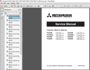
Mitsubishi L200 Triton 4D56 4M41 Engine Shop Manual 2005 – 2011
Description
Mitsubishi L200 Triton 4D56 4M41 Engine Shop Manual 2005 – 2011
FILE DETAILS:
LANGUAGE:ENGLISH
PAGES:52
DOWNLOADABLE:YES
FILE TYPE:PDF
MITSUBISHI L200 TRITON 4D56 4M41 ENGINE SHOP MANUAL 2005 – 2011 – PDF DOWNLOAD:
IMAGES PREVIEW OF THE MANUAL:
DESCRIPTION:
Mitsubishi L200 Triton 4D56 4M41 Engine Shop Manual 2005 – 2011
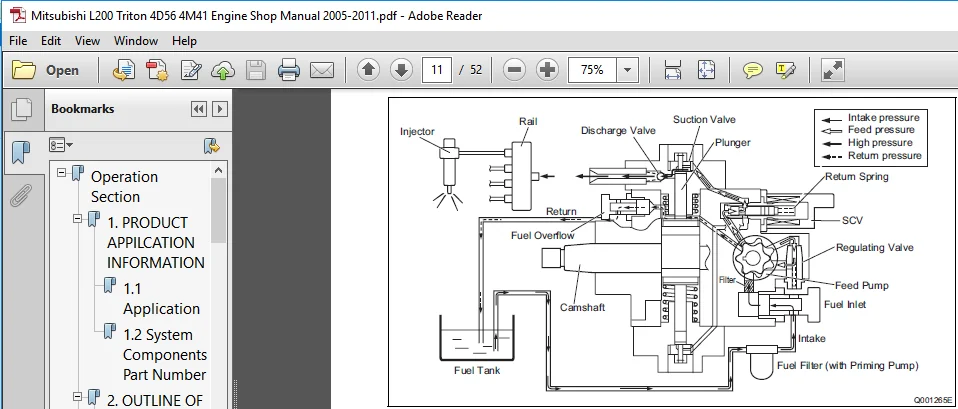
Common Rail System Characteristics
- The common rail system uses a type of accumulation chamber called a rail to store pressurized fuel, and injectors that contain electronically controlled solenoid valves to inject the pressurized fuel into the cylinders. Because the engine ECU controls the injection system (injection pressure, injection rate, and injection timing), the injection system is independent, and thus unaffected by the engine speed or load.
- This ensures a stable injection pressure at all times, particularly in the low engine speed range, and dramatically decreases the amount of black smoke ordinarily emitted by a diesel engine during start-up and acceleration. As a result, exhaust gas emissions are cleaner and reduced, and higher power output is achieved.
Features of Injection Control
(1) Injection Pressure Control
• Enables high-pressure injection even at low engine speeds.
• Optimizes control to minimize particulate matter and NOx emissions.
(2) Injection Timing Control
• Enables finely tuned optimized control in accordance with driving conditions.
(3) Injection Rate Control
• Pilot injection control injects a small amount of fuel before the main injection.
TABLE OF CONTENTS:
Mitsubishi L200 Triton 4D56 4M41 Engine Shop Manual 2005 – 2011
Operation Section........................................................................ 6
	1. PRODUCT APPILCATION INFORMATION................................................... 6
		1.1 Application.................................................................. 6
		1.2 System Components Part Number................................................ 6
	2. OUTLINE OF SYSTEM................................................................. 7
		2.1 Common Rail System Characteristics........................................... 7
		2.2 Features of Injection Control................................................ 7
		2.3 Comparison to the Conventional System........................................ 8
		2.4 Composition.................................................................. 8
		2.5 Operation.................................................................... 9
		2.6 Fuel System.................................................................. 9
		2.7 Control System............................................................... 9
	3. SUPPLY PUMP.......................................................................11
		3.1 Outline......................................................................11
		3.2 Exterior View Diagram........................................................12
		3.3 Supply Pump Internal Fuel Flow...............................................12
		3.4 Construction of Supply Pump..................................................13
		3.5 Operation of the Supply Pump.................................................14
	4. SUPPLY PUMP COMPONENT PARTS.......................................................16
		4.1 Feed Pump....................................................................16
		4.2 SCV ( Suction Control Valve )................................................16
		4.3 Fuel Temperature Sensor......................................................18
	5. RAIL..............................................................................19
		5.1 Outline......................................................................19
	6. RAIL COMPONENTS PARTS.............................................................20
		6.1 Rail Pressure Sensor (Pc Sensor).............................................20
		6.2 Pressure limiter.............................................................20
	7. INJECTOR (G2 TYPE)................................................................21
		7.1 Outline......................................................................21
		7.2 Characteristics..............................................................21
		7.3 Exterior View Diagram........................................................22
		7.4 Construction.................................................................23
		7.5 Operation....................................................................23
		7.6 QR Codes.....................................................................24
		7.7 Injector Actuation Circuit...................................................26
	8. OPERATION OF CONTROL SYSTEM COMPONENTS............................................27
		8.1 Engine Control System Diagram................................................27
		8.2 Engine ECU (Electronic Control Unit).........................................27
		8.3 Cylinder Recognition Sensor (TDC)............................................28
		8.4 Turbo Pressure Sensor........................................................28
		8.5 Mass Air Flow Sensor.........................................................29
		8.6 Electronic Control Throttle..................................................30
	9. VARIOUS TYPES OF CONTROL..........................................................32
		9.1 Outline......................................................................32
		9.2 Fuel Injection Rate Control Function.........................................32
		9.3 Fuel Injection Quantity Control Function.....................................32
		9.4 Fuel Injection Timing Control Function.......................................32
		9.5 Fuel Injection Pressure Control Function (Rail Pressure Control Function)....32
	10. FUEL INJECTION QUANTITY CONTROL..................................................33
		10.1 Outline.....................................................................33
		10.2 Injection Quantity Calculation Method.......................................33
		10.3 Set Injection Quantities....................................................33
	11. FUEL INJECTION TIMING CONTROL....................................................37
		11.1 Ouline......................................................................37
		11.2 Main and Pilot Injection Timing Control.....................................37
		11.3 Microinjection Quantity Learning Control....................................38
	12. FUEL INJECTION RATE CONTROL......................................................40
		12.1 Outline.....................................................................40
	13. FUEL INJECTION PRESSURE CONTROL..................................................41
		13.1 Fuel Injection Pressure.....................................................41
	14. DIAGNOSTIC TROUBLE CODES (DTC)...................................................42
		14.1 About the Codes Shown in the Table..........................................42
		14.2 Diagnostic Trouble Code Details.............................................42
	15. EXTERNAL WIRING DIAGRAM..........................................................47
		15.1 Engine ECU External Wiring Diagram..........................................47
		15.2 Engine ECU Connector Diagram................................................48
PLEASE NOTE:
- This is not a physical manual but a digital manual – meaning no physical copy will be couriered to you. The manual can be yours in the next 2 mins as once you make the payment, you will be directed to the download page IMMEDIATELY.
- This is the same manual used by the dealers inorder to diagnose your vehicle of its faults.
- Require some other service manual or have any queries: please WRITE to us at [email protected]
Maximiliano Waylon –
Payment is not going through