★ TRUSTED BY 321,897+ PROFESSIONALS WORLDWIDE
🏢
Trusted Business
Verified & Licensed
🛡️
Virus Free Files
100% Safe Downloads
🔒
Secure Payment
SSL Protected
Instant Delivery
Available Immediately
Sale!

MTU 8V 12V 16V 2000 M40A M40B M41A M41B Diesel Engine Operating Instructions Manual MS150031/06E

Original price was: $39.95.Current price is: $24.95.

Official factory operating instructions manual for MTU Series 2000 marine and industrial diesel engines (8V, 12V, and 16V configurations, M40A/B and M41A/B). Features full operating procedures, LOP control operations, complete ECU fault codes, maintenance tasks, and technical specifications in PDF format.

Instant PDF Download
Available immediately
💾
Save to Your Device
Download & keep forever
🛡️
Antivirus Scanned
100% virus-free
🌍
Trusted Worldwide
175,000+ customers

Description

Comprehensive Operation & Maintenance Guide for MTU Series 2000 Diesel Engines

The MTU 8V 12V 16V 2000 M40A M40B M41A M41B Diesel Engine Operating Instructions Manual MS150031/06E provides complete technical direction, commissioning protocols, and ongoing maintenance guidelines for marine propulsion and power generation installations powered by MTU Series 2000 engines. Covering 8-cylinder, 12-cylinder, and 16-cylinder variants in 90° V configurations across application groups 3B and 3C, this document provides authorized procedures directly from MTU Friedrichshafen GmbH to keep your machinery operating reliably and safely.

File Details

  • Manual Type: Operating Instructions
  • Brand: MTU Friedrichshafen GmbH
  • Document Number: MS150031/06E
  • Publication Date: 2016-10
  • Applicable Models: 8V2000M40A, 8V2000M40B, 8V2000M41A, 8V2000M41B, 12V2000M40A, 12V2000M40B, 12V2000M41A, 12V2000M41B, 16V2000M40A, 16V2000M40B, 16V2000M41A, 16V2000M41B
  • Language: English
  • Page Count: 242
  • Format: Digital PDF

Complete PDF Bookmark Tree

Complete Bookmarks

The complete bookmarks in the “MTU 8V 12V 16V 2000 M40A M40B M41A M41B Diesel Engine Operating Instructions Manual MS150031/06E” are as follows:

Operating Instructionsp. 1
Table of Contentsp. 3
1 Safetyp. 6
1.1 Important provisions for all productsp. 6
1.2 Personnel and organizational requirementsp. 7
1.3 Transportationp. 8
1.4 Safety regulations for maintenance and repair workp. 11
1.5 Fire prevention and environmental protection, fluids and lubricants, indirect materialsp. 15
1.6 Standards for safety notices in the textp. 17
2 General Informationp. 18
2.1 Engine side and cylinder designationsp. 18
2.2 Product descriptionp. 19
2.3 Series 2000 M40A/B – M41A/Bp. 27
2.4 Sensors and actuators – Overviewp. 28
2.5 Sensors and actuators – Overviewp. 32
3 Technical Datap. 42
3.1 8V 2000 M40A engine data: engine-mounted heat exchanger, reference conditions: 25 °C intake air temperaturep. 42
3.2 8V 2000 M40A engine data: separate heat exchanger, reference conditions: 25 °C intake air temperaturep. 45
3.3 8V 2000 M40B engine data, engine-mounted heat exchanger, reference condition: 25 °C intake air temperaturep. 48
3.4 8V 2000 M40B engine data, separate heat exchanger, reference condition: 25 °C intake air temperaturep. 51
3.5 8V 2000M41A engine data: Engine-mounted heat exchangerp. 54
3.6 8V 2000M41A engine data: Remote heat exchangerp. 57
3.7 8V 2000M41B engine data: Engine-mounted heat exchangerp. 60
3.8 8V 2000M41B engine data: Remote heat exchangerp. 63
3.9 12V 2000 M40A engine data: Engine-mounted heat exchanger, reference conditions: 45 °C intake air temperaturep. 66
3.10 12V 2000 M40A engine data: Engine-mounted heat exchanger, reference conditions: 25 °C intake air temperaturep. 69
3.11 12V 2000 M40A engine data: Separate heat exchanger, reference conditions: 25 °C intake air temperaturep. 72
3.12 12V 2000 M40A engine data: Separate heat exchanger, reference conditions: 45 °C intake air temperaturep. 75
3.13 16V 2000 M40A engine data: engine-mounted heat exchanger, reference conditions: 25 °C intake air temperaturep. 78
3.14 16V 2000 M40A engine data: engine-mounted heat exchanger, reference conditions: 45 °C intake air temperaturep. 81
3.15 16V 2000 M40A engine data: separate heat exchanger, reference conditions: 25 °C intake air temperaturep. 84
3.16 16V 2000 M40A engine data: separate heat exchanger, reference conditions: 45 °C intake air temperaturep. 87
3.17 16V 2000 M40B engine data, engine-mounted heat exchanger, reference condition: 45 °C intake air temperaturep. 90
3.18 16V 2000 M40B engine data, engine-mounted heat exchanger, reference condition: 25 °C intake air temperaturep. 93
3.19 16V 2000 M40B engine data, separate heat exchanger, reference condition: 45 °C intake air temperaturep. 96
3.20 16V 2000 M40B engine data, separate heat exchanger, reference condition: 25 °C intake air temperaturep. 99
3.21 ENGINE DATA 12V 2000M41A/Bp. 102
3.22 ENGINE DATA 16V 2000M41A/Bp. 105
3.23 Firing orderp. 108
3.24 Engine – Main dimensionsp. 109
4 Operationp. 110
4.1 LOP – Control elementsp. 110
4.2 Putting the engine into operation (out-of-service period > 3 months)p. 112
4.3 Putting the engine into operation after scheduled out-of-service periodp. 113
4.4 Starting the engine from LOP (without BlueLine automation system)p. 114
4.5 Operational monitoringp. 115
4.6 Stopping the engine at the LOPp. 116
4.7 Emergency engine stop from LOPp. 117
4.8 After stopping the enginep. 118
4.9 Plant – Cleaningp. 119
5 Maintenancep. 120
5.1 Maintenance task reference table [QL1]p. 120
6 Troubleshootingp. 121
6.1 ECU alarmsp. 121
6.2 Troubleshootingp. 131
6.3 LOP fault messagesp. 134
7 Task Descriptionp. 139
7.1 SOLASp. 139
7.1.1 SOLAS shielding as per MTN 5233 – Installationp. 139
7.1.2 SOLAS shielding – Installationp. 140
7.1.3 Installation locations for SOLAS shieldingp. 141
7.2 Enginep. 146
7.2.1 Engine – Barring manuallyp. 146
7.2.2 Engine – Cranking on starting systemp. 147
7.3 Cylinder Linerp. 148
7.3.1 Cylinder liner – Endoscopic examinationp. 148
7.3.2 Cylinder liner – Instructions and comments on endoscopic and visual examinationp. 150
7.4 Crankcase Breatherp. 152
7.4.1 Crankcase breather – Oil separator replacement, diaphragm check and replacementp. 152
7.4.2 Crankcase breather – Cleaning oil pre-separator elementp. 154
7.5 Valve Drivep. 155
7.5.1 Valve clearance – Check and adjustmentp. 155
7.5.2 Cylinder head cover – Removal and installationp. 158
7.6 Injection Pump / HP Pumpp. 159
7.6.1 Injection pump – Replacementp. 159
7.6.2 Injection pump – Removal and installationp. 160
7.7 Injection Valve / Injectorp. 163
7.7.1 Injector – Replacementp. 163
7.7.2 Injector – Removal and installationp. 164
7.8 Fuel Systemp. 167
7.8.1 HP fuel line – Pressure pipe neck replacementp. 167
7.8.2 Fuel – Drainingp. 169
7.8.3 Fuel system – Ventingp. 170
7.9 Fuel Filterp. 172
7.9.1 Fuel filter – Replacementp. 172
7.9.2 Fuel prefilter – Differential pressure check and adjustment of gaugep. 174
7.9.3 Fuel prefilter – Drainingp. 176
7.9.4 Fuel prefilter – Flushingp. 179
7.9.5 Fuel prefilter – Filter element replacementp. 183
7.10 Charge-Air Coolingp. 187
7.10.1 Intercooler ‒ Checking condensate drain line for coolant discharge and obstructionp. 187
7.11 Air Filterp. 188
7.11.1 Air filter – Replacementp. 188
7.11.2 Air filter – Removal and installationp. 189
7.12 Air Intakep. 190
7.12.1 Service indicator – Signal ring position checkp. 190
7.13 Starting Equipmentp. 191
7.13.1 Starter – Condition checkp. 191
7.14 Lube Oil System, Lube Oil Circuitp. 192
7.14.1 Engine oil – Level checkp. 192
7.14.2 Engine oil – Changep. 193
7.15 Oil Filtration / Coolingp. 194
7.15.1 Oil dipstick — Markingp. 194
7.15.2 Engine oil filter – Replacementp. 195
7.15.3 Centrifugal oil filter and filter sleeve – Cleaning and replacementp. 197
7.16 Coolant Circuit, General, High-Temperature Circuitp. 200
7.16.1 Drain and venting pointsp. 200
7.16.2 Engine coolant – Level checkp. 205
7.16.3 Engine coolant – Changep. 206
7.16.4 Engine coolant – Drainingp. 207
7.16.5 Engine coolant ‒ Fillingp. 208
7.16.6 HT coolant pump ‒ Relief bore checkp. 209
7.16.7 Engine coolant – Sample extraction and analysisp. 210
7.17 Raw Water Pump with Connectionsp. 211
7.17.1 Raw water pump – Relief bore checkp. 211
7.18 Belt Drivep. 212
7.18.1 Drive belt – Condition checkp. 212
7.19 Battery-Charging Generatorp. 213
7.19.1 Battery-charging generator drive – Drive belt check and adjustmentp. 213
7.19.2 Battery-charging generator drive – Drive belt replacementp. 215
7.20 Engine Mounting / Supportp. 217
7.20.1 Engine mounting – Checking condition of resilient mountsp. 217
7.21 Wiring (General) for Engine/Gearbox/Unitp. 218
7.21.1 Engine cabling – Checkp. 218
7.22 Accessories for (Electronic) Engine Governor / Control Systemp. 219
7.22.1 Engine Control Unit and connectors – Cleaningp. 219
7.22.2 EMU and connectors – Cleaningp. 220
7.22.3 Start interlock limit switch – Checkp. 221
7.22.4 ECU – Plug connections checkp. 222
7.22.5 Engine monitoring unit, plug connections – Checkp. 223
7.22.6 Engine control system – Removal and installationp. 224
7.23 Emergency Instrumentation (Local Operating Panel)p. 225
7.23.1 LOP and connectors – Cleaningp. 225
7.23.2 LOP – Visual inspectionp. 226
7.23.3 LOP – Running test proceduresp. 228
8 Appendix Ap. 230
8.1 Abbreviationsp. 230
8.2 MTU Contact/Service Partnersp. 232
9 Appendix Bp. 233
9.1 Special Toolsp. 233
9.2 Indexp. 240

Chapters Covered

  • 1 Safety — 1.1 Important provisions for all products; 1.2 Personnel and organizational requirements; 1.3 Transportation and lifting procedures; 1.4 Safety regulations for maintenance and repair work; 1.5 Fire prevention, environmental protection, fluids and lubricants; 1.6 Standards for safety notices in the text
  • 2 General Information — 2.1 Engine side and cylinder designations (DIN ISO 1204 KS/KGS conventions); 2.2 Product description and functional subsystem breakdown; 2.3 Series 2000 M40A/B-M41A/B engine overview; 2.4 Sensors and actuators overhead and end-face layouts; 2.5 Sensors and actuators schematic overview for 12V and 16V configurations
  • 3 Technical Data — 3.1 through 3.20 Engine data for 8V, 12V, and 16V M40A/B configurations with engine-mounted and separate heat exchangers under 25°C and 45°C reference conditions; 3.21 Engine data 12V 2000M41A/B; 3.22 Engine data 16V 2000M41A/B; 3.23 Firing order tables; 3.24 Engine main dimensions and dimensional drawings
  • 4 Operation — 4.1 LOP Control elements and display interfaces; 4.2 Putting into operation after out-of-service periods exceeding 3 months; 4.3 Commissioning after scheduled out-of-service periods; 4.4 Starting engine from Local Operating Panel (LOP); 4.5 Operational monitoring and running checks; 4.6 Stopping engine at the LOP; 4.7 Emergency engine stop routines from LOP; 4.8 Procedures after stopping engine; 4.9 External plant cleaning
  • 5 Maintenance — 5.1 Maintenance task reference table [QL1] linking operating measures to standalone schedule tasks
  • 6 Troubleshooting — 6.1 ECU alarms and diagnostic code listings (4-digit code architecture); 6.2 Operational symptom troubleshooting; 6.3 LOP text fault messages and remedial actions
  • 7 Task Description — 7.1 SOLAS fire protection insulation and shielding installation (MTN 5233); 7.2 Engine barring and starter cranking; 7.3 Cylinder liner endoscopic examination criteria; 7.4 Crankcase breather oil separator and diaphragm renewal; 7.5 Valve clearance check and adjustment (cold: inlet 0.4 mm, exhaust 0.6 mm); 7.6 Fuel injection pump removal and installation; 7.7 Fuel injector replacement and extraction; 7.8 HP fuel lines and pressure pipe neck renewal; 7.9 Fuel duplex and prefilter maintenance, draining, flushing, and venting; 7.10 Charge-air cooler condensate check; 7.11 Air filter renewal; 7.12 Air intake service indicator inspection; 7.13 Electric and pneumatic starter checks; 7.14 Engine oil level inspection and oil drain/refill; 7.15 Oil filter and centrifugal filter sleeve maintenance; 7.16 Engine high-temperature coolant circuit draining, filling, and relief bore checks; 7.17 Raw water pump relief bore inspection; 7.18 Drive belt check; 7.19 Battery-charging generator belt adjustment and replacement; 7.20 Resilient engine mount measurement; 7.21 Engine wiring harness inspection; 7.22 ECU, EMU, and electronic governor connectors cleaning and inspection; 7.23 LOP emergency instrumentation visual check, lamp test, and overspeed trip testing
  • 8 Appendix A — 8.1 Technical abbreviations; 8.2 MTU contact and worldwide customer service partners
  • 9 Appendix B — 9.1 Special tools catalog; 9.2 Alphabetical subject index

This technical publication equips vessel engineers, power plant technicians, and certified mechanics with factory-approved instructions for the safe running, ongoing servicing, and component-level repair of MTU 2000 series diesel engines. From daily watchkeeping logs and fluid quality monitoring to full electronic diagnostic evaluations, it establishes clear benchmarks for operating integrity.

Operational Guidance & Electronic Control Integration

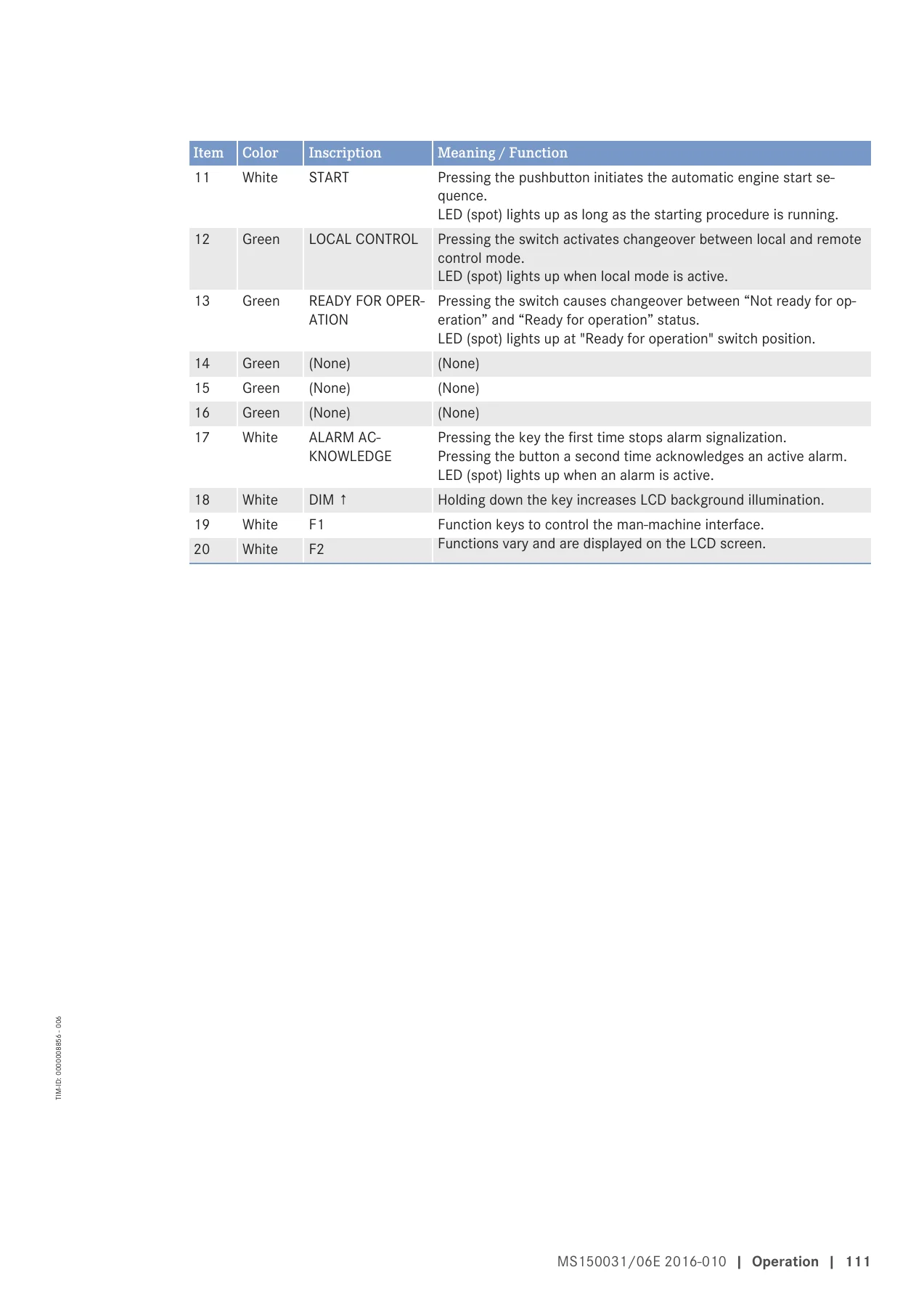
Operating high-output modern diesel machinery requires strict adherence to manufacturer operating profiles. This MTU 8V 12V 16V 2000 M40A M40B M41A M41B Diesel Engine Operating Instructions Manual MS150031/06E details the complete user interface for the Local Operating Panel (LOP) and the MDEC Engine Control Unit (ECU). Operators gain step-by-step procedures for pre-start verification, warm-up schedules, local control handover, overspeed trip tests, and emergency shutdowns. Crucially, the manual provides detailed troubleshooting flowcharts and decoded ECU alarm tables—including fault prefix interpretations for present, recent, and logged events—ensuring swift resolution of sensor deviations, temperature warnings, and pressure drops.

IMAGES PREVIEW

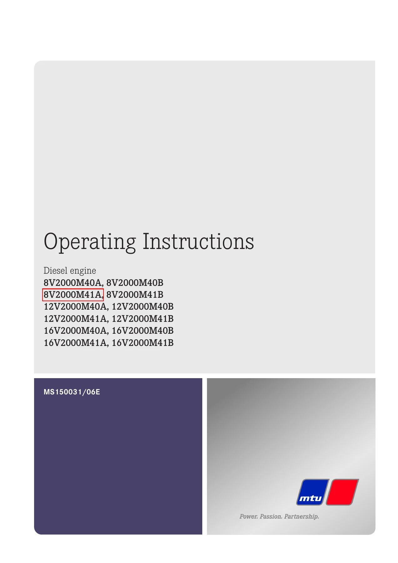
MTU 8V 12V 16V 2000 M40A M40B M41A M41B Diesel Engine Operating Instructions Manual MS150031/06E — PDF page 1 preview
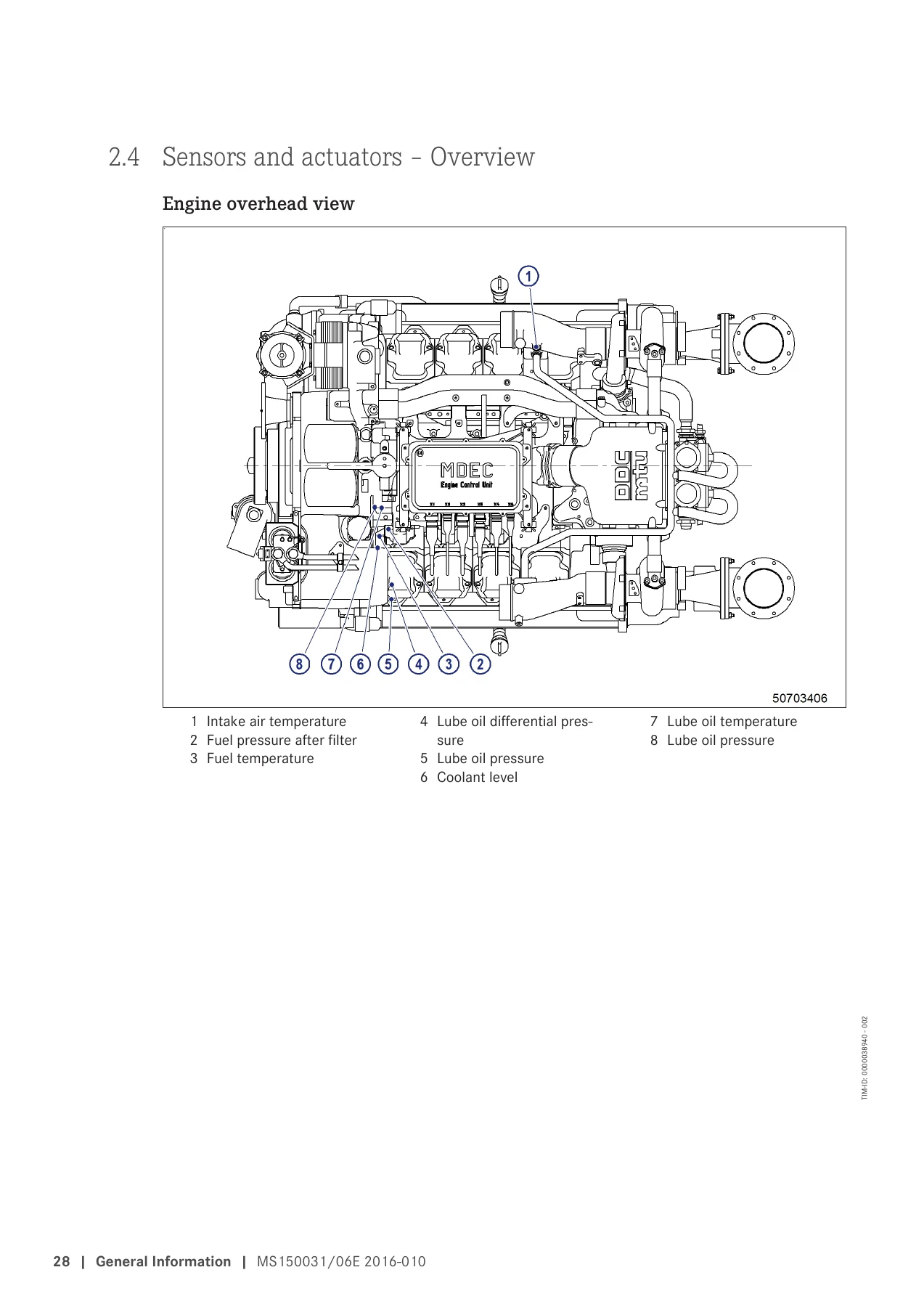
MTU 8V 12V 16V 2000 M40A M40B M41A M41B Diesel Engine Operating Instructions Manual MS150031/06E — PDF page 28 preview
MTU 8V 12V 16V 2000 M40A M40B M41A M41B Diesel Engine Operating Instructions Manual MS150031/06E — PDF page 111 preview

Practical Maintenance Tasks & Mechanical Service Procedures

Designed for hands-on maintenance, Section 7 walks mechanics through essential technical tasks with precise tightening torques, replacement criteria, and required special tool part numbers. Key procedures include:

  • Manual engine barring and starter-assisted cranking for fuel purging and diagnostic inspections
  • Precision cold valve clearance measurement and adjustment (0.40 mm intake, 0.60 mm exhaust) with two-crankshaft-position diagrams
  • Cylinder liner endoscopic inspection rubrics with full classification of honing patterns, burn marks, and wear limits
  • Removal, resealing, and torquing of individual high-pressure injection pumps (unit pump system) and fuel injectors
  • Service of switchable duplex fuel filters, water traps, and centrifugal lube oil filters including rotor cleaning and sleeve replacement
  • SOLAS-compliant fire protection shielding installation across fuel lines and pressurized lubrication connections under standard MTN 5233
  • Cooling circuit maintenance, covering split-circuit plate heat exchangers, thermostat operation, and raw water pump relief bore monitoring

Why This Manual Is Essential For Your Operation

Whether you are operating passenger vessels, commercial tugs, yachts, or continuous-duty gensets, having instant access to the correct engineering data prevents catastrophic mechanical failure, avoids unnecessary downtime, and keeps your propulsion systems compliant with marine classification society regulations. Guesswork on modern electronic diesel engines can lead to costly component damage; relying on the official MTU 8V 12V 16V 2000 M40A M40B M41A M41B Diesel Engine Operating Instructions Manual MS150031/06E ensures every setting, bolt torque, and fluid limit matches factory specifications.

This manual is provided as an instant PDF download immediately upon checkout. Compatible with laptops, tablets, smartphones, and desktop computers, the file is fully readable offline in the engine room or on the bridge. You can print individual pages or the complete 242-page reference manual for immediate use at the workbench.

Reviews

There are no reviews yet.

Be the first to review “MTU 8V 12V 16V 2000 M40A M40B M41A M41B Diesel Engine Operating Instructions Manual MS150031/06E”

What Our Customers Say

★★★★★ Live reviews from customers
Loading customer reviews...
0
    0
    Your Cart
    Your cart is emptyReturn to Shop
    🛒
    Recently Purchased
    🕒 verified order