
MTU BlueLine Series 2000 M92 M93 ECS-5 MCS-5 RCS-5 Marine Operation Workshop Installation Manual
Original price was: $36.95.$21.95Current price is: $21.95.
MTU BlueLine technical publication E532227/00E for Series 2000 M92 and M93 marine plants: functional description, operating instructions, workshop tasks, and installation and commissioning for ECS-5, MCS-5 and RCS-5.
Description
MTU BlueLine Series 2000 M92 M93 ECS-5 MCS-5 RCS-5 Marine Operation Workshop Installation Manual
This technical publication covers the BlueLine electronic propulsion-control suite used with MTU Series 2000 M92 and M93 marine engines. Publication number E532227/00E (footer marking 06-04) combines a functional description, operating instructions, a workshop manual, and installation and commissioning instructions for the Engine Control System ECS-5, Monitoring and Control System MCS-5, and Remote Control System RCS-5. The plant application is marine fixed-pitch propeller installations with one to four shafts and up to four control stands. An example engine designation shown in the document is 12V 2000 M92 (CR). Fault tables also address Engine Control Unit ECU 7 on Series 2000 CR engines.
The MTU BlueLine Series 2000 M92 M93 ECS-5 MCS-5 RCS-5 Marine Operation Workshop Installation Manual is written for operators, service technicians, and shipyard personnel who must run, diagnose, replace, wire, and commission the control hardware rather than overhaul the mechanical engine itself. Use it together with the separate engine operating and workshop publications referenced in the alarm and sensor procedures.
File Details
- Manual type: Functional description, operating instructions, workshop manual, installation and commissioning instructions
- Brand / models: MTU BlueLine for Series 2000 M92 and M93 marine propulsion plants
- Systems: ECS-5, MCS-5, RCS-5
- Language: English (commissioning card and copyright pages also printed in German, French, Spanish, Italian and Portuguese)
- Page count: 350
- File format: PDF
- Document number: E532227/00E
- Date marking: 06-04
- Publisher marking: MTU Friedrichshafen GmbH (cover also shows Detroit Diesel)
BlueLine Plant Layout
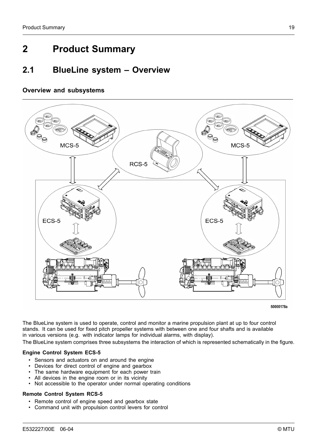
BlueLine is built as three cooperating subsystems. ECS-5 sits in or near the engine room with sensors and actuators on the engine and gearbox; it is not intended for day-to-day operator access. RCS-5 handles remote speed and gearbox-state commands from propulsion control levers. MCS-5 presents plant status, alarms and selected control functions at the helm stands. Data travels on a redundant CAN bus, with additional parallel wiring for safety-relevant signals. The same hardware set is used on each power train, arranged symmetrically port and starboard.
RCS-5 command hardware is selected by shaft count. ROS 9 serves single-shaft plants with mechanically coupled levers. ROS 7 (versions ROS 7-03 and ROS 7-04 differ only in lever length) is the twin-shaft command unit and may be paired on four-shaft plants. ROS 11 covers three shafts, with the middle pair of levers coupled. Rotary encoder modules ROS 10/S and ROS 10/P plus control panel ROS 10/T allow a customized lever, for example in a helmsman’s seat. Central evaluation is performed by one PIM 4 RCS control unit per power train on main control stand 1 (standard version up to two stands, extended version up to four).
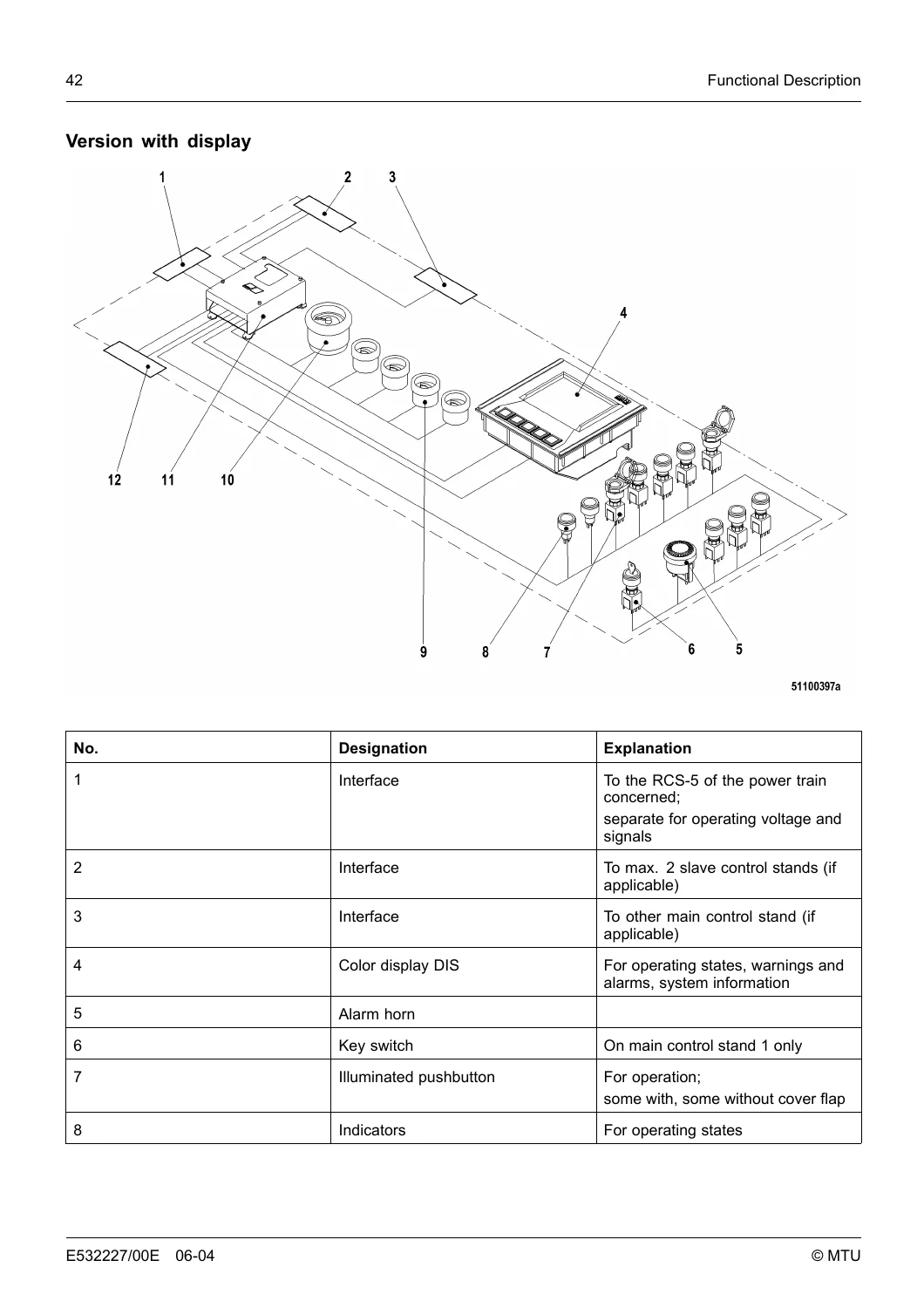
ECS-5 is offered in three local-control variants with the same core function: basic Local Operating Panel LOP with rotary switch, pushbutton and lamp; LOP plus Local Operating Station LOS with flat-screen display; or LOP with DIS display in the flap (an extra LOS is then not possible). Related units include Gear Control Units GCU 2, GCU 3 and GCU 6, engine governor ECU 7, auxiliary terminal box X010, microprocessor board MPU 29, and optional color display DIS with VDO OceanLine analog instruments and VDO horn.
Chapters Covered
- General Conditions — Safety: general conditions; personnel and organizational requirements; safety precautions when working on the engine; auxiliary materials, fire prevention and environmental protection; standards for warning notices
- Functional Description — Product Summary: BlueLine system overview; BlueLine subsystems use
- Subsystems — Remote Control System RCS-5: overview; use of the devices; main control stand 1; main control stand 2; slave control stand
- Subsystems — Monitoring and Control System MCS-5: overview; use of the devices; main control stand; slave control stand
- Subsystems — Engine Control System ECS-5: overview; use of the devices
- Operating Instructions — MCS-5: controls and displays; display screen pages; switching on; brightness; engine start and stop; override; emergency stop; switching off
- Operating Instructions — RCS-5: command units for one to four shafts; operating station and rotary encoder modules; allocating command; command transfer; speed without engaging; Single Control Lever (SCL) mode; trolling mode
- Operating Instructions — ECS-5: LOP / LOS controls; local mode start, clutch, speed and stop; interlocking start; emergency stop; servicing on LOP without display
- Troubleshooting: BlueLine faults; general troubleshooting; alarms and acknowledgement; LOP/LOS display messages; MPU 29 fault indication; ECU 7 fault messages for Series 2000 CR
- Workshop Manual — Operating Tests: BlueLine test mode; overspeed test; emergency stop test; barring the engine
- Workshop Manual — Checks and Settings: DIS settings; PIM 4 node numbers; CAN bus connections and line resistance; jumper configurations; MPU 29 addresses; shaft number; LOP power supply
- Workshop Manual — Repair Work: replacement of PIM 4, command units, rotary encoder modules, DIS, LOP, LOS, GCU, MPU 29, fuses, lamps, contactors and related assemblies
- Workshop Manual — Supplementary Technical Information: internal design of PIM 4 RCS, PIM 4 MCS, LOP and GCU
- Installation and Commissioning — Mechanical and electric installation of PIM 4, OceanLine instruments, horns, LOP, LOS, GCU, X010, ROS command units and encoder modules; GCU 2/3 and third-party gearbox connections; ECU 7; starter and battery-charging generator; yard signals
- Initial Operation: pre-startup checks; operating voltage first application; supply-voltage distribution; CAN node configuration; Mini Dialog settings; initial engine start at LOP service interface, LOP/LOS display or MCS; speed and clutch tests; command-transfer test; system reset
- Annex: conversion tables; abbreviations; index
Taken together, those sections walk a technician from understanding how ECS-5, MCS-5 and RCS-5 share command, through daily helm and local-mode operation, into board-level checks, unit replacement and first-time shipyard wiring. The MTU BlueLine Series 2000 M92 M93 ECS-5 MCS-5 RCS-5 Marine Operation Workshop Installation Manual is therefore a plant-electronics document, not a cylinder-head or injection-pump rebuild book.
Operation, Alarms and Local Mode
MCS-5 operating chapters cover switching the overall BlueLine system on, setting instrument brightness, starting and stopping from the control stand, activating and cancelling override, emergency engine stop, and shutting the system down. RCS-5 chapters explain how command is first allocated, how it is transferred between stands (levers must match the previous stand within two seconds on the transfer test), how speed can be changed with the clutch still disengaged, and how Single Control Lever mode links shafts. Optional trolling mode is activated and cancelled from the command unit keys. ECS-5 chapters describe making the engine ready, local-mode clutch and speed control at LOP or LOS, interlocking start, and the reduced control set used when servicing an LOP that has no display.
Alarm handling is built into the product. The manual explains acknowledgement at the control stand, plain-text messages on LOP or LOS (language switching is listed among system features), LED indication on printed circuit board MPU 29, and numbered ECU 7 messages for Series 2000 CR. Example governor messages include high or low ECU power-supply voltage, coolant level, and related yellow or red shutdown conditions, each paired with a stated check or service action.
Workshop Checks, Voltage and Replacement
Workshop tests include BlueLine test mode, overspeed test, emergency-stop test and barring, all written with lock-out and “engine stopped” preconditions. Settings work uses the MPU 29 Mini Dialog and jumper maps: DIS node and baud rate, PIM 4 node numbers, MCS-5 and LOP jumper packs, GCU 2/3 jumpers, CAN terminator plugs, CAN line resistance, shaft number and LOP supply. LOP supply-voltage measurement on Harting connector X7 is specified as 19.5 V to 30 V between pins 1a and 2a on the main on-board supply; the emergency supply is checked on the paired 1b/2b pins. Plant signalling is 24 V DC throughout gearbox valve outputs, limit-switch feedback, lamps and many sensor feeds.
Fuse maps in the supplementary design chapters list typical ratings such as F19 10 A (internal supply), F16 15 A (connected components), BOB 2 slot fuses at 3.15 A for pushbutton and alarm-lamp LEDs, and LOP distribution fuses including F71 3 A for the safety-system supply and F1 4 A for the dialog-unit CAN. Replacement procedures cover PIM 4 housings and cassettes, MPU 29 boards and data modules, LOP 6 / LOP 8, LOS, GCU 2 / GCU 3 / GCU 6, ROS command units, ROS 10 encoder modules, VDO OceanLine instruments and 24 V lamps, contactors, and DIS displays. After many electronic swaps the manual requires a function check in the installed system, not a bench-only test, plus node-number and configuration verification.
Installation, Gearboxes and First Start
Installation chapters start with cable-route checks and routing between locations, then mechanical mounting of PIM 4 module housings, OceanLine gauges, VDO horns, illuminated pushbuttons, GCU, X010, DIS, LOP, LOS, ROS 7 / ROS 9 / ROS 11, ROS 10/P and ROS 10/S, and ROS 10/T. Electric installation continues with GCU 2 and GCU 3 wiring, third-party gearbox interfaces, ECU 7, starter and battery-charging generator, main-stand instruments and status lamps, single-point alarm lamps, slave-stand devices, PIM 4 MCS and RCS units, LOP/LOS, optional yard signals, and command-unit wiring for three- and four-shaft plants. Gearbox interface notes include +24 V DC valve outputs for enginewise and counter-enginewise rotation, limit-switch feedback, and optional trolling connections. Mini Dialog settings mention ZF, ZF MTCU (EST-59) and Reintjes G-ADS demand types (1.2 to 3.8 V or 4 to 20 mA). One gearbox-parameter note lists actuation valves for ahead and astern at 24 V, gearbox oil temperature alarm from 85 °C, and related clutch-feedback options.
Commissioning sequences cover first application of operating voltage (initially to the LOP only via the key switch), supply-voltage distribution checks, CAN node configuration, Mini Dialog project settings, then initial engine start from the LOP service interface, from the LOP or LOS display, or from MCS. Follow-on tests confirm speed and clutch response and, on multi-stand plants, command transfer. A system reset is performed by holding COMMAND and SYN./TROL. keys on main control stand 1 while the power trains are powered up in turn.
Use This Manual to Commission and Service the Plant Electronics
The MTU BlueLine Series 2000 M92 M93 ECS-5 MCS-5 RCS-5 Marine Operation Workshop Installation Manual supports helm and local operation, alarm diagnosis, CAN and jumper configuration, replacement of PIM 4, LOP, LOS, GCU, MPU 29, ROS command hardware and displays, and shipyard installation through first start on Series 2000 M92 and M93 BlueLine plants. Following the stated voltage windows, node settings, transfer timing and lock-out rules keeps command transfer, clutch logic and safety stops aligned with the as-built system. After payment you receive an instant PDF download with no shipping wait; open it on any device and print the pages needed in the engine room or at the control stand.
Reviews
There are no reviews yet.