Description
MTU ECU-7 ADEC Electronics Training & Functional Description – PDF Download
This is the official MTU Friedrichshafen GmbH technical documentation for the ECU-7 electronic engine control unit (ADEC). Designed for maintenance, service, and engineering personnel, this manual provides a comprehensive functional description of the ECU-7, detailing its inputs, outputs, parameter structure, and configuration for various applications including Marine, Rail, Genset, and C&I (Construction & Industrial).
File Details
- Manual Type: Electronics Training & Functional Description
- Brand: MTU
- Document Number: T000001-01E
- Edition/Date: August 2007
- Language: English
- Page Count: 246
- File Format: PDF
Chapters Covered
This document provides an in-depth look at the ECU-7 governor, covering everything from installation to advanced configuration. The table of contents includes:
Complete PDF Bookmark Tree
Complete Bookmarks
The complete bookmarks in the “MTU ECU-7 ADEC Electronics Training & Functional Description – PDF” are as follows:
Titlep. 1
Table of Contentsp. 3
+1 The engine governorp. 5
+1.1 Engine governor ECU 7 – ADECp. 5
General informationp. 5
Applicationp. 5
Engine typesp. 6
Seriesp. 6
Main featuresp. 6
Adaptation of the engine governorp. 6
+1.2 Inputs and outputs of the ECU 7 engine governorp. 8
Block diagramp. 8
Number of inputs and outputsp. 10
Connector Assignmentp. 11
Pin assignment X1p. 11
Pin assignment X2p. 14
Pin assignment X3p. 18
Pin assignment X4p. 20
+1.3 Installation on enginep. 23
Specificationsp. 23
Mechanical installationp. 23
+2 The dialog systemp. 25
+2.1 The dialog system DiaSys ®p. 25
General informationp. 25
Designp. 25
Connection optionsp. 25
Softwarep. 26
+3 Parameterp. 27
+3.1 Purpose and structurep. 27
What is a parameter?p. 27
Dongle and access optionsp. 27
Structure of ap. 28
Number rangesp. 28
+4 Functions of the engine governorp. 37
+4.1 Start sequencep. 37
Engine governor-internal starting sequencep. 37
General informationp. 37
Settingsp. 37
Functions of the starting sequencep. 38
Start request (initialization from S1)p. 39
Non-stored startp. 39
Stored startp. 39
Prelubricationp. 39
Stop requestp. 39
Coolant temperaturep. 39
Prelubrication (S2, S3)p. 40
Starting (S4)p. 41
Starter speed (S5, S6)p. 41
Starter release speed (S7)p. 42
Idle speed (S8)p. 42
Start termination (S9)p. 42
Manual turningp. 42
Setting parametersp. 42
Alarm parametersp. 44
+4.2 Functions of the engine governorp. 45
Idle-maximum-speed governor — variable-speed governorp. 45
Common Rail injection systemp. 45
Angle measurement/determination of injection timingp. 46
Crankshaft:p. 46
Camshaft:p. 46
Adjustable speed droopp. 46
Power limitationsp. 47
Exhaust turbochargerp. 47
Cylinder cutoutp. 47
Overspeedp. 48
+4.3 Test functionsp. 49
Bedia level sensorsp. 49
Binary outputsp. 51
Overspeedp. 51
Integrated test system – diagnosis lamp DILAp. 52
+4.4 Specified speed formation functional descriptionp. 53
General informationp. 53
Selection of the speed setpoint sourcep. 53
Specified speed formationp. 54
Speed setpoint sourcep. 54
Selection of the inputp. 55
Setting the inputs for analog specified speed at the governorp. 55
Selector switchp. 56
Up/Down buttonp. 57
Speed limitsp. 58
Sensor defectp. 59
Default value modep. 59
Idle speed increasep. 59
Specified speed rampp. 59
Speed droopp. 62
Limitation of the effective speed setpointp. 63
Speed increase (Genset application)p. 63
Idle speed increasep. 64
Specified speed limitationp. 64
Examplep. 64
+5 Configurations of the function areasp. 67
+5.1 Editing the input and output settingp. 67
Function area in the Diasysp. 67
General informationp. 67
Transistor outputs, enginep. 68
Transistor outputs, plantp. 70
Settingsp. 70
Example 1p. 71
Example 2p. 71
Example 3p. 71
Default valuesp. 72
Analog outputsp. 73
Settingsp. 73
Examplep. 73
Default valuesp. 74
Binary outputsp. 74
Channel assignmentp. 75
Default valuesp. 75
ZKP numbers that can be used for the various inputs and outputsp. 76
+5.2 1D parametersp. 105
Definitionp. 105
Function area in the Diasysp. 105
Sensor typesp. 109
Reference ECU input channel – channel No.p. 110
1D parametersp. 110
Details on the parametersp. 183
ZKP No. 1.2500.001p. 183
ZKP No. 2.0500.001p. 183
ZKP No. 2.0500.004p. 184
ZKP No. 2.0500.008p. 184
ZKP No. 2.1000.007p. 184
ZKP No. 2.1010.009p. 186
ZKP No. 2.1050.009p. 186
+5.3 2D parametersp. 187
Definitionp. 187
Function area in the Diasysp. 187
Curves (2D parameters)p. 189
+5.4 3D parametersp. 195
Definitionp. 195
Function area in the Diasysp. 195
+5.5 Alarm parametersp. 200
Function area in the Diasysp. 200
Setting options for each alarm measurement pointp. 201
Standard settingsp. 202
Marine applicationp. 202
Rail applicationp. 202
Genset applicationp. 202
Application C&Ip. 210
Conversion of exported valuesp. 217
Values of the individual bitsp. 217
Examplep. 218
+5.6 Setting the oil pressure differential measurementp. 219
Principlep. 219
Parameterp. 219
+5.7 Monitoring and Protection Modulep. 220
Function area in the Diasys ®p. 220
General informationp. 224
Structure of the function elementp. 225
Difference formationp. 226
Limit value formationp. 226
Interface for the function elementp. 227
Structure of the function elementp. 227
Behavior of the Protection modulep. 227
Characteristics of the Protection modulep. 228
Calculation of the ZKP No. for parametersp. 229
Values for calculationp. 229
Examplep. 230
Setting the various functionsp. 230
Relevant settingsp. 230
Warning functionp. 232
Parameter setting for a warning (the behavior of the Protectionp. 232
Usep. 233
Limitation function using the example of engine coolant temperatp. 234
Parameter setting for a limitation (the behavior of the Protectip. 235
Usep. 236
Reduction functionp. 237
Parameter setting for a reduction (the behavior of the Protectiop. 238
Usep. 239
Stop functionp. 240
Parameter setting for tripping a stop (the behavior of the Protep. 241
Usep. 242
Limitation with delayed alarmp. 243
5.8 Indexp. 245
- 1. The Engine Governor
- 1.1 Engine Governor ECU 7 – ADEC (General info, applications, engine types, adaptation)
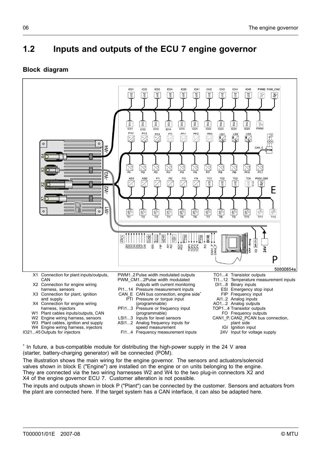
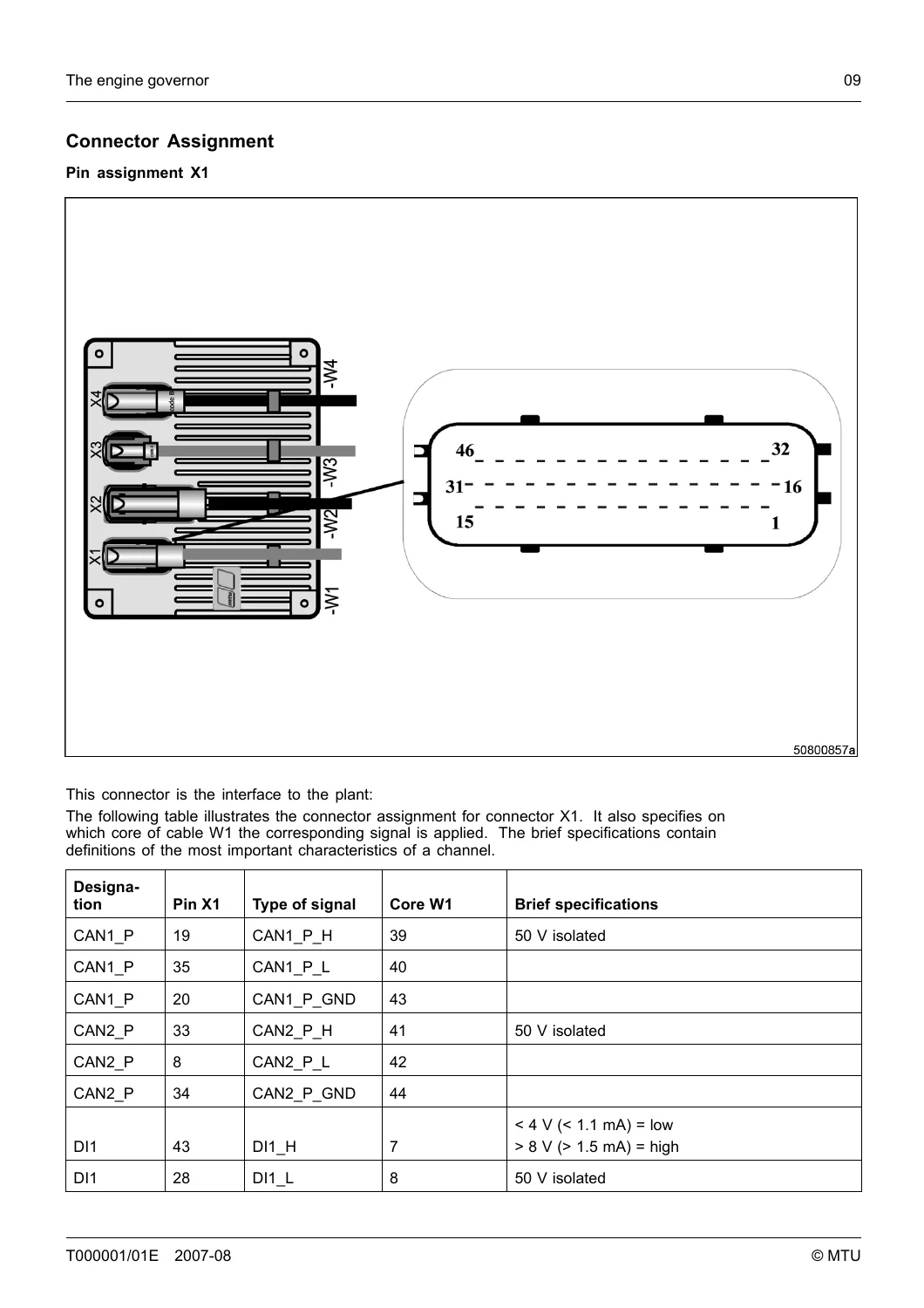
- 1.2 Inputs and Outputs (Block diagram, pin assignments for X1, X2, X3, X4)
- 1.3 Installation on Engine (Specifications, mechanical installation)
- 2. The Dialog System
- 2.1 The Dialog System DiaSys® (Design, connection options, software)
- 3. Parameter
- 3.1 Purpose and structure (Definitions, dongle access levels, ZKP number structure, number ranges)
- 4. Functions of the Engine Governor
- 4.1 Start Sequence (Internal starting sequence, settings, prelubrication, starter release, idle speed, manual turning)
- 4.2 Functions of the Engine Governor (Idle-max-speed governor, Common Rail injection, speed droop, power limitations, turbocharger, cylinder cutout, overspeed)
- 4.3 Test Functions (Bedia level sensors, binary outputs, overspeed test, integrated test system DILA)
- 4.4 Specified Speed Formation (Functional description, selection of setpoint source, Up/Down button, speed limits, sensor defect, default value mode, speed increase, speed droop, ramps)
- 5. Configurations of the Function Areas
- 5.1 Editing the Input and Output Setting (Transistor outputs, analog outputs, binary outputs, channel assignment)
- 5.2 1D Parameters (Definitions, sensor types, ECU channel numbers, extensive parameter table)
- 5.3 2D Parameters (Definitions, curve table)
- 5.4 3D Parameters (Definitions, characteristics map table)
- 5.5 Alarm Parameters (Setting options, standard settings for Genset and C&I applications)
- 5.6 Setting the Oil Pressure Differential Measurement (Analog sensors vs. pressure switch)
- 5.7 Monitoring and Protection Module (Structure, warning, limitation, reduction, stop functions)
- 5.8 Index
This comprehensive training document is essential for understanding the full capability of the MTU ECU-7 system. It enables technicians to perform advanced diagnostics, configure parameters for specific applications, and troubleshoot the electronic control system using the DiaSys® dialog system. The manual covers the complete parameter structure, from 1D and 2D parameters to complex 3D maps, allowing for fine-tuning of engine behavior and integration with marine, rail, or genset plants.
Why This Manual Matters
With over 4000 configurable parameters, the ECU-7 is a powerful but complex system. This manual is the key to unlocking its potential, providing the knowledge needed to adapt the governor to any application, set up speed control loops, configure alarms and protection modules, and ensure safe and efficient engine operation. Whether you are an OEM integrating the engine into a new plant or a service technician maintaining existing installations, this document provides the official MTU guidance you need.
Instant PDF Delivery
Upon completion of your purchase, you will receive an immediate download link for the PDF file. No shipping costs, no waiting. The file is fully printable and can be viewed on any device that supports PDFs, making it a convenient reference for your workshop or engineering office.




Reviews
There are no reviews yet.