
Isuzu F-Series Body Builders Guide 2011 PDF – Cab Chassis Rear Body Mounting Manual
Original price was: $34.95.$20.95Current price is: $20.95.
The Isuzu F-Series Body Builders Guide 2011 is the complete reference for mounting rear bodies and sub frames on F-Series cab chassis built for Australia. Covers all F-Series models, model identification, weight distribution, PTO and engine control, electrical add-ons, spring data, cab chassis and chassis frame drawings.
Description
Isuzu F-Series Body Builders Guide 2011 – Rear Body Mounting Reference for Australian F-Series Cab Chassis
The Isuzu F-Series Body Builders Guide 2011 is the reference document issued to body builders who carry out the final stage of vehicle manufacture by mounting rear bodies on Isuzu F-Series cab chassis supplied for the Commonwealth of Australia. It is the guide that sits between the incomplete cab chassis and a finished working truck, and it sets out how the chassis, frame, brakes, electrical system, PTO and suspension should be treated when a tipper, tray, van, crane body, service body or mixer is fitted.
This Isuzu F-Series body builders guide is structured around the actual work body builders perform: identifying the chassis from its ID plate and VIN, reading the principal specifications, designing and fitting a sub frame, avoiding prohibited modifications, maintaining clearances, and preserving the safety and warranty of the completed vehicle. It carries the model-by-model weight data, the spring and frame drawings, the PTO and governor information, and the piping and electrical diagrams needed to finish the job correctly.
File Details
- Manual type: Body builders guide / rear body mounting reference
- Brand: Isuzu
- Series: F-Series (2011 model year)
- Market: Commonwealth of Australia
- Language: English
- File format: PDF
- Page count: 383 pages
- Publication date: September 2010
- Issued by: Isuzu Motors Japan Limited
Chapters Covered in the Isuzu F-Series Body Builders Guide
- Introduction and identifying a cab chassis
- ID plate and ID code components
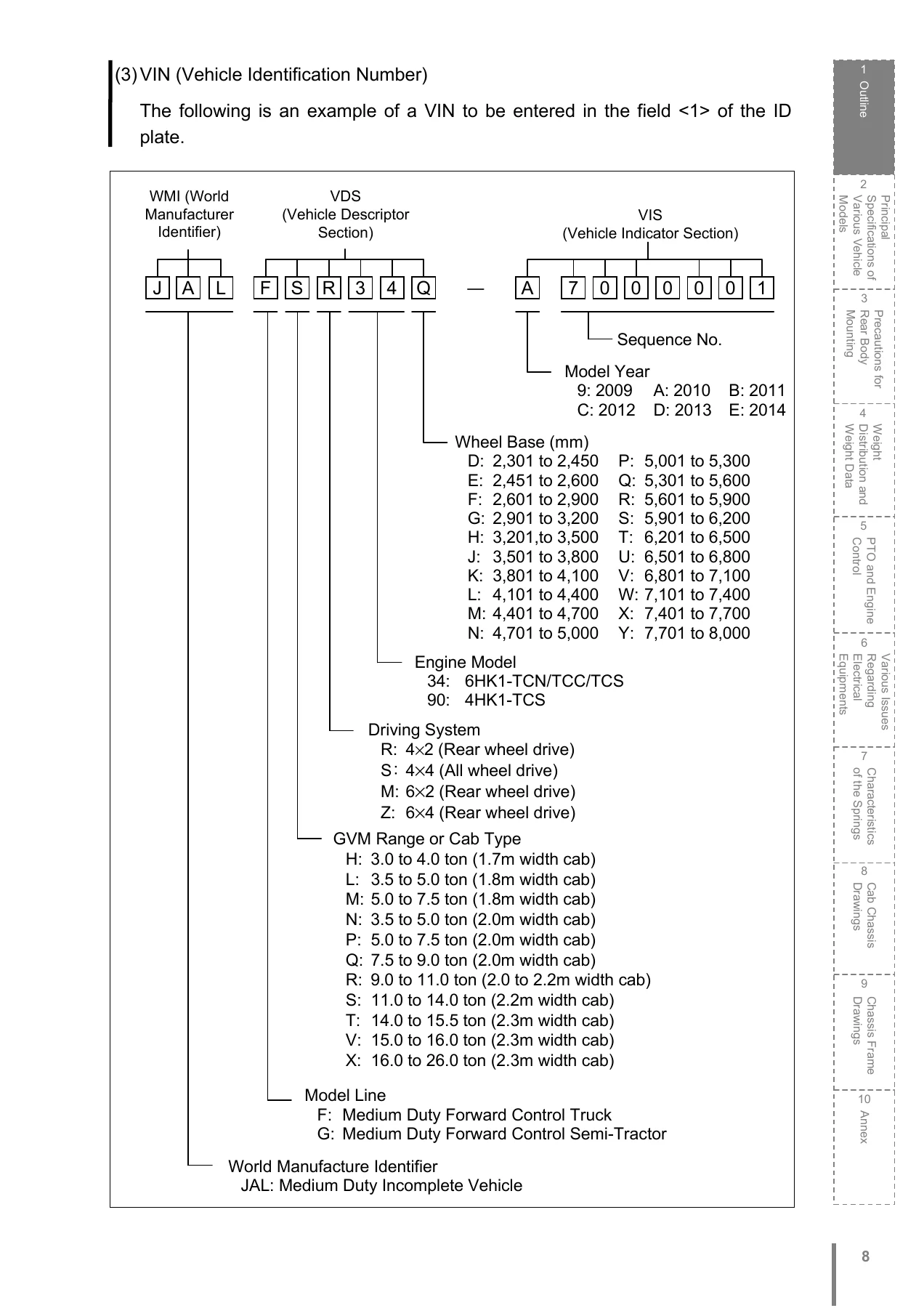
- VIN (Vehicle Identification Number) structure
- Location for carving vehicle number and engine model number
- Vehicle model code chart
- Principal specifications of the cab chassis for Australia
- General precautions
- Prohibited modification and maintainability
- Clearance between chassis equipment and rear body
- SRS airbag precautions
- Exhaust system precautions and heat clearance
- Outside rear view mirrors and rear body width
- Painting a disc wheel
- Mounting a rear body on air suspension chassis
- Adjusting air suspension chassis height
- Precautions for mounting a rear body
- Fixing bolts and areas from which bolts are kept away
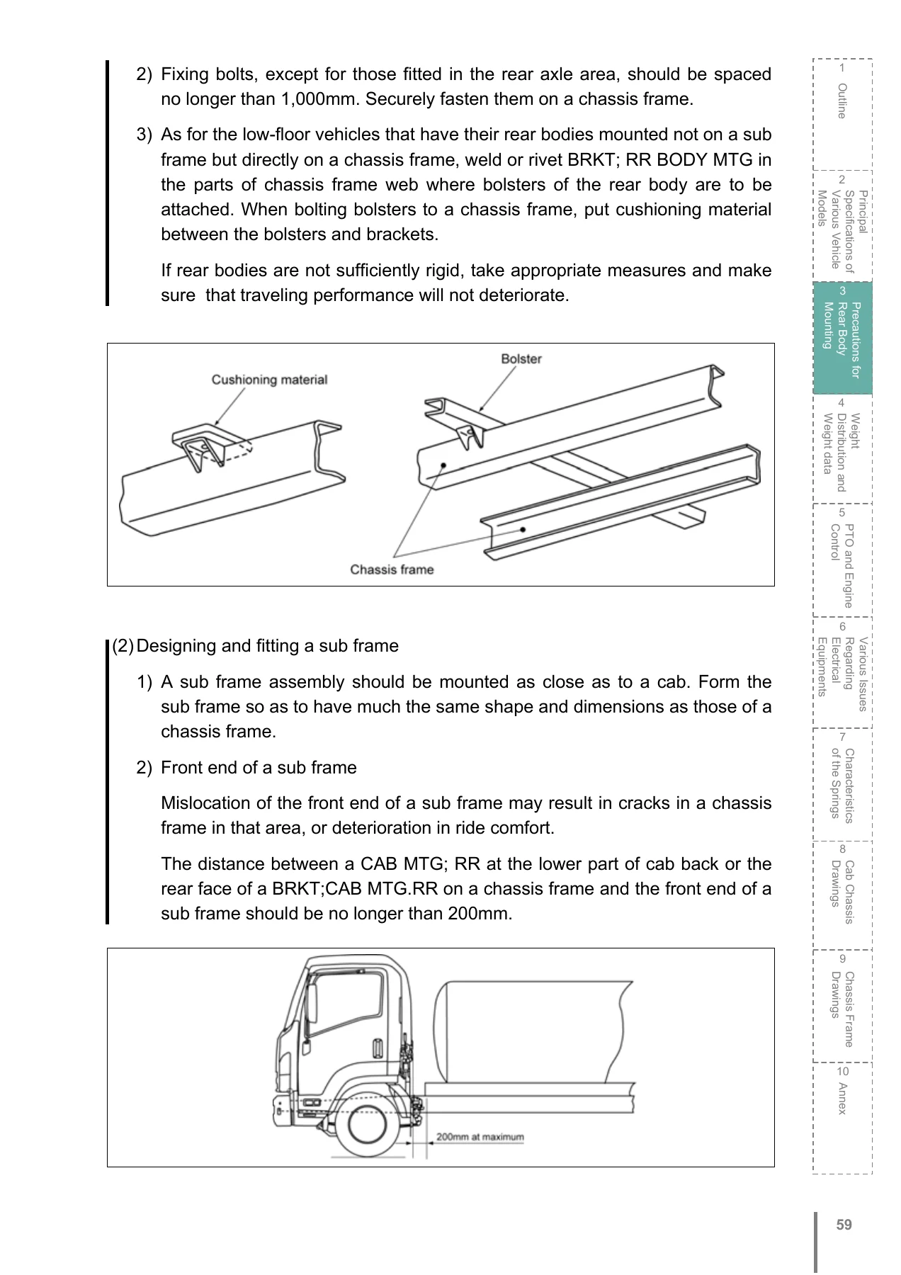
- Designing and fitting a sub frame
- Fastening U-bolts and double-ended brackets
- Fender precautions and rubber mud guard fitting
- Precautions for modification of a chassis frame
- Load on chassis frame side members
- Drilling or welding a chassis frame
- Reinforcing a chassis frame side member
- Modifying rear overhang
- Rivet plate
- Precautions for modification of chassis components
- Modifying an exhaust system
- Modifying a fueling system
- Precautions for installation of AMT
- General precautions for brake-related components
- Hill Start Aid (HSA)
- ABS and ASR
- Modifying a brake pipe or clutch pipe
- Hydraulic and air steel pipes
- Nylon air tubes and push-in connectors
- Paint-free portions of air drier and brake chamber
- Precautions for cab modification and cab painting
- Weight distribution and weight data
- Weight data tables
- Weight distribution calculation
- Front axle load rate
- Allowable load on axles and tires
- PTO and engine control
- PTO variation, transmission side PTO, flywheel PTO, transmission rear PTO
- PTO control and external engine control
- AMT: Automated Manual Transmission
- Governor characteristics curves
- Various issues regarding electrical equipment
- Working voltage and AC generator output characteristics
- Precautions for modification of electrical components
- Electric wiring, fuses and relays
- How to add power sources
- Adjusting the position of lamps
- Circuit diagrams
- Characteristics of the springs and spring specifications
- Formulas for calculating chassis frame top surface height
- Margin for movement of rear axle and tires
- Cab chassis drawings and chassis frame drawings
- Annex: piping diagrams and location of various components
What This Body Builders Guide Gives the Workshop
Mounting a rear body is not simply a matter of bolting a tray to a frame. The Isuzu F-Series Body Builders Guide exists because every F-Series chassis is designed with a particular load distribution and a particular set of legal obligations under the Australian Design Rules. Getting the sub frame shape, the U-bolt positions and the bolt spacing wrong can crack a chassis rail, void a warranty or fail an inspection. This manual explains where bolts may and may not go, how far a sub frame front end should sit from the cab mount, how to contour a sub frame over a bending frame, and how to avoid stress concentration in the section modulus.
It also spells out the modifications that must be avoided outright. The air inlet system, diesel fuel injection controls, engine assembly and exhaust emission control system, exhaust system, fuel system, engine cooling system, turbocharger controls, brake and brake control system, steering system, transmission and final gear, front and rear axles and disc wheel are all listed as areas where modification should be avoided for compliance and safety. Where modification cannot be avoided, the guide provides the permitted method.
For electrical work, the guide covers the working voltage and output characteristics of the AC generators, the location of the fuse box and relay box, the fuse ratings and their connected equipment, and how to add power sources for marker lamps, flasher lamps, stop lamps and back-up lamps. It explains how to splice wires, use waterproof connectors, route harnesses, protect against heat, and connect a large-load equipment to the positive battery terminal. The full circuit diagram list covers headlamps, tail and stop lamps, tachograph, meter, heater ventilation aircon, computer area network, immobiliser, wiper and washer, power window and door lock, retractable mirrors, supplemental restraint system, engine control module, transmission control module, ABS and ASR, air suspension, Hill Start Aid, PTO and power distribution.
The PTO chapter covers the side PTO, flywheel PTO and transmission rear PTO, the PTO switch, external engine control, the external engine control lever, PTO control modes, AMT precautions, and the engine and PTO output characteristics curves for the 4HK1-TCS and 6HK1-TCN/TCC engines. This is the material a body builder needs to safely run a tipper pump, crane, compactor or refrigeration unit from the chassis.
Covered Models and Engines
The guide covers the 2011MY FH F-Series for Australia, including the FRR 500, FRR 600, FSR 700/850, FSD 700/850, FTR 900, FVR 1000, FVD 1000, FVM 1400, FVU 1400, FVZ 1400, FVY 1400, FSS 550 4×4 and FTS 800 4×4 model families. Engine coverage is the 4HK1-TCS, 6HK1-TCN, 6HK1-TCC and 6HK1-TCS, all Euro 5 compliant.
Why This Manual Matters
This Isuzu F-Series body builders guide is the difference between a body that works with the chassis and one that fights it. It gives the correct bolt spacing, the correct clearances to exhaust and brake components, the correct weight distribution calculation, and the correct spring and frame data for each wheelbase. Used properly, it keeps the completed vehicle inside its gross axle weight ratings, protects the chassis frame from cracking, and keeps the truck compliant with the ADR requirements that apply to the completed body.
IMAGES PREVIEW
Instant PDF Delivery
The Isuzu F-Series Body Builders Guide 2011 is delivered as an instant PDF download after payment. There is no shipping and no waiting. The file can be opened on any device, searched on screen, and printed for use in the workshop or the body building bay. Keep it beside the chassis while the sub frame is being set out and while the electrical and PTO work is being completed.
Reviews
There are no reviews yet.