
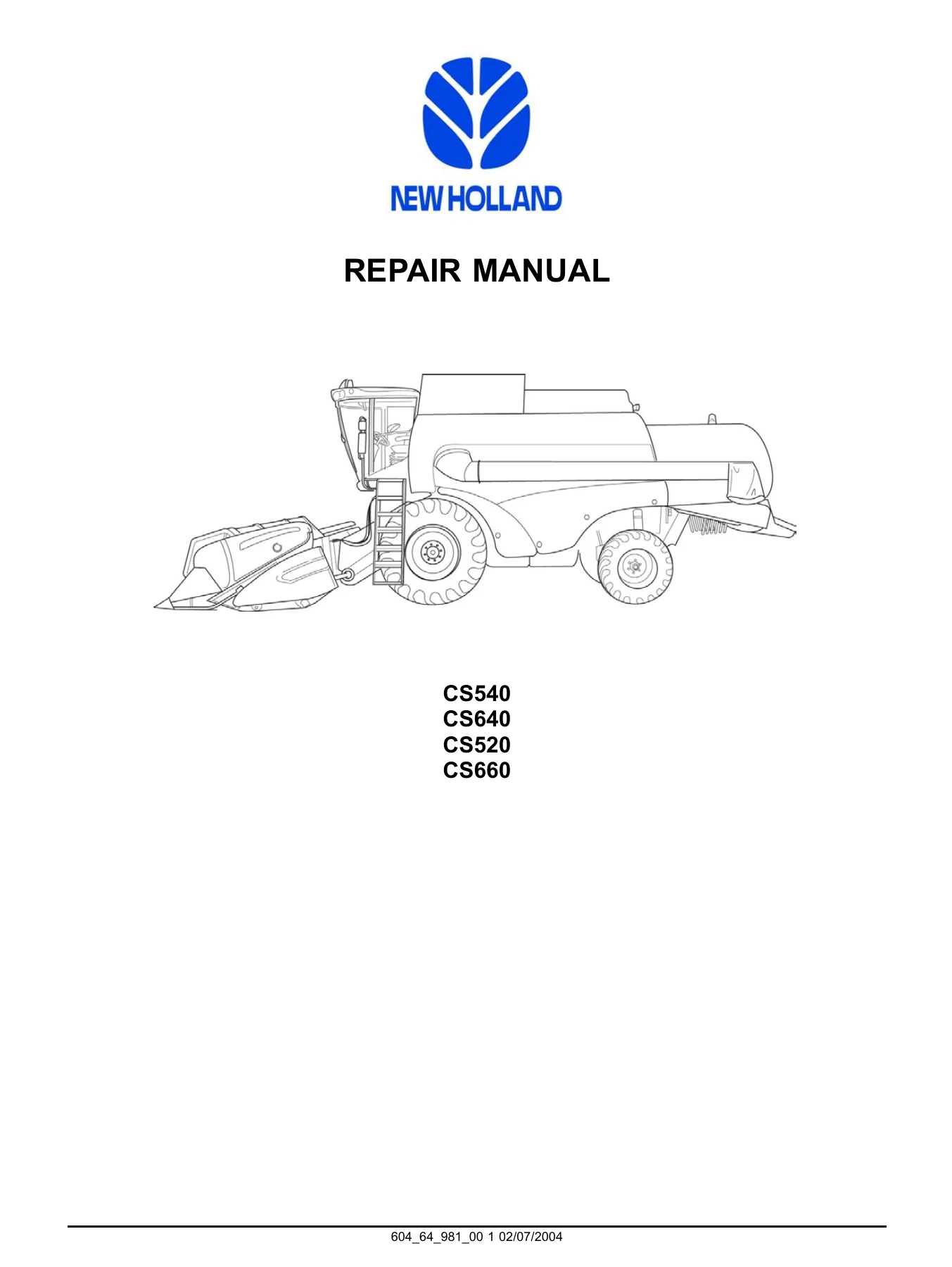
New Holland CS520 CS540 CS640 CS660 Combine Harvester Repair Manual 2004 PDF
Original price was: $39.95.$24.95Current price is: $24.95.
Complete 2004 New Holland repair manual for CS520, CS540, CS640 and CS660 combines. Over 2,000 pages of engine, hydraulic, electrical, transmission, brake, cab and crop-processing service data under document 604_64_981_00.
Description
New Holland CS520 CS540 CS640 CS660 Combine Harvester Repair Manual 2004
The New Holland CS520 CS540 CS640 CS660 Combine Harvester Repair Manual 2004 is the full workshop documentation set issued for these four CS-series machines under document number 604_64_981_00 and dated 02/07/2004. Across roughly two thousand pages it covers the hydraulic, pneumatic, electrical, electronic, engine, fuel, cooling, lubrication, starting, transmission, axle, steering, brake, cab, lifting, levelling and crop-processing systems fitted to the CS520, CS540, CS640 and CS660. Every chapter is organised into four information types: technical data (specifications), functional data (how the system works), diagnostic data (fault codes and troubleshooting) and service data (remove, disassemble, assemble, install, adjust).
File Details
- Manual type: Repair Manual (workshop service documentation)
- Brand: New Holland
- Models covered: CS520, CS540, CS640, CS660 combine harvesters
- Document number: 604_64_981_00
- Publication date: 02/07/2004
- Language: English
- File format: PDF
- Page count: approximately 2,088 pages
Chapters Covered
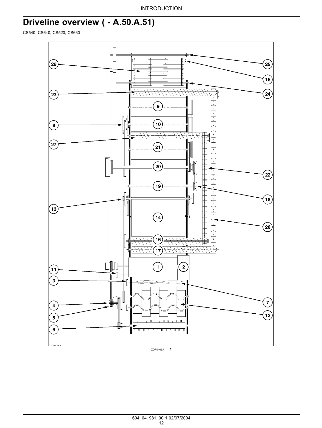
- Introduction — foreword, safety rules, driveline overview, basic instructions, torque values, conversion factors, product identification
- Distribution Systems (A) — primary hydraulic power system, pneumatic system, electrical power system, lighting system, electronic system
- Power Production (B) — engine, fuel and injection system, engine coolant system, lubrication system, starting system
- Power Train (C) — mechanical transmission, hydrostatic transmission, primary process drive
- Travelling (D) — front axle and final drive, rear axle, hydrostatic 2WD-4WD system, hydraulic steering, mechanical steering, hydraulic service brake, mechanical parking brake
- Body and Structure (E) — user controls and seat, user platform, heating system, air-conditioning system, combined heating/ventilation/air-conditioning, safety and security accessories
- Tool Positioning (G) — lifting, levelling
- Crop Processing (K) — header feeding, feeder housing, reel feeding, conventional threshing, beating, rotary separator, straw walker, primary cleaning, tailings return system, grain storing, grain unloading, straw chopper, reversing system
That outline is what makes this New Holland CS520 CS540 CS640 CS660 repair manual genuinely usable in a workshop. It is not a general combine book — the specifications, hydraulic schematics, wiring diagrams and diagnostic tables belong to these four CS models specifically. Each chapter opens with its own contents and index, so a technician can move from a fault code straight to the correct electrical schematic or troubleshooting table without wading through the rest of the manual.
Engine and Powertrain Coverage
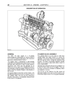
The Power Production section documents the CNH 7.5 litre six-cylinder turbocharged engine fitted to the CS range. Engine overhaul procedures cover the cylinder head, valve drive and camshaft, timing gears, crankshaft, connecting rods and pistons, flywheel, cylinder block rebore, rear cover and front and rear crankshaft seals. Full general specifications are given for the crankshaft journals, connecting rod and piston clearances, cylinder head and valve seat dimensions, camshaft bearing clearances and valve lash. A dedicated compression test procedure is included, along with engine troubleshooting charts for low power, excessive smoke, knocking, overheating, low oil pressure and excessive oil consumption.
Fuel and injection coverage describes the mechanically governed Bosch P7100 inline pump, the aneroid assembly, the overflow valve, the high-pressure pumping elements and delivery valves, and the fuel injector nozzle. Service procedures walk through injection pump removal and install, timing checks with the crank and pump timing pins, low idle adjustment, injector disassembly, cleaning, assembly, testing and installation. The fuel shut-off solenoid is covered with electrical feed checks and linkage adjustment. Lubrication and coolant chapters give the oil pump overhaul, oil pan, oil pressure regulator, water pump, thermostats and a full set of torque values. The starting system section includes logical diagrams for starting and engine kill-stop circuits plus starter motor, start relay, start switch and cold start control tests.
Electrical, Hydraulic and Electronic Systems
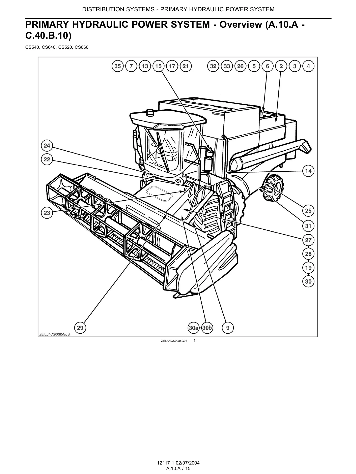
Distribution Systems is the largest single block of the manual. The primary hydraulic power system chapter covers the stack valve, relief valve, hydraulic triple pump, oil filter, breather and reservoir, with full hydraulic schematics, symbol legends, component localisation photographs and torque tables for union nuts, ferrules and metric fittings. The pneumatic system chapter documents the air compressor, pressure relief valve, air reservoir, command valves, sensing pressure switch and system schematics, including the change between series 1320–1368 and series 1376 onwards.
The electrical power system chapter is extremely detailed. It runs from frame 01 through frame 24 with in-line harness connectors, A-post module, CCM module, fuse printed circuits, multi-function handle, lighting printed circuits, relay and fuse identification, battery and alternator testing, sensor testing and a complete electrical symbol and standard reference. The electronic system chapter explains the CAN data bus, control box removal and installation, fault code index (E101 to E644) and audio system testing. The lighting system chapter provides testing procedures for headlights, turn and hazard lights, brake lights, beacons, front, rear, centre, inner, middle and outer work lights and the unloading tube light.
Transmission, Axles, Steering and Brakes
Power Train covers the mechanical three-speed traction gearbox in depth. Input shaft, drive shaft and differential shaft are each documented with exploded views, sectional views, removal, disassembly, assembly and installation procedures, plus end-float measurement and shim adjustment. The differential, differential lock command, shifting disc system, selector shaft and cover are all covered. The hydrostatic transmission chapter documents the Sauer Danfoss Series 90 pump and motor, the hydrostatic schematic, control valve, relief valve, shuttle spool valve, filling procedure, start-up procedure and full pressure test values for charge pressure, servo pressure and high pressure.
Travelling covers the front axle 10/75 and 11/111 final drives with complete disassembly and assembly sequences, output shaft end-play setting and wheel stud replacement. The rear axle hub, hydrostatic 2WD-4WD system and the Equa-Trac II control valve are documented with cross sections and operating descriptions. Steering is covered in both hydraulic and mechanical form, including the Danfoss OSPC 160 ON steering valve overhaul and steering cylinder seal replacement. Service brake and parking brake chapters cover bleeding, master cylinder operation, brake disc and lining replacement and command adjustment.
Cab, Controls and Crop Processing
Body and Structure covers the user controls and seat, mirrors and mirror adjustment circuits, the wiper and washer system, cab door switch and interior light, and the heating, ventilation and air-conditioning systems. Air-conditioning coverage is particularly thorough: refrigerant R-134a handling, compressor and magnetic clutch, condenser, receiver/drier, high and low pressure switches, evacuating, charging by weight, leak checking and a large gauge-reading troubleshooting matrix.
Crop Processing documents the complete material flow. Header feeding, feeder housing, reel feeding, feed chain, slip clutch, feeder drive shaft, bottom shaft, cradle and the hydraulic reverser are all covered with exploded and sectional views. Threshing includes the drum, concave types (cereal, maize, rice), drum variator belt and discs, drum bearings and shaft, rasp bar replacement, concave pivot plate adjustment and anti-wrap shield adjustment. Separating covers the beater, rotary separator and straw walker with bearing and shaft service and straw walker bearing detailed dimensions. Cleaning covers the shoe drive system, upper shoe, fan shaft and housing, fan variator, grain pan, upper sieve levelling system and fan deflector adjustment. Storing and handling documents the clean grain cross auger, grain elevator and tank delivery auger. Unloading covers the unloading tube, unloading drive system and unloading tube cylinder. Residue handling covers the straw chopper speed and swath plate position sensors, and the reversing system chapter provides a logical diagram for the hydraulic and electrical header reverser.
IMAGES PREVIEW
Diagnostics, Fault Codes and Specifications
A large proportion of this manual is diagnostic. Sensor fault codes are given with short-to-ground, short-to-B+ and open-circuit tests for groundspeed, drum, fan, straw walker, returns elevator, straw chopper, rotary separator, swath plate position, reel speed, header height, header pressure, autofloat position, grain loss, inclinometer, self-levelling actuator potentiometer and many more. Command valve and switch faults are covered for header up/down slow and fast, lateral float, reel speed up/down, automatic header height, unloading tube engagement, threshing engagement and reversing mechanism. Each procedure lists the possible failure modes and the exact connector pins and circuit numbers to check.
Specification tables are spread through every chapter: engine torque values and general specifications, crankshaft and connecting rod dimensions, cylinder head and valve seat data, fuel system pressures and injector opening pressures, coolant and oil capacities, transmission ratios and maximum torque, hydrostatic pump and motor displacements and pressures, final drive ratios and oil capacity, brake disc diameters, and crop-processing adjustments for concave clearance, drum variator belt, straw walker bearing positions and fan deflector plates.
Who This Manual Is For
This New Holland CS520 CS540 CS640 CS660 repair manual suits independent repair shops, farm workshops and owner-operators who maintain their own CS-series combine. It is written at a professional technician level, so it assumes access to normal workshop tooling and, for some tasks, the New Holland special tools listed in each chapter. Because the coverage spans four models, some procedures are split by series — for example electrical schematics are separated for series 1260, 1320–1324, 1364–1372 and 1376 onwards — and the correct series must be matched to the machine before following a diagram. The material is presented as a repair and service reference, not as an operator manual, and operating instructions for the combine itself are not included.
What This Manual Lets You Do
With this manual on hand a technician can diagnose a CAN network fault, identify which relay or fuse protects a circuit, set drum and fan variator belts, rebuild a final drive, overhaul the injection pump, adjust concave clearance, replace straw walker bearings, bleed the service brakes, recharge the air-conditioning system and trace a hydraulic load-sensing problem through the stack valve. Torque values, clearances, adjustment dimensions and troubleshooting charts are given at the point of use rather than in a separate appendix, which means the correct specification is available while the job is being carried out.
Correct procedures and the right specification matter on a machine of this size. An incorrectly shimmed final drive, a fan variator belt tensioned to the wrong setting or a load-sensing valve adjusted outside its 207 bar limit can turn a routine repair into a major failure. Working from the published figures rather than guesswork is the difference between a repair that lasts the season and one that does not.
Instant PDF Delivery
The manual is delivered as an instant PDF download after payment — no shipping, no waiting for a printed book. It can be opened on a workshop laptop, tablet or phone, and any page can be printed and taken to the machine. Because the file is a single PDF, sections can be searched and cross-referenced quickly during a repair, which is far more practical than flipping through a bound volume with oily hands. Whether the job is a routine service, an electrical fault on the A-post module or a full engine overhaul on a CS640, this New Holland CS520 CS540 CS640 CS660 Combine Harvester Repair Manual 2004 gives the specifications, diagrams and step-by-step procedures needed to get it done correctly.
Reviews
There are no reviews yet.