
★ TRUSTED BY 321,897+ PROFESSIONALS WORLDWIDE
🏒
Trusted Business
Verified & Licensed
πŸ›‘οΈ
Virus Free Files
100% Safe Downloads
πŸ”’
Secure Payment
SSL Protected
⚑
Instant Delivery
Available Immediately
Sale!

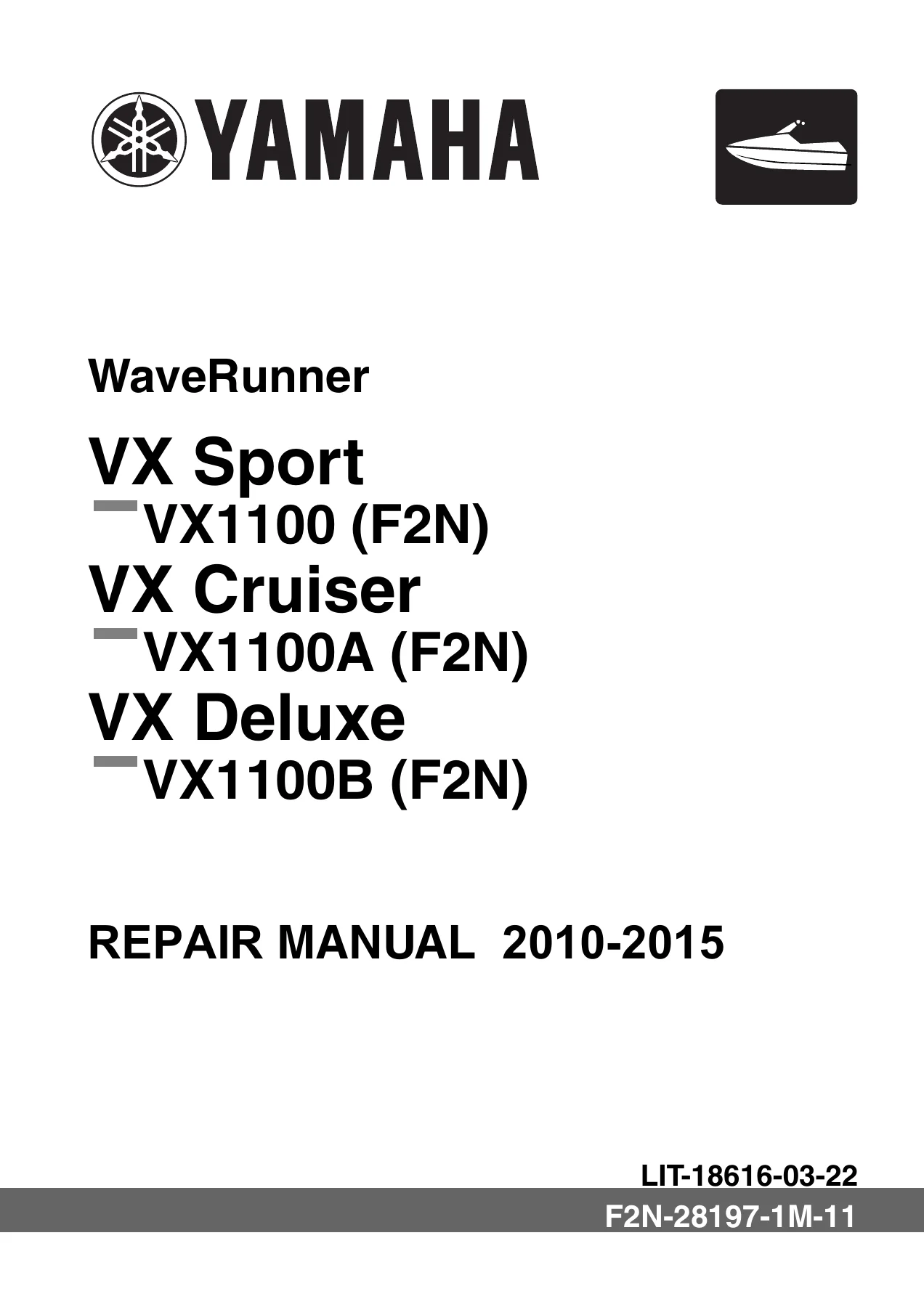
2010-2015 Yamaha WaveRunner VX Sport, VX Cruiser, VX Deluxe VX1100 Repair Manual

Original price was: $34.95.Current price is: $19.95.

Complete Yamaha repair manual for the 2010-2015 WaveRunner VX Sport, VX Cruiser, and VX Deluxe (VX1100 / F2N / 6BU). Covers the full 1052 cc four-stroke engine, jet pump, electrical system, hull, and troubleshooting with exploded views, torque specs, and step-by-step procedures.

⚑
Instant PDF Download
Available immediately
πŸ’Ύ
Save to Your Device
Download & keep forever
πŸ›‘οΈ
Antivirus Scanned
100% virus-free
🌍
Trusted Worldwide
175,000+ customers

Description

2010-2015 Yamaha WaveRunner VX Sport, VX Cruiser, VX Deluxe VX1100 Repair Manual

This complete Yamaha repair manual covers the WaveRunner VX Sport (VX1100), VX Cruiser (VX1100A), and VX Deluxe (VX1100B) personal watercraft built on the F2N hull and 6BU engine platform from 2010 through 2015. Issued by Yamaha Motor Corporation, U.S.A. under document number F2N-28197-1M-11, it is the same service reference prepared for Yamaha dealers and their trained mechanics. Every major system is documented in detail β€” from the 1052 cc four-stroke engine and its dry-sump lubrication circuit to the axial-flow jet pump, the electronic throttle valve system, the multifunction meter, and the hull and deck assemblies. If you own a VX1100 and intend to do your own maintenance or repairs, this manual tells you how the machine is actually built and how to take it apart without breaking it.

File Details

  • Manual type: Repair and service manual
  • Brand: Yamaha
  • Models covered: WaveRunner VX Sport VX1100 (F2N), VX Cruiser VX1100A (F2N), VX Deluxe VX1100B (F2N)
  • Model years: 2010–2015
  • Engine: 6BU, 4-stroke, L4, DOHC, 1052 cc
  • Language: English
  • Page count: 348
  • File format: PDF
  • Document number: F2N-28197-1M-11 (LIT-18616-03-22)
  • Edition: 1st Edition, January 2010

Chapters Covered

  • General Information β€” Safety while working, how to use this manual, abbreviations, model features, identification numbers, technical tips and engine control system overview
  • Specification β€” Model data, dimensions and weight, performance, power unit, drive unit, fuel and oil requirements, battery, fuel system technical data, power unit technical data, jet pump unit technical data, electrical technical data, specified tightening torques, general tightening torques, lubrication system, cooling system, cable and hose routing
  • Maintenance β€” Maintenance interval chart, steering system, throttle lever free play, shift cable, fuel system checks, spark plug and compression checks, valve clearance, engine oil and filter, air filter, trolling speed, impeller and jet pump checks, battery, bilge strainer, drain plug, lubrication points
  • Fuel System β€” Fuel pump module, fuel sender, fuel rail and injectors, fuel hose assembly, air filter case and throttle body assy., fuel tank, check valve, fuel filler neck, water separator
  • Power Unit β€” Engine unit and coupling cover, engine mounts, wiring harness assy. and starter motor, intake manifold, muffler, exhaust manifold, cooling water hose, oil tank assy., oil pump assy., reduction drive gear case, cylinder head cover, camshaft, cylinder head, generator cover and flywheel magneto, timing chain, crankcase, connecting rod, and piston
  • Jet Pump Unit β€” Intake grate and ride plate, jet pump unit removal and installation, reverse gate, nozzle / impeller housing / impeller duct assy., impeller, drive shaft, transom plate and hoses, intermediate housing
  • Electrical System β€” Electrical components, fuse box, ECM and rectifier regulator, electrical analysis, ignition system, charging system, control system (oil pressure switch, thermoswitches, engine temperature sensor, sensor assy., TPS, APS, ETV relay, cam position sensor, slant detection switch, steering sensor, ECM, earth plate), fuel system, starting system, starter motor, remote control system (VX Cruiser and VX Deluxe), indication system (multifunction meter, speed sensor, warnings, buzzer)
  • Hull and Hood β€” Steering pad and handlebar cover, handlebar and handlebar switch assy., throttle lever assy., front hood, multifunction meter and engine hatch cover, steering master, steering cable and speed sensor lead, seat and handgrip, ventilation hose and water separator, exhaust system, deck and hull, rear section
  • Troubleshooting β€” YDIS introduction and operation, engine unit troubleshooting using the YDIS, diagnostic code table and checking steps, engine unit troubleshooting when no diagnostic code is detected
  • Appendix β€” Wiring diagram for VX Sport and for VX Cruiser / VX Deluxe, color code legend, connector legend

Taken as a whole, this 2010-2015 Yamaha WaveRunner VX1100 repair manual gives a technician the complete service picture of the F2N machine. It pairs the Yamaha dealer maintenance schedule with the teardown procedures that sit behind it, so a repair can be planned from start to finish β€” checking the oil pressure switch, replacing the timing chain, resealing the crankcase, rebuilding the jet pump, or simply setting valve clearance to the correct cold specification. Every chapter cross-references the others, so you can move between a component removal, its inspection limits, and the torque table without leaving the manual.

Model Coverage and Identification

The manual is written for three distinct 2010-2015 WaveRunner variants: the VX Sport (VX1100, F2N hull and 6BU engine), the VX Cruiser (VX1100A, F2N, 6BU), and the VX Deluxe (VX1100B, F2N, 6BU). Identification numbers are documented so you can confirm your machine matches the book before starting work. The primary I.D. number is stamped on a label inside the engine compartment and starts at F2N: 800101. The engine serial number is stamped on a label on the engine unit and starts at 6BU: 1000001. The jet pump unit serial number is on a label attached to the intermediate housing, and the Hull Identification Number (H.I.N.) is stamped on a plate on the boarding platform. Model-equipment differences between the three variants are also listed β€” shift lever and reverse gate, reboarding step, remote control transmitter and receiver, and beverage holder β€” so you know exactly which procedures apply to your specific VX1100.

Engine, Jet Pump, and Electrical Systems

The 6BU engine documented here is a 1052 cc, four-stroke, inline-four with DOHC, a 76 Γ— 58 mm bore and stroke, an 11.4:1 compression ratio, and a dry-sump lubrication system. The manual walks through the cylinder head, camshafts with their camshaft caps and sprockets, valve clearance adjustment and the valve pad selection table, the crankcase and connecting rod bearings with bearing color selection charts, piston ring end-gap and side-clearance checks, and crankshaft journal oil clearance measurement using Plastigauge. The intake side covers the intake manifold joints, throttle body assy., and the fuel rail with its four injectors and O-rings. On the exhaust side, exhaust pipe 1, exhaust pipe 2, the exhaust manifold, and the thermoswitch (exhaust) are all broken down with their torque sequences.

The jet pump unit chapter covers the intake grate and ride plate, the impeller housing, impeller duct assy., drive shaft, front and rear bearings, oil seals, and the intermediate housing with its driven coupling. Impeller-to-housing clearance limits and impeller housing inside diameter are specified. On the electrical side, this VX1100 repair manual goes far beyond a wiring diagram β€” it documents the ignition coils, pickup coil, stator coil and rectifier regulator, the full control system (oil pressure switch, both thermoswitches, engine temperature sensor, intake air pressure and temperature sensor assy., TPS, APS, ETV relay, cam position sensor, slant detection switch, steering sensor, and ECM), the starting system with starter relay and starter motor, the remote control system for the VX Cruiser and VX Deluxe, and the indication system with the multifunction meter, speed sensor, warning indicators, and buzzer. Wiring diagrams for both the VX Sport and the VX Cruiser / VX Deluxe are included at the back of the book, along with the full Yamaha color-code legend.

What This Repair Manual Enables You to Do

With this manual in hand you can carry out the complete Yamaha maintenance schedule on a 2010-2015 VX1100 β€” steering and throttle cable checks, shift cable adjustment on VX Cruiser and VX Deluxe, fuel system inspection, spark plug and compression tests, valve clearance measurement and adjustment, engine oil and filter changes, air filter service, trolling speed verification, impeller and water inlet strainer checks, jet thrust nozzle steering angle adjustment, battery service, and lubrication of every grease point. Beyond scheduled maintenance, it supports real repair work: removing the engine unit, resealing the crankcase, replacing the timing chain and tensioner, rebuilding the cylinder head with new valve guides and seals, replacing pistons and rings, renewing the reduction drive gear case bearings and oil seals, rebuilding the jet pump, replacing the intermediate drive shaft, and diagnosing electrical faults through the YDIS and the diagnostic code tables.

The value of using the correct procedures and specifications is not abstract. Torque values on the cylinder head, crankcase, and jet pump drive coupling are given in multi-stage sequences with angle figures where required. Service limits for valve clearance, camshaft journal oil clearance, cylinder bore, crankshaft runout, impeller-to-housing clearance, and intermediate drive shaft runout are all listed so a worn part can be identified and replaced before it takes something else with it. Getting these numbers wrong on a personal watercraft is expensive and sometimes dangerous β€” a mis-torqued cylinder head or a stretched timing chain does not fail politely.

Complete PDF Bookmark Tree

Complete Bookmarks

The complete bookmarks in the β€œ2010-2015 Yamaha WaveRunner VX Sport, VX Cruiser, VX Deluxe VX1100 Repair Manual” are as follows:

Contents
General informationp. 5
Safety while workingp. 6
Rotating partp. 6
Hot partp. 6
Electric shockp. 6
Impellerp. 6
Handling of gasolinep. 6
Ventilationp. 7
Self-protectionp. 7
Working with cranep. 7
Handling of heat gunp. 8
Part, lubricant, and sealantp. 8
Handling of sealantp. 8
Special service toolp. 8
Tightening torquep. 8
Non-reusable partp. 8
Disassembly and assemblyp. 9
How to use this manualp. 10
Manual formatp. 10
Abbreviationp. 11
Adhesive, lubricant, sealant, and thread locking agentp. 12
Symbolp. 12
Special service toolp. 13
Model featurep. 20
General featurep. 20
Identification numberp. 21
Deck and hullp. 22
Intermediate drive shaftp. 23
ECM and rectifier regulatorp. 24
Multifunction meter unitp. 25
Multifunction display warningp. 26
Yamaha Security System (VX Cruiser and VX Deluxe)p. 27
Technical tipsp. 28
Engine controlp. 28
Engine control systemp. 33
Specificationp. 36
Model datap. 38
Model codep. 38
Dimension and weightp. 38
Performancep. 38
Power unitp. 38
Drive unitp. 39
Fuel and oil requirementp. 39
Battery requirementp. 39
Fuel system technical datap. 40
Fuel systemp. 40
Power unit technical datap. 40
Power unitp. 40
Cylinder head assy.p. 40
Crank case assy.p. 42
Jet pump unit technical datap. 43
Jet pump unitp. 43
Electrical technical datap. 43
Ignition systemp. 43
Charging systemp. 44
Control systemp. 44
Fuel systemp. 46
Starting systemp. 46
Meter systemp. 47
Specified tightening torquep. 48
Fuel systemp. 48
Power unitp. 48
Jet pump unitp. 51
Electrical systemp. 51
Hull and hoodp. 51
General tightening torquep. 53
Lubrication systemp. 54
Cooling systemp. 55
Cable and hose routingp. 56
Starboard bow viewp. 56
Top viewp. 58
Port viewp. 60
Maintenancep. 63
Maintenance interval chartp. 64
Periodic servicep. 65
Steering systemp. 65
Steering master checkp. 65
Throttle lever free play checkp. 65
Throttle lever free play adjustmentp. 65
Shift cable check (VX Cruiser and VX Deluxe)p. 67
Shift cable adjustment (VX Cruiser and VX Deluxe)p. 67
Fuel systemp. 68
Fuel pump module checkp. 68
Fuel hose checkp. 68
Fuel rail checkp. 68
Fuel filler neck and hose checkp. 69
Fuel tank checkp. 69
Water separator checkp. 69
Power unitp. 69
Spark plug checkp. 69
Compression pressure measurementp. 70
Valve clearance measurementp. 71
Engine oil level checkp. 72
Engine oil changep. 73
Oil filter replacementp. 73
Air filter element checkp. 74
Trolling speed checkp. 74
Engine mount, stopper, and spacer checkp. 74
Nut and bolt checkp. 74
Jet pump unitp. 75
Impeller checkp. 75
Water inlet strainer checkp. 75
Jet thrust nozzle steering angle checkp. 75
Jet thrust nozzle steering angle adjustmentp. 75
Electricalp. 76
Battery checkp. 76
Hull and hoodp. 77
Bilge strainer checkp. 77
Drain plug checkp. 77
Lubrication pointsp. 78
Throttle valve lubricationp. 78
Throttle cable (handlebar end) lubricationp. 78
Throttle cable (APS end) and return spring lubricationp. 78
Nozzle pivot shaft and steering cable lubricationp. 78
Steering cable and steering cable joint lubricationp. 79
Shift lever assy., shift cable, and shift cable joint lubrication (VX Cruiser and VX Deluxe)p. 79
Intermediate housing lubricationp. 79
Fuel systemp. 81
Fuel pump module, fuel hose, and fuel railp. 82
Fuel pump module removalp. 84
Fuel sender removalp. 84
Fuel pump module checkp. 85
Fuel sender installationp. 85
Fuel rail and injector removalp. 85
Fuel hose disassemblyp. 86
Fuel rail checkp. 86
Fuel line checkp. 86
Fuel injector checkp. 87
Fuel hose assemblyp. 87
Fuel rail and injector installationp. 88
Fuel pump module installationp. 89
Fuel pressure measurementp. 90
Air filter case and throttle body assy.p. 91
Air filter case removalp. 93
Air filter element checkp. 94
Air filter case assy. checkp. 94
Air filter case installationp. 94
Throttle body assy. removalp. 96
Throttle body assy. checkp. 96
Throttle body assy. installationp. 97
Fuel tankp. 98
Fuel tank removalp. 100
Check valve checkp. 101
Fuel filler neck and hose checkp. 101
Fuel filler cap checkp. 101
Fuel tank checkp. 101
Fuel tank installationp. 102
Power unitp. 104
Engine unitp. 108
Engine unit and coupling coverp. 110
Engine mount and stopperp. 111
Engine unit removalp. 112
Engine mount, stopper, and spacer checkp. 115
Engine unit installationp. 115
Wiring harness assy. and starter motorp. 121
Wiring harness assy. and starter motor removalp. 123
Wiring harness assy. checkp. 124
Starter motor checkp. 124
Wiring harness assy. and starter motor installationp. 124
Intake assy.p. 127
Intake manifold removalp. 128
Intake manifold disassemblyp. 128
Intake manifold checkp. 128
Intake manifold joint checkp. 128
Intake manifold assemblyp. 128
Intake manifold installationp. 129
Mufflerp. 131
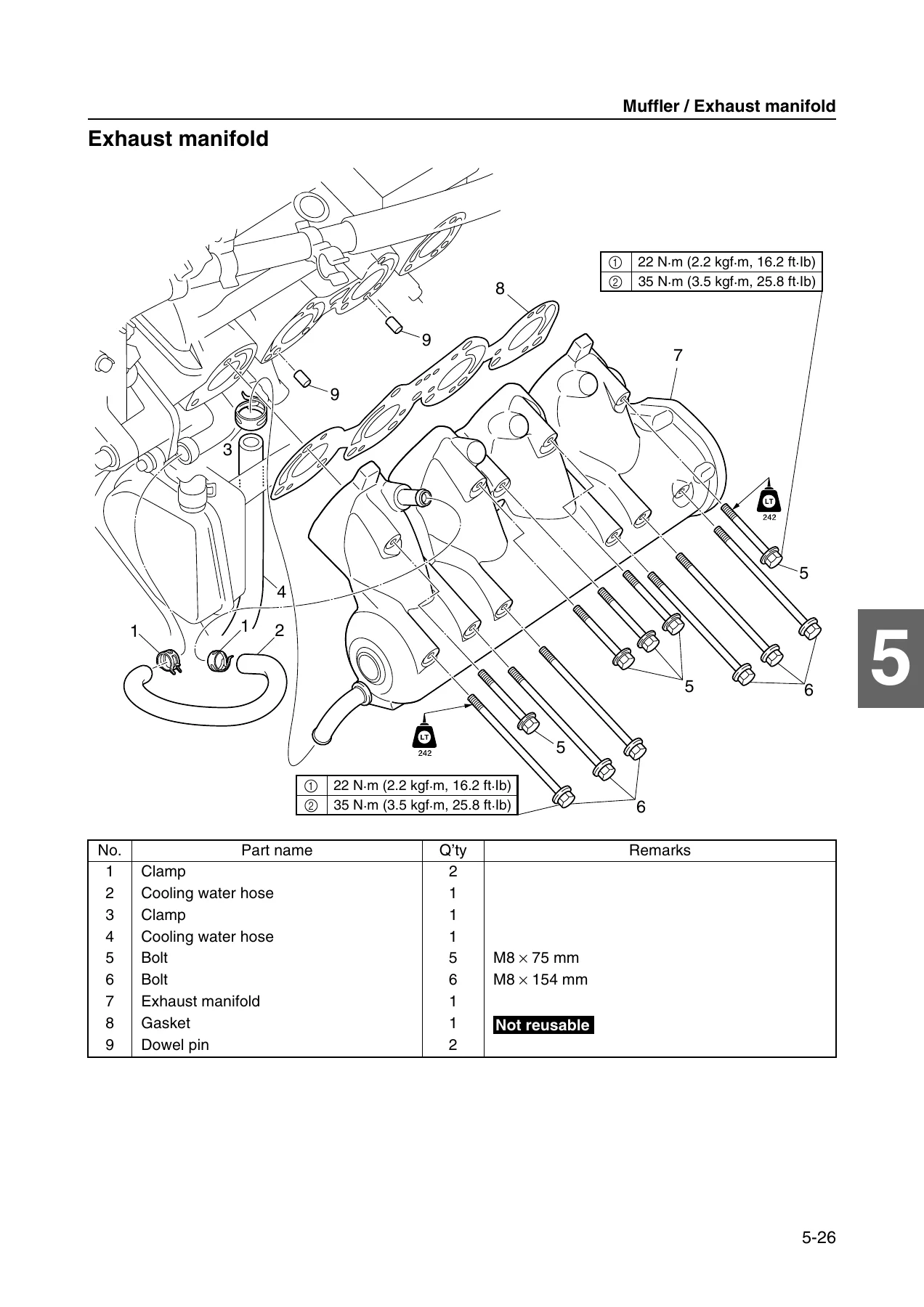
Exhaust manifoldp. 133
Exhaust pipe removalp. 134
Exhaust manifold removalp. 134
Exhaust pipe disassemblyp. 135
Exhaust pipe end and silencer checkp. 135
Exhaust pipe 1 and exhaust pipe 2 checkp. 135
Exhaust manifold checkp. 135
Exhaust joint checkp. 136
Thermoswitch (exhaust) checkp. 136
Exhaust pipe assemblyp. 136
Exhaust manifold installationp. 136
Exhaust pipe installationp. 137
Cooling water hosep. 139
Oil tank assy.p. 141
Oil tankp. 143
Oil tank assy. removalp. 145
Oil tank assy. checkp. 146
Oil tank disassemblyp. 146
Cooling water hose and joint checkp. 148
Oil separator and breather hose checkp. 148
Oil tank filler cap and O-ring checkp. 148
Oil tank and oil cooler cover checkp. 148
Oil strainer checkp. 149
Oil tank cover checkp. 149
Oil breather plate and baffle plate checkp. 149
Anode checkp. 149
Oil tank assemblyp. 149
Oil tank assy. installationp. 152
Oil pump assy.p. 154
Oil pump assy. removalp. 155
Oil pump assy. checkp. 155
Oil strainer checkp. 155
Oil pump assy. installationp. 155
Reduction drive gear case assy.p. 157
Reduction drive gear casep. 158
Reduction drive gear case assy. removalp. 159
Reduction drive gear case disassemblyp. 159
Reduction drive gear checkp. 161
Oil pump drive shaft checkp. 161
Drive shaft checkp. 161
Reduction drive gear case assemblyp. 161
Reduction drive gear case assy. installationp. 164
Cylinder head coverp. 165
Camshaftp. 166
Cylinder head cover removalp. 167
Cylinder head cover disassemblyp. 167
Camshaft removalp. 168
Camshaft sprocket removalp. 169
Camshaft checkp. 169
Camshaft journal oil clearance checkp. 170
Camshaft sprocket checkp. 171
Timing chain tensioner checkp. 172
Camshaft sprocket installationp. 172
Camshaft installationp. 172
Valve clearance adjustmentp. 175
Valve pad selection tablep. 177
Cylinder head cover assemblyp. 178
Cylinder head cover installationp. 178
Cylinder headp. 180
Valve and valve springp. 181
Cylinder head assy. removalp. 183
Cylinder head disassemblyp. 183
Cylinder head checkp. 184
Valve spring checkp. 184
Valve checkp. 185
Valve guide checkp. 186
Valve guide removalp. 186
Valve guide installationp. 186
Valve seat checkp. 187
Valve seat refacingp. 188
Cylinder head assemblyp. 190
Cylinder head installationp. 191
Generator cover assy. and flywheel magnetop. 193
Generator coverp. 194
Generator cover assy. removalp. 195
Flywheel magneto removalp. 195
Generator cover assy. disassemblyp. 196
Starter clutch checkp. 196
Starter gear checkp. 196
Starter clutch operation checkp. 196
Generator cover assy. assemblyp. 196
Flywheel magneto installationp. 197
Generator cover assy. installationp. 198
Timing chain and electrical partp. 199
Crankcase, connecting rod, and pistonp. 201
Timing chain and timing chain guide (intake side) removalp. 203
Electrical part and anode removalp. 203
Oil filter bolt removalp. 203
Stud bolts removalp. 203
Oil pan removalp. 203
Crankcase disassemblyp. 204
Connecting rod and piston removalp. 205
Timing chain checkp. 205
Anode checkp. 205
Crankcase checkp. 205
Piston checkp. 206
Piston ring checkp. 206
Piston pin checkp. 207
Connecting rod checkp. 207
Cylinder block checkp. 207
Crankshaft checkp. 208
Crankshaft pin oil clearance checkp. 208
Connecting rod bearing selectionp. 209
Crankshaft journal oil clearance checkp. 210
Crankshaft bearing selectionp. 212
Connecting rod and piston installationp. 213
Crankcase assemblyp. 215
Oil pan installationp. 217
Stud bolt installationp. 217
Oil filter bolt installationp. 217
Electrical part and anode installationp. 218
Timing chain and timing chain guide (intake side) installationp. 218
Jet pump unitp. 221
Intake grate and ride platep. 222
Jet pump unitp. 223
Jet pump unit removalp. 225
Jet pump unit installationp. 225
Reverse gatep. 227
Nozzle, impeller housing, and impeller duct assy.p. 228
Impeller, drive shaft, and impeller ductp. 229
Impeller duct assy. disassemblyp. 230
Impeller checkp. 231
Impeller housing checkp. 231
Drive shaft checkp. 231
Impeller duct assy. assemblyp. 231
Impeller duct, impeller housing and nozzle installationp. 233
Transom plate and hosesp. 235
Water hose checkp. 237
Hose joint checkp. 237
Bilge strainer checkp. 237
Transom plate installationp. 237
Intermediate housingp. 238
Intermediate housing assy. removalp. 239
Intermediate housing assy. disassemblyp. 239
Intermediate drive shaft checkp. 240
Driven coupling and intermediate housing checkp. 240
Intermediate housing assy. assemblyp. 240
Intermediate housing assy. installationp. 242
Electrical systemp. 244
Electrical componentsp. 246
Fuse boxp. 249
ECM and rectifier regulatorp. 251
Electrical analysisp. 252
Check using the YDISp. 252
To supply power to the ECM (VX Cruiser and VX Deluxe)p. 252
To supply power to the ECM (VX Sport)p. 253
To measure the peak voltagep. 253
Ignition systemp. 254
Ignition coilp. 254
Pickup coilp. 255
Charging systemp. 256
Stator coilp. 256
Rectifier regulatorp. 257
Control systemp. 259
Oil pressure switchp. 259
Thermoswitch (engine)p. 260
Thermoswitch (exhaust)p. 261
Engine temperature sensorp. 261
Sensor assy. (intake air pressure and intake air temperature)p. 262
Throttle position sensorp. 263
Accelerator position sensorp. 265
Electronic throttle valve relayp. 268
Cam position sensorp. 268
Slant detection switchp. 269
Steering sensorp. 270
ECMp. 271
Earth platep. 272
Fuel systemp. 272
Fuel injectorp. 272
Fuel pump modulep. 273
Starting systemp. 273
Fusep. 273
Left handlebar switch assy.p. 274
Main and fuel pump relayp. 274
Starter relayp. 275
Starter motorp. 277
Starter motor operationp. 278
Starter motor disassemblyp. 278
Armaturep. 278
Front and rear coverp. 279
Brush holderp. 280
Starter motor assemblyp. 280
Remote control system (VX Cruiser and VX Deluxe)p. 281
Remote control transmitterp. 281
Remote control receiverp. 283
Transmitter registrationp. 283
Indication systemp. 284
Multifunction meterp. 284
Speed sensorp. 285
Fuel level meter display and fuel level warning indicatorp. 285
Check engine warning indicatorp. 286
Diagnostic displayp. 286
Oil pressure warning indicatorp. 286
Engine overheat warning indicatorp. 287
Buzzerp. 287
Hull and hoodp. 290
Steering pad and handlebar coverp. 292
Handlebar and handlebar switch assy.p. 293
Left handlebar switch assy. and throttle lever assy.p. 294
Throttle cable removalp. 295
Handlebar checkp. 295
Left handlebar switch assy. checkp. 295
Handlebar assy. installationp. 295
Steering pad and handlebar cover installationp. 297
Front hoodp. 299
Service lid installationp. 301
Hinge assy. checkp. 301
Hood lock checkp. 301
Multifunction meter and engine hatch coverp. 302
Steering master assy.p. 304
Steering masterp. 305
Shift lever assy. checkp. 306
Bushing checkp. 306
Steering shaft checkp. 306
Steering arm assy. installationp. 306
Steering cable and speed sensor leadp. 307
Steering cable installation (steering master end)p. 309
Steering cable installation (jet pump end)p. 309
Shift cable installation (shift lever end) (VX Cruiser and VX Deluxe)p. 309
Seat and handgripp. 311
Ventilation hose and water separatorp. 312
Seat lock checkp. 314
Water separator assy. removalp. 314
Water separator checkp. 314
Water separator assy. installationp. 314
Cooling water pilot outlet installationp. 315
Ventilation hose installationp. 315
Exhaust systemp. 317
Exhaust system checkp. 319
Exhaust system installationp. 319
Deck and hullp. 321
Rear sectionp. 322
Drain plug checkp. 324
Spout installationp. 324
Reboarding step assy. installation (VX Cruiser)p. 324
Troubleshootingp. 325
YDISp. 326
Introductionp. 326
Operatingp. 329
Engine unit troubleshootingp. 330
Using the YDIS for engine unit troubleshootingp. 330
Engine unit troubleshooting (diagnostic code not detected)p. 337
Appendixp. 343
Wiring diagramp. 344
How to use the wiring diagramp. 344

Get Instant Access to the Yamaha VX1100 Repair Manual

IMAGES PREVIEW

2010-2015 Yamaha WaveRunner VX Sport, VX Cruiser, VX Deluxe VX1100 Repair Manual β€” PDF page 1 preview
2010-2015 Yamaha WaveRunner VX Sport, VX Cruiser, VX Deluxe VX1100 Repair Manual β€” PDF page 133 preview
2010-2015 Yamaha WaveRunner VX Sport, VX Cruiser, VX Deluxe VX1100 Repair Manual β€” PDF page 193 preview

This 2010-2015 Yamaha WaveRunner VX Sport, VX Cruiser, and VX Deluxe VX1100 repair manual is delivered as an instant PDF download. There is no shipping, no waiting for a physical book, and no risk of a missing or torn page. The file opens on any computer, tablet, or smartphone with a PDF reader, and you can print the sections you need for the garage bench and leave the rest on the device. Search, zoom, and jump straight to the chapter that matches the job in front of you. Whether you are servicing a VX Sport, diagnosing a VX Cruiser, or rebuilding a VX Deluxe jet pump, the procedures, specifications, and diagrams are all in one place.
Reviews

There are no reviews yet.

Be the first to review “2010-2015 Yamaha WaveRunner VX Sport, VX Cruiser, VX Deluxe VX1100 Repair Manual”

What Our Customers Say

β˜…β˜…β˜…β˜…β˜… Live reviews from customers
Loading customer reviews...
0
    0
    Your Cart
    Your cart is emptyReturn to Shop
    πŸ›’
    Recently Purchased
    πŸ•’ verified order