
MAN D0836 LF01 LF03 LF05 LFL02 LFL03 Repair Manual A13-A1 – 81.99198-6452 PDF Download
Original price was: $52.95.$34.95Current price is: $34.95.
Complete MAN repair manual A13-A1 for D 0836 LF01, LF03, LF05, LFL02 and LFL03 in-line diesel engines. Covers cooling, fuel, supercharging, cylinder head, valve timing, lubrication, crankshaft drive and engine housing with step-by-step procedures, torque values and special tools. Instant PDF download.
Description
MAN D 0836 In-Line Engine Repair Manual A 13-A1
This MAN D0836 LF01 LF03 LF05 LFL02 LFL03 repair manual is the complete workshop guide for the D 0836 series of in-line diesel engines. Published as Repair Manual A 13-A1 under document number 81.99198-6452, it covers every major engine system from cooling and fuel delivery through to crankshaft drive and engine housing. Whether you are a workshop technician, fleet mechanic or serious owner, this D 0836 engine repair manual gives you the procedures, torque values and special tool references needed to carry out repairs correctly.
File Details
- Manual Type: Repair Manual (Reparaturanleitung)
- Brand: MAN Nutzfahrzeuge AG
- Models Covered: D 0836 LF 01, D 0836 LF 03, D 0836 LF 05, D 0836 LFL 02, D 0836 LFL 03
- Document Number: 81.99198-6452
- Publication: Repair Manual A 13-A1
- Edition: 1st Edition
- Copy Deadline: 12.2003
- Language: English
- Page Count: 290
- File Format: PDF
Chapters Covered
- Introduction
- Cooling System
- Add-On Units
- Fuel System
- Supercharging
- Induction / Exhaust System
- Cylinder Head
- Valve Timing
- Engine Lubrication
- Crankshaft Drive
- Engine Housing
Introduction
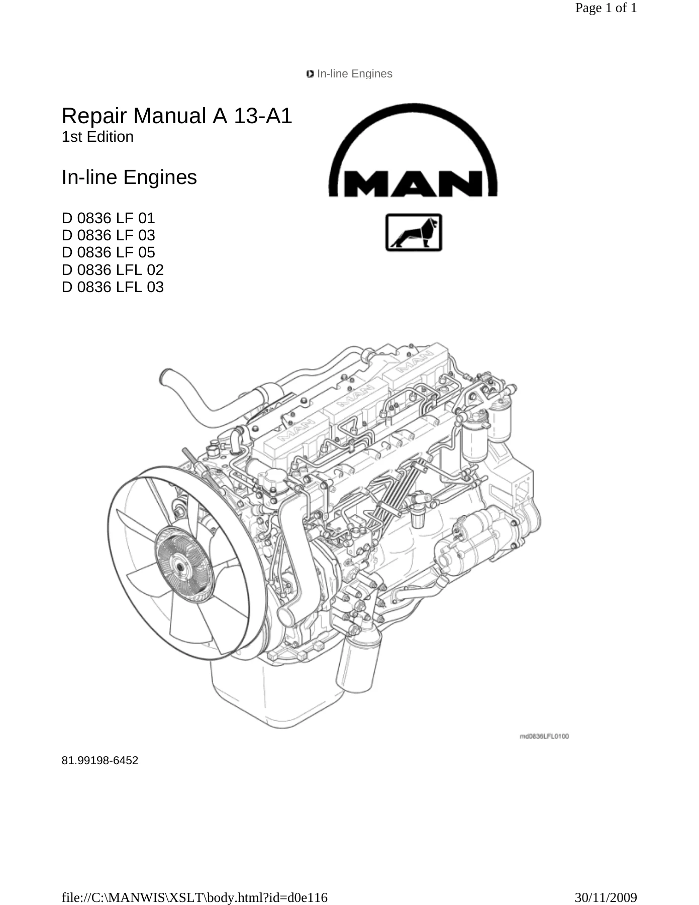
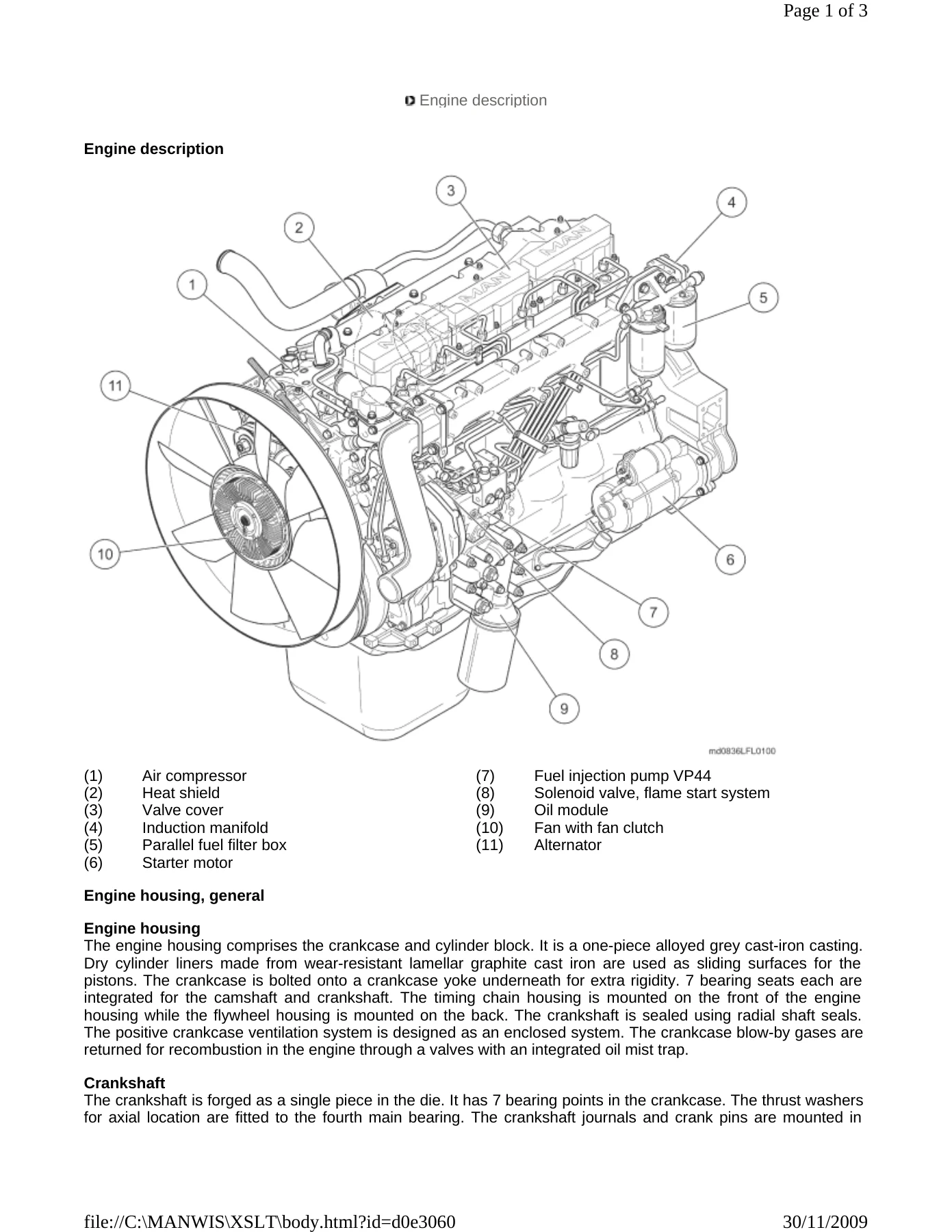
The introduction opens with comprehensive safety regulations covering general workshop practice, brake system work, engine operation, suspended loads, high-pressure lines, vehicle electrical systems, electric welding, plastic tubes, painting, cab tilting and air-conditioning. It also includes guidance on preventing damage and premature wear, limited liability for accessories and parts, handling brake pads, and regulations for avoiding injury and environmental contamination. The type plate and type designation section explains engine identification, reworking levels (NI/NII) for crankshaft bearings, main bearings, connecting rod bearings, pistons and cylinder liners, plus the engine number breakdown. Characteristic data tables list power, torque, bore, stroke, swept volume and firing sequence for each D 0836 variant. The engine description gives a detailed overview of the engine housing, crankshaft, connecting rods, pistons, camshaft, lubrication, cooling system, cylinder head, induction and exhaust systems, fuel system, engine brake system (EVB), starter motor, alternator, flame start system and air compressor.
Cooling System
Covers the fan (both coolant pump and vibration damper mounting configurations) with removal and installation procedures, fan clutch handling warnings, and torque values for mounting bolts and nuts. Coolant pipes are detailed with removal and installation of the coolant distributor pipe, coolant temperature sensors, hose ports and air compressor coolant lines. The thermostat and thermostat housing section covers both single and double thermostat equipment variants, including removal and installation of the cover, thermostat, housing and seals. The coolant pump chapter includes removal and installation, plus dismantling and assembling with bearing, slip ring seal, vane impeller and hub procedures, including special tools for pulling off the hub and pressing in seals.
Add-On Units
The air compressor and steering booster pump chapter covers removal and installation of both components, including support block, driver plate, O-rings and mounting bolt torque values. The alternator section details V-belt sheave removal using special spanners, cable connection disconnection, counterholding plate removal and installation with torque values. The starter motor chapter covers removal and installation with mounting nut and bolt torque values, plus a note on checking the flywheel ring gear before installation. The belt drive chapter covers V-belt slackening, removal and installation of the V-belt tensioner, V-belt tension checking using a tension tester, and V-belt tightening with specified tension values.
Fuel System
The injector nozzle chapter covers removal and installation, including needle travel sensor handling, pressure screw torque values, leakage oil line removal and installation, and injector nozzle checking procedures for opening pressure, leaks and spray jet. The fuel injection pump section details removal and installation, including engine crankshaft positioning, fuel pump removal, injection line removal and installation with special spanner, blocking device procedures, and start of pumping checking and setting. The low-pressure system chapter covers the fuel filter head, bleed screws, fuel filter heater, primary fuel filter, hand fuel pump and parallel fuel filter box with removal, installation and bleeding procedures. The flame start system chapter covers the flame glow plug and solenoid valve with removal and installation procedures.
Supercharging
Covers the turbocharger with removal and installation procedures, including charge air pipe, induction port, oil return line and oil pressure line removal and installation. Includes wastegate valve specifications, turbocharger filling with clean engine oil before first start, and torque values for mounting nuts and oil line bolts.
Induction / Exhaust System
The exhaust manifold chapter covers heat shield removal and installation, manifold removal and installation with seal positioning notes, and tightening in stages (preliminary and final torque plus angle). The induction manifold chapter covers removal and installation, charge air pressure sensor removal and installation, and mounting bolt torque values.
Cylinder Head
The rocker arm mechanism chapter covers dismantling and assembling with or without EVB, including circlip removal, rocker arm shaft removal, bearing block and rocker arm positioning, and assembly paste application. The cylinder head chapter covers removal and installation, cylinder head gasket replacement, distortion checking with a bevelled steel edge and feeler gauge, and the full tightening sequence with special tools including force multiplier spanner and angle measuring disc. Valve clearance checking and setting covers exhaust valve clearance, induction valve clearance and EVB piston play with feeler gauge procedures and locknut torque values.
Valve Timing
The camshaft and camshaft bearing chapter covers removal and installation of the camshaft, axial shim, tappets and camshaft bearings 1 through 7, including bearing removal and installation sequences, special tools for bearing extraction and installation, and camshaft guide tool usage. The timing gears chapter covers camshaft gear and crankshaft gear removal and installation, idler gear 1 and idler gear 2 removal and installation, timing mark alignment, and backlash specifications.
Engine Lubrication
The oil module chapter covers removal and installation of the oil module, oil cooler, oil pressure switch, screw-in port and temperature sensor for the flame start system. The oil sump chapter covers oil sump cover removal, oil sump removal and installation, oil suction pipe removal and installation, and oil excess pressure valve removal and installation. The oil pump chapter covers removal and installation, drive gear removal, end play and radial play checking, dismantling and assembling, and coupling sleeve installation. The oil injector nozzles chapter covers removal and installation with oil pressure valve torque values and alignment notes.
Crankshaft Drive
The vibration damper chapter covers removal and installation with engine barring gear usage and torque specifications. The flywheel chapter covers removal and installation, flywheel lateral run-out checking, flywheel ring gear removal and installation with heating temperature, clutch pilot bearing removal and installation, and flywheel bolt tightening using special tools. The piston and connecting rod chapter covers removal and installation, gudgeon pin removal and installation, piston ring removal and installation, ring gap checking, piston ring axial play checking, connecting rod bearing checking, piston standout checking, and connecting rod bolt tightening with angle torque. The crankshaft chapter covers removal and installation, crankshaft main bearing removal and installation, crankshaft end play checking, crankshaft journal measurement, and main bearing bolt tightening with special tools.
Engine Housing
The cylinder liner chapter covers removal and installation, cylinder liner protrusion checking, and liner height specifications. The flywheel housing chapter covers removal and installation, crankshaft oil seal removal and installation with special tools, and PTFE sealing ring handling precautions. The timing chain housing chapter covers removal and installation, timing chain housing cover removal and installation, gasket replacement, and crankshaft oil seal removal and installation. The crankcase yoke chapter covers removal and installation with sealing agent application and turbocharger oil return line fitting. The positive crankcase ventilation chapter covers removal and installation of the ventilation filter, tube and line with spring-loaded band-type clamp handling.
Why This MAN D 0836 Repair Manual Matters
Working on a MAN D 0836 engine without the correct procedures is a recipe for expensive mistakes. This manual gives you the exact torque values, tightening sequences, special tool references and clearance specifications that MAN specifies for the LF01, LF03, LF05, LFL02 and LFL03 variants. From routine maintenance like valve clearance adjustment and V-belt tensioning to major overhauls involving cylinder head removal, camshaft bearing replacement, piston and connecting rod work, or crankshaft removal, every procedure is documented with step-by-step instructions and accompanying illustrations.
The manual covers the VP44 fuel injection pump with start of pumping checking and setting, the flame start system for cold starting, the turbocharger with wastegate valve specifications, the engine brake system (EVB) with hydraulic piston operation, and the complete cooling circuit with thermostat and coolant pump servicing. Whether you are diagnosing a fuel delivery issue, rebuilding a cylinder head, replacing a crankshaft oil seal, or checking piston standout, this D 0836 engine repair manual has the technical depth you need.
IMAGES PREVIEW
Instant PDF Delivery — No Shipping, No Waiting
This MAN D0836 repair manual is delivered as an instant PDF download immediately after payment. No shipping costs, no waiting for a physical book to arrive. The PDF works on any device — desktop, laptop, tablet or smartphone — and every page is printable so you can take the relevant sections directly into the workshop. Whether you are servicing a truck, bus or industrial application powered by a D 0836 engine, this manual gives you the information you need, when you need it.
Reviews
There are no reviews yet.