
Manitou MLA 628 Turbo and 120 LSU Powershift Série 3-E2 Repair Manual – 547968EN PDF Download
Original price was: $39.95.$24.95Current price is: $24.95.
Complete Manitou repair manual (547968EN) for the MLA 628 Turbo and MLA 628 – 120 LSU Powershift Série 3-E2 telehandlers, covering Perkins 1104C-44T / 1104C-44TA engine, T12000 transmission, DANA axles, brakes, hydraulics, electrics and air conditioning.
Description
Manitou MLA 628 Turbo and 120 LSU Powershift Série 3-E2 Repair Manual – 547968EN
This is the full Manitou repair manual issued under document number 547968EN for the MLA 628 Turbo POWERSHIFT Série 3-E2 and MLA 628 – 120 LSU POWERSHIFT Série 3-E2 lift trucks. It is the workshop-level reference used to strip, inspect, repair, reassemble and adjust these machines, and it covers the complete driveline and machine systems rather than a single subsystem. Everything a technician needs to diagnose a fault, remove a component, check a clearance and torque a fastener back to specification is contained in the same document.
File Details
- Manual type: Repair manual / workshop manual
- Brand: Manitou
- Models covered: MLA 628 Turbo POWERSHIFT Série 3-E2; MLA 628 – 120 LSU POWERSHIFT Série 3-E2
- Engines: Perkins 1104C-44T (RG81413); Perkins 1104C-44TA (RJ81416)
- Document number: 547968EN
- Language: English (multilingual front matter)
- Page count: 684 pages
- File format: PDF
Chapters Covered
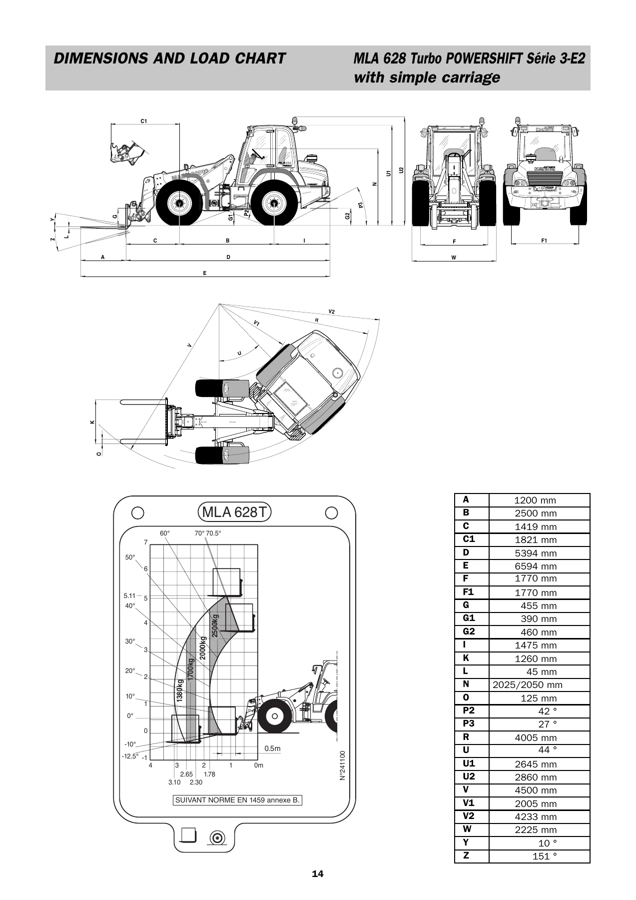
- Group 0 – General Points: characteristics, dimensions and load chart, filters cartridges and belts, lubricants and fuel
- Group 10 – I.C. Engine: engine design, fuel injection lines, fuel injection pumps (Delphi DP210, Bosch EPVE, Delphi STP), fuel injectors, fuel transfer pump, lifter group, rocker shaft, valve mechanism cover, cylinder head valves, cylinder head, turbocharger, exhaust manifold, camshaft, camshaft bearings, engine oil filter, engine oil pump, engine oil pressure, engine oil bypass valve, engine oil pan, crankcase breather, water temperature regulator and housing, water pump, cylinder block, crankshaft, crankshaft seals, connecting rod bearing journal, main bearing journal, connecting rod, piston and rings, piston cooling jet, front housing and covers, gear group (front), flywheel, flywheel housing, crankshaft pulley, fan drive, engine lifting bracket, alternator, starter motor, glow plugs
- Group 10 – Procedures: Disassembly and Assembly section, Systems Operation section, Testing and Adjusting section for the engine
- Group 20 – Transmission: T12000 Powershift gear box and converter, disassembly, operation of the transmission, powerflows and activated solenoids, hydraulic circuits, troubleshooting guide, sectional views and parts identification, assembly instructions, options
- Group 30 – Axle: axle assembly disassembly for the DANA front and rear axles
- Group 40 – Brake: operation and adjustment of the assisted braking system, accumulator charging, pedal height, pressure switch adjustment
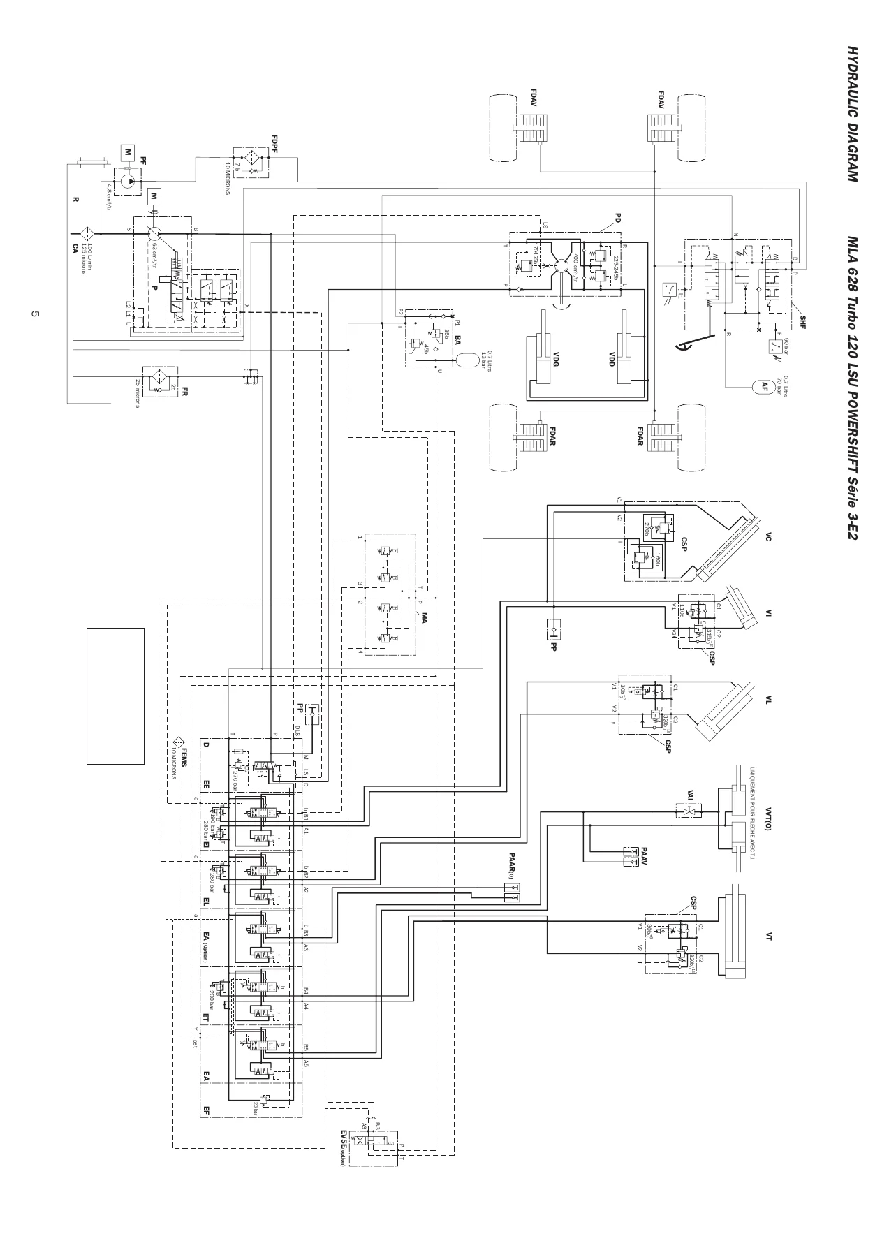
- Group 70 – Hydraulic: cylinder disassembly (lifting, compensation, telescoping, tilting and steering cylinders), hydraulic diagrams
- Group 80 – Electricity: electric diagrams, EGS shift lever operation and self-test functions, longitudinal stability alarm operating and setting
- Group 85 – Air-conditioning: operation and adjustment, component service sheets, startup instructions, maintenance and pressure/temperature checks
IMAGES PREVIEW
What This Repair Manual Gives You
The document is organised by machine group rather than by generic system, so the information follows the way the machine is actually built. Group 10 alone runs from the bare cylinder block and crankshaft through the camshaft, valve train, pistons and rings, cylinder head and gasket, turbocharger, front gear train, flywheel and rear seal, out to the cooling circuit and the charging and starting system. Interleaved with the specification pages are full Disassembly and Assembly procedures, a Systems Operation section explaining how the lubrication, cooling, air inlet and exhaust circuits behave, and a Testing and Adjusting section with valve lash, compression, oil pressure, glow plug and V-belt tests.
The transmission chapter is dedicated to the T12000 power shift unit with torque converter. It explains the converter, pump drive and pressure regulating valve, the input shaft and directional clutches, the range clutches and the output section, then maps every forward and reverse gear to the solenoids and clutches that are energised to obtain it. Hydraulic diagrams accompany each gear, pressure check port numbers are listed alongside the clutch they serve, and the troubleshooting guide works through low clutch pressure, low charging pump output, overheating, a noisy converter and lack of power with cause-and-remedy tables. The rear of the chapter carries sectional views and parts identification for the converter housing, transmission case and plate, torque converter, pump drive, charging pump, reverse idler, forward and reverse shaft, high (4th) and 3rd shaft, 1st and 2nd shaft, output shaft, electric control and drive plate, followed by step-by-step disassembly and reassembly photographs.
For the axles, the Group 30 material deals with the DANA front and rear units including the limited slip differentials and epicyclic hub reducers. Group 40 covers the assisted braking system fitted to these MLA machines, which differs from the arrangement used on MLT and MT models: it explains the accumulator, master cylinder, accumulator charging system and flow divider, then gives the checking and adjusting procedures for accumulator charging pressure, braking assistance pressure, pedal height, accumulator gas charge and the pressure switches. Group 70 handles the hydraulic cylinders individually, with removal and reassembly of the complete stem, piston and locking ring, piston seals and rings, locking ring seals, the thread locking material to use and tightening torques by thread size. Group 80 provides the complete electric diagram with component, fuse, relay and connector lists, plus the EGS gearbox shift lever operation with its LED display, self-test modes and speed sensor installation. Group 85 rounds it out with the air conditioning circuit, coolant R134a characteristics, cooling load by machine, adjustment checks and after-sales product sheets for each component.
Covered Equipment at a Glance
The two machines share the Perkins 1104C-44 family: the 1104C-44T turbocharged unit and the 1104C-44TA turbocharged and cooled unit. Both are four-cylinder in-line, 4400 cm3, 105 mm bore and 127 mm stroke, direct injection, firing order 1-3-4-2. Cooling is by water with a ten-blade puller fan, thermostat start opening at 79 °C and full opening at 93 °C. Transmission is the DANA electro-hydraulic unit with four forward and three reverse speeds and an electro-hydraulic gear reverser. Front and rear axles are DANA with 45 percent limited slip differentials and epicyclic hub reducers. The hydraulic circuit uses a gear pump with flow divider rated at 41 cm3, up to 96 L/min unladen, with lifting, tilting, telescoping and attachment circuits at 250 bar and steering at 175 bar. Braking is a foot-pedal hydraulic servo-brake acting on multidisc brakes immersed in oil on the front and rear wheels, with a mechanical hand lever parking brake on the front wheels.
Why This Manual Matters for the Job
Working on a Powershift telehandler without the manufacturer’s procedures is a gamble on the transmission in particular. The clutch packs, the solenoid logic and the modulation valves are interdependent, and a shift that is made without the correct pressure or clearance will show up later as slipping, overheating or a burnt clutch. This manual gives the exact clutch clearance ranges to check during reassembly, the pressures to look for at each check port, the torque values for the cartridge nuts, the modulation valve housings, the regulator sleeve and the clutch shaft rear bearings, and the Loctite and sealant products to use at each joint. The same applies to the engine: valve lash settings, cylinder head bolt tightening in three stages with an angle gauge, main bearing cap torque, connecting rod torques with the additional turn, and the fuel injection pump locking and timing routines for the Delphi DP210, Delphi STP and Bosch EPVE pumps.
Instant PDF Delivery
The Manitou MLA 628 Powershift Série 3-E2 repair manual is delivered as a downloadable PDF immediately after checkout. There is no shipping, no waiting and no physical binder to lose in the workshop. Keep it on a laptop, tablet or phone for use at the machine, print only the pages you need for a particular job, and return to it as often as required. For anyone maintaining, repairing or restoring an MLA 628 Turbo or MLA 628 – 120 LSU Powershift Série 3-E2, this is the reference that keeps the work inside the manufacturer’s specifications.

Reviews
There are no reviews yet.