
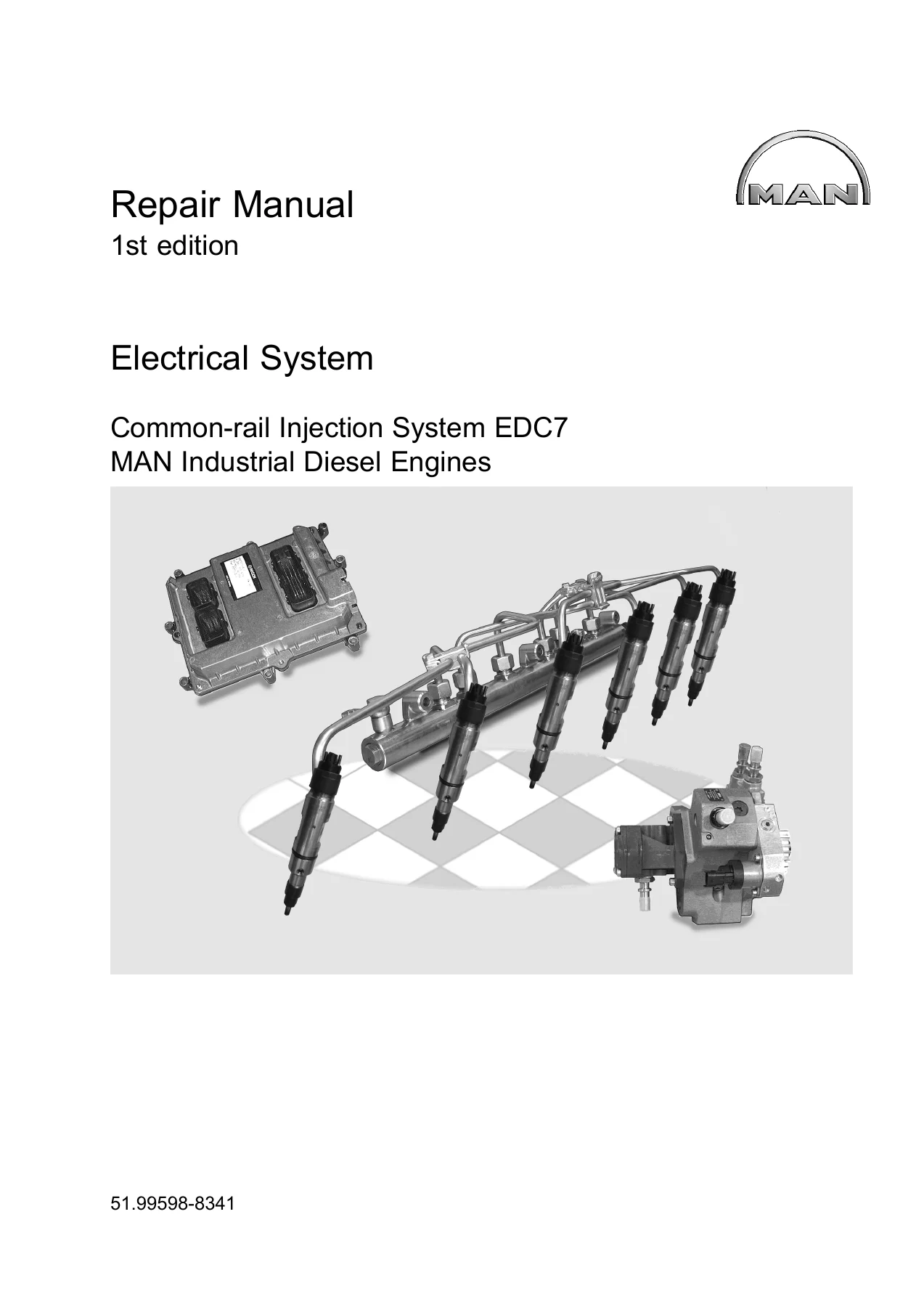
MAN Industrial Diesel Engines EDC7 Common-rail Injection System Repair Manual 51.99598-8341 – PDF Download
Original price was: $59.95.$39.95Current price is: $39.95.
Complete MAN EDC7 common-rail injection system repair manual for D20, D26, D2862 and D2868 industrial diesel engines. Covers diagnostics, component replacement, wiring diagrams, test step lists and fault code troubleshooting. Instant PDF download.
Description
MAN Industrial Diesel Engines EDC7 Repair Manual 51.99598-8341
This PDF repair manual is the complete service documentation for MAN Industrial Diesel Engines equipped with the EDC7 common-rail injection system. It is the same technical publication used by professional technicians to diagnose, repair and maintain the high-pressure fuel system, electronic control unit, sensors, injectors, turbocharger controls and exhaust gas aftertreatment on D20, D26, D2862 and D2868 engines. The manual is published by MAN Truck & Bus AG under document number 51.99598-8341, first edition, with technical status 10.2013.
Whether you are performing a full injector replacement, diagnosing a rail pressure fault, checking the metering unit resistance or tracing a wiring fault through the EDC7 C32 control unit connectors, this MAN EDC7 repair manual provides the pin assignments, test values, wiring diagrams and step-by-step troubleshooting procedures needed to get the job done correctly.
File Details
- Manual Type: Repair Manual (Electrical System and Common-rail Injection System)
- Brand: MAN
- Models Covered: Industrial Diesel Engines D20, D26, D2862, D2868
- System: EDC7 Common-rail Injection System
- Document Number: 51.99598-8341
- Edition: 1st Edition
- Technical Status: 10.2013
- Copyright: 2012 MAN Truck & Bus AG
- Language: English
- Format: PDF
- Page Count: 286 pages
Chapters Covered
- Introduction
- Safety Instructions
- Device Description
- Component Description / Installation Positions
- Diagnosis
- Wiring Diagrams
- Test Step Lists
- Hydraulic Test Step List
- Troubleshooting with MAN-cats
- Troubleshooting Program
Introduction and Safety Instructions
The opening chapters establish the safety framework for working on the common-rail system. Specific warnings cover high-pressure line handling (fuel pressures up to 1800 bar), electrical system isolation, battery handling, air-conditioning refrigerant safety, and the critical cleanliness requirements for diesel injection work. A dedicated section addresses pacemaker safety and the correct procedure for depressurising the rail before opening any high-pressure connection. The chapter also explains the limited liability policy for non-MAN parts and the correct handling of AdBlue urea solution.
Device Description and Functional Description
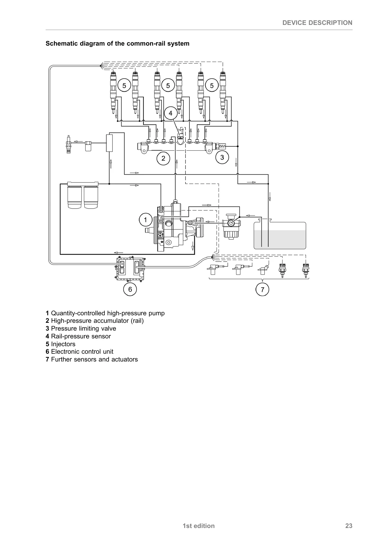
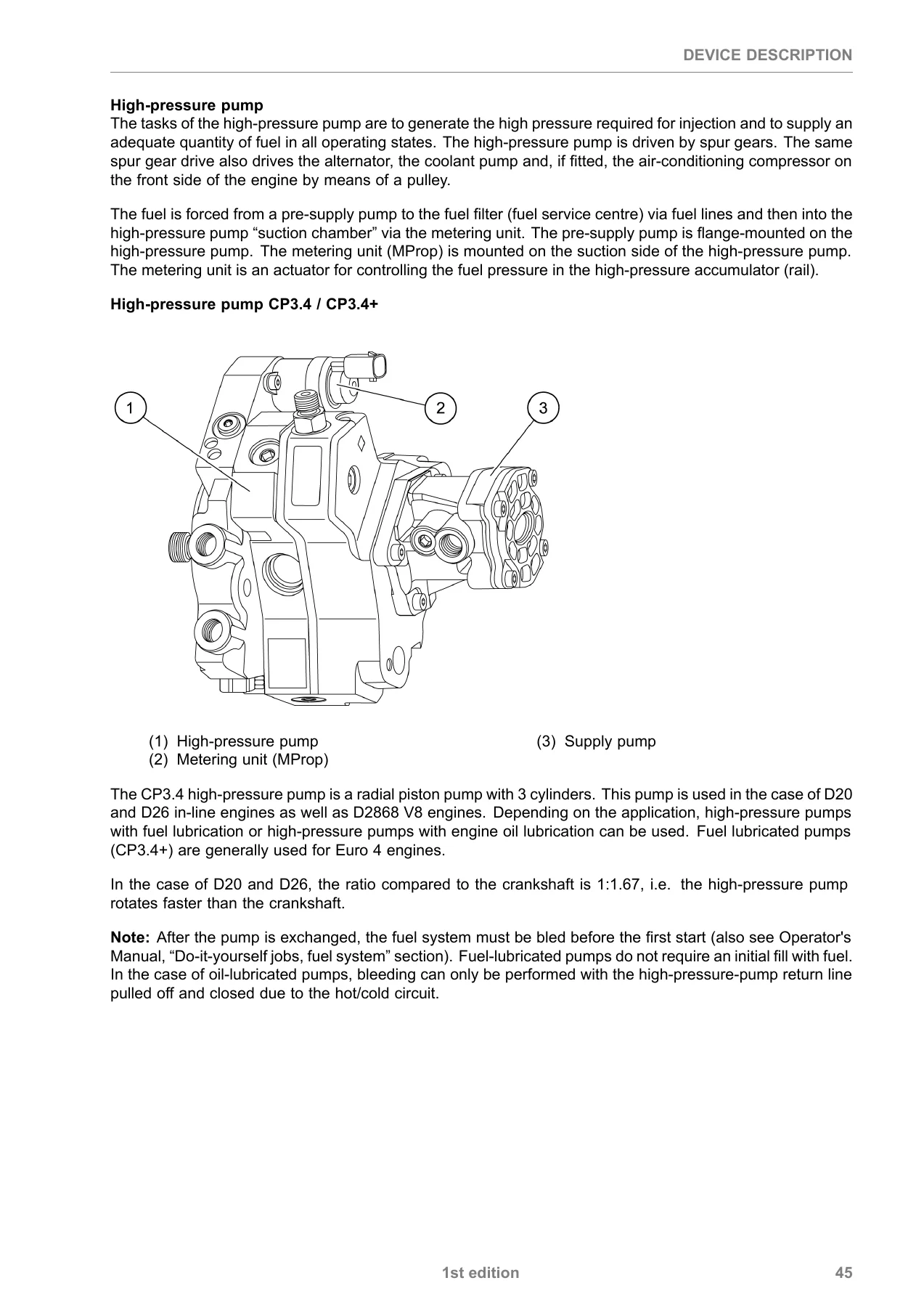
This is the core technical reference for the EDC7 system. It begins with the common-rail system structure and operation, then moves into the functional description of the EDC7 control unit (A435, A570), including its master/slave configuration for V-engine applications. Every major component is described in detail: the CP3.4/CP3.4+ high-pressure pump, the metering unit (MProp), the high-pressure accumulator (rail), the pressure limiting valve, the rail pressure sensor, the injectors, crankshaft and camshaft speed sensors, oil pressure sensor, fuel pressure sensor, charge pressure sensors (Kavlico and Bosch LDF 6/LDF 6T), charge air temperature sensor, coolant temperature sensor, fuel temperature sensor, exhaust gas temperature sensors, NOx sensor, oxygen sensor, exhaust gas differential and relative pressure sensors, turbocharger proportional valves, and the position-controlled E-EGR controller. Each component section includes connector pin assignments, wiring details, sensor curves and measurement tables where applicable.
Control Unit Pin Assignments
The manual contains complete pin assignment tables for every EDC7 C32 control unit variant: EC Stage IIIB/Tier 4i (engine connector A, vehicle connector B, injector connector C), EC Stage IIIB/EGR, Master EC Stage IIIB/Tier 4i V8 and V12, and Slave EC Stage IIIB/Tier 4i V8 and V12. Each table lists pin number, line number/colour, function, and the corresponding control unit pin for both A435 and A570 units where applicable. These tables are essential for electrical diagnostics, harness repair and control unit replacement.
Component Description and Installation Positions
This chapter provides photographic installation position references for every major component across D20/D26 in-line engines and D2868 V8 engines. Each component description is followed by one or more images showing its physical location on the engine, with arrows highlighting the exact position. Covered components include the EDC7 control unit, high-pressure pump, metering unit, rail, pressure limiting valve, rail pressure sensor, injectors, speed sensors, oil pressure sensor, fuel pressure sensor, charge pressure sensor, temperature sensors, NOx sensor, oxygen sensor, exhaust gas pressure sensors, turbocharger proportional valves and EGR controller.
Diagnosis
The diagnosis chapter explains the K-line system structure and diagnosis socket connections, including the 12-pin MAN diagnosis socket (X200) and the 16-pin HD-OBD diagnosis socket to ISO 15031-3. It covers the adapter cable for HD-OBD applications, fault memory structure, fault code identification (SPN), failure mode identification (FMI), fault priority levels and the self-healing counter for sporadic faults. The OBD fault memory operation is explained in detail, including the conditions for MIL illumination, fault debouncing over driving cycles, and the long-term fault memory retention period. Torque limiter operation and the procedure for withdrawing torque limiting and resetting the MIL are also documented.
Fault Code List (SPN)
An extensive SPN (Suspect Parameter Number) fault code list documents every diagnostic trouble code the EDC7 system can generate. Each entry includes the SPN plain text description, the system response, and notes on fault conditions. Codes cover injector circuits (SPN 651-656), rail pressure monitoring (SPN 3775-3781), speed sensor faults (SPN 3752, 3753), CAN communication errors (SPN 3673, 3804, 3806, 3819-3822), sensor supply faults (SPN 1079, 1080), EGR system faults (SPN 3004, 3746, 3850-3853), oxygen sensor faults (SPN 3836-3859, 3938), exhaust gas temperature faults (SPN 3792, 3793, 3811, 3812), and many more.
Test Step Lists
The electrical test step lists provide structured measurement procedures for each EDC7 C32 variant. They are divided into tests with the engine stopped (ignition OFF, control unit disconnected) and tests with the engine stopped or running (control unit connected). Each test specifies the measurement points (PIN+ and PIN-), the desired value, and space for recording actual values. Coverage includes speed sensors, metering unit, temperature sensors, oxygen sensor, pressure sensor supplies and grounds, CAN connections, injector resistances, IMR relay, and control unit voltage supplies. Separate test step lists are provided for 6-cylinder in-line engines, Master-Slave V8 and V12 configurations, and the AdBlue dosing control unit DCU15.
Hydraulic Test Step List
This chapter covers troubleshooting in the fuel system, with procedures for checking the low-pressure circuit, overflow valve, pressure retaining valve, total leakage volume, individual injector leakage, and high-pressure pump delivery rate. It includes the catalogue of questions for problematic cases, frequent faults and their corrections, and specific procedures for engine starting problems, white smoke, black smoke, engine knock, excess pressure in the fuel tank, and engine running irregularities. A replacement metering unit combination table helps identify the correct test component for each high-pressure pump variant.
Troubleshooting with MAN-cats
This section documents the diagnostic routines available through the MAN-cats system: compression test, rev-up test (TRUP), cylinder shut-off test, high-pressure test, and smooth-running control. Each procedure includes requirements, step-by-step instructions, expected results and evaluation criteria. The smooth-running control section explains how correction quantities are displayed and interpreted to identify cylinders with poor power output.
Troubleshooting Program
The troubleshooting program is organised by SPN fault code and provides detailed test procedures for each fault. Each entry includes monitoring strategy, effect of fault, possible faults (FMI), test measurements, and remedy instructions. This section covers the full range of EDC7 diagnostics from injector circuit faults and rail pressure deviations to CAN communication errors, sensor plausibility checks, EGR system faults, oxygen sensor faults and exhaust gas aftertreatment monitoring.
Wiring Diagrams
The wiring diagrams chapter provides complete system overviews for all EDC7 C32 variants: EC Stage IIIB/Tier 4i OBD 1 with NOx monitoring, EC Stage IIIB/Tier 4i Master-Slave V8, EC Stage IIIB/Tier 4i Master-Slave V12, EC Stage IIIB/EGR, and the AdBlue dosing control unit DCU15. Each overview includes a legend identifying every component, sensor, actuator, fuse, connector and earth point in the circuit.
What This MAN EDC7 Repair Manual Enables You to Do
This is not a generic overview or a collection of specifications. It is the complete repair documentation for the EDC7 common-rail system as fitted to MAN industrial diesel engines. With this manual, you can:
- Diagnose and repair every fault code the EDC7 system can generate, using the SPN fault list and the detailed troubleshooting program
- Perform electrical measurements on the control unit connectors with confidence, using the pin assignment tables and test step lists
- Remove and install the high-pressure pump, metering unit, rail, pressure limiting valve, rail pressure sensor and injectors correctly, following the component description and installation position chapters
- Check the low-pressure fuel circuit, measure total and individual injector leakage, and test the high-pressure pump delivery rate using the hydraulic test step list
- Trace wiring faults through the complete system wiring diagrams for every EDC7 C32 variant
- Understand the master/slave control unit configuration on V8 and V12 engines and diagnose CAN communication faults
- Correctly handle the safety-critical aspects of common-rail work, including depressurisation, cleanliness requirements and high-pressure line handling
Correct procedures and accurate specifications matter in common-rail diesel work. A rail pressure fault misdiagnosed as a sensor problem when the real cause is a leaking injector will cost far more than the manual. The torque values, test pressures, resistance ranges and fault code interpretations in this document are the ones the system was designed around.
IMAGES PREVIEW
Instant PDF delivery. This MAN Industrial Diesel Engines EDC7 repair manual is available for immediate download after payment. No shipping, no waiting. The PDF can be viewed on any device — laptop, tablet or smartphone — and printed pages can be taken directly to the workshop. Whether you are a fleet workshop, an independent diesel specialist or a technician maintaining MAN industrial engines, this manual gives you the complete technical reference for the EDC7 common-rail injection system.
Reviews
There are no reviews yet.