★ TRUSTED BY 321,897+ PROFESSIONALS WORLDWIDE
🏢
Trusted Business
Verified & Licensed
🛡️
Virus Free Files
100% Safe Downloads
🔒
Secure Payment
SSL Protected
Instant Delivery
Available Immediately
Sale!

Claas Lexion 480 Combine Harvester Repair Manual 188678.1 — January 2004 Edition

Original price was: $39.95.Current price is: $23.95.

Complete CLAAS Lexion 480 repair manual covering threshing mechanism, cleaning unit, hydraulic system, engine, drives, final drives, and more. 1018 pages, document number 188 678.1, January 2004 edition.

Instant PDF Download
Available immediately
💾
Save to Your Device
Download & keep forever
🛡️
Antivirus Scanned
100% virus-free
🌍
Trusted Worldwide
175,000+ customers

Description

File Details

  • Manual Type: Repair Manual (RHB)
  • Brand: CLAAS
  • Model: Lexion 480
  • Document Number: 188 678.1
  • Edition: January 2004 (GB — 01.04)
  • Language: English
  • Page Count: 1018
  • Format: PDF

IMAGES PREVIEW

Claas Lexion 480 Combine Harvester Repair Manual 188678.1 — January 2004 Edition — PDF page 1 preview
Claas Lexion 480 Combine Harvester Repair Manual 188678.1 — January 2004 Edition — PDF page 35 preview
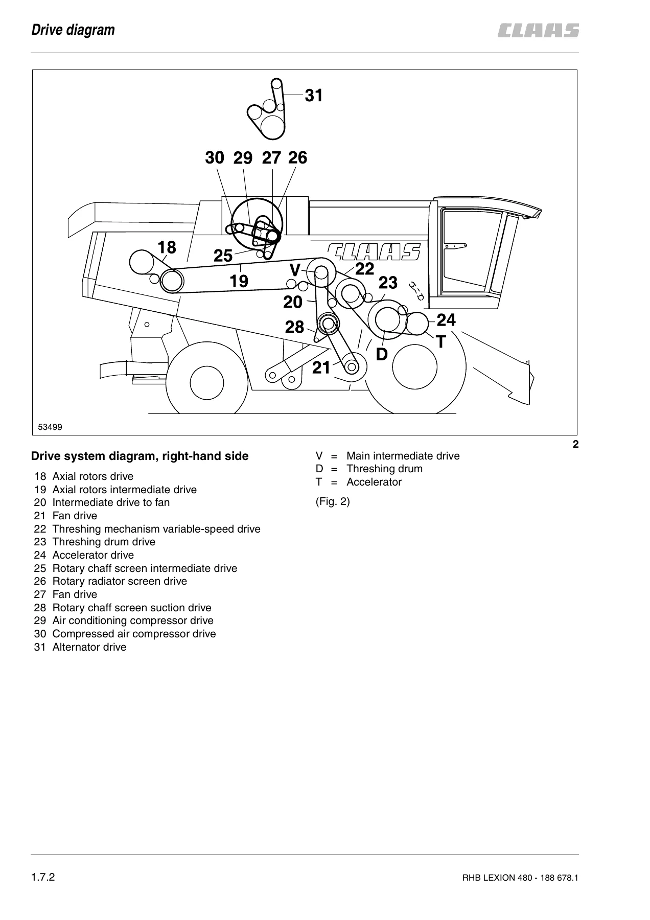
Claas Lexion 480 Combine Harvester Repair Manual 188678.1 — January 2004 Edition — PDF page 40 preview

Chapters Covered

  • 1. General Information — safety rules, repair information, tightening torques, specifications, lubricants chart, hydraulic pressure values, sectional view and drive diagrams
  • 2. Operator’s Platform — compressor-type air conditioner, steering, parking brake, foot brake, engine electric system
  • 3. Threshing Mechanism — feed rake conveyor, threshing concave, accelerator, threshing drum, impeller, axial rotors
  • 4. Cleaning Unit — return pan, sieve pan, preparation floor, 3-D sieve pan control system, rocker arm drive, cleaning fan
  • 5. Grain Delivery — returns elevator, grain elevator, grain tank unloading
  • 6. Straw Discharge — straw chopper, uni-spreader
  • 7. Drives — drive belts, left-hand and right-hand drive belts, cutterbar drive, left-hand and right-hand threshing mechanism drive, threshing drum reduction gearbox, threshing mechanism intermediate drive, grain tank unloading drive, chopper drive, straw spreader drive, uni-spreader drive, sieve pan drive, fan drive, axial rotor drive, engine output, rotary screen drive, final drives, manual gearbox, brake, steering axle
  • 8. Machine Body — rotary screen, drive axle
  • 9. Hydraulic System — oil cooler, maintenance, hydraulic pumps, hydrostatic fixed displacement motors, hydraulic cylinders (high-pressure circuit, low-pressure hydraulics, steering hydraulics), valve combinations
  • 10. Engine — cooling system, fuel system, engine removal and installation
  • 11. Index

The Claas Lexion 480 Repair Manual 188678.1 is a comprehensive workshop document spanning over one thousand pages, dedicated entirely to the CLAAS Lexion 480 combine harvester. This January 2004 edition covers every major system on the machine — from the feed rake conveyor and threshing concave through to the axial rotors, cleaning fan, grain tank unloading, hydraulic circuits, and the Mercedes OM 441 LA engine. Each section is structured with step-by-step removal, disassembly, assembly, and installation procedures, supported by measurements, tightening torques, and special tool references where applicable. The manual also includes drive diagrams, a sectional view of the machine, a lubricants chart, hydraulic pressure values, and basic concave settings — making it a complete reference for anyone maintaining or repairing the Lexion 480.

Complete PDF Bookmark Tree

Complete Bookmarks

The complete bookmarks in the “Claas Lexion 480 Combine Harvester Repair Manual 188678.1 — January 2004 Edition” are as follows:

Contentsp. 3
General informationp. 15
Generalp. 17
Introductionp. 17
Introduction to the CLAAS Repair Manualp. 18
Key to symbolsp. 19
Safety Rulesp. 21
Important noticep. 21
Identification of warning and danger signsp. 22
Correct use of the machinep. 22
General safety and accident prevention regulationsp. 22
Leaving the machinep. 23
Compressor-type air conditionerp. 23
Maintenancep. 23
Basic rulep. 23
Pressure accumulatorp. 23
General repair informationp. 25
Reason of damagep. 25
Spare partsp. 25
Enginep. 25
Gearboxesp. 25
Alternatorp. 25
Tensioning the steel roller chainsp. 25
Taper ring fastenersp. 25
Self-locking boltsp. 25
Liquid locking compoundp. 26
Correct installation of lock collar bearingsp. 26
Correct installation of adapter sleeve bearingsp. 26
Ferrule fittings on hydraulic linesp. 26
Progressive ring fittings on hydraulic linesp. 27
Taper fittings on hydraulic linesp. 27
Weldingp. 28
Some advice for speedy and correct repair work:p. 28
Tightening torquesp. 29
Boltsp. 29
Hydraulic fittingsp. 30
Brake line screw jointsp. 31
Wheel boltsp. 32
Safety featuresp. 32
Specificationsp. 33
Lubricants chartp. 33
Hydraulic pressure valuesp. 34
Sectional view of machinep. 35
Drive diagramp. 39
Drive diagram, left-handp. 39
Drive system diagram, right-hand sidep. 40
Operator's platformp. 41
Air conditionerp. 43
Important instructions regarding the compressor-type air conditioning systemp. 43
Important instructions regarding the installation of parts in the compressor-type air conditionerp. 44
Air conditioning system – Topping up refrigerantp. 45
Checking / topping up the refrigerant oil level at the air conditioner compressorp. 46
Topping up refrigerant oilp. 47
Removing the condenserp. 47
Refitting the condenserp. 48
Removing the air conditioner compressorp. 49
Installing the air conditioner compressorp. 50
Removing the air conditioner compressor electro-magnetic clutchp. 50
Air conditioner compressor Sanden Sd 7h 15, disassembledp. 54
Installing the air conditioner compressor electro-magnetic clutchp. 55
Removing the air conditioner compressor cylinder head / cylinder head gasketp. 57
Installing the air conditioner compressor cylinder head / cylinder head gasketp. 58
Removing the air conditioner compressor shaft sealp. 59
Installing the air conditioner compressor shaft sealp. 61
Removing the expansion valvep. 62
Air conditioning system (cab side), disassembledp. 64
Installing the expansion valvep. 65
Removing the thermostatp. 65
Installing the thermostatp. 67
Removing the evaporatorp. 68
Installing the evaporatorp. 69
Removing the filter receiver drierp. 71
Filter receiver drier, disassembledp. 72
Installing the filter receiver drierp. 72
Steeringp. 75
Scenes of failures on the Orbitrol steering unitp. 75
External leaksp. 75
Internal leaksp. 75
Removing the steering columnp. 76
Disassembling the steering columnp. 78
Steering column, disassembled:p. 81
Assembling the steering columnp. 82
Installing the steering columnp. 83
Removing the valve block from the Orbitrolp. 85
Installing the valve block on the Orbitrolp. 86
Removing the Orbitrolp. 88
Orbitrol, disassembledp. 88
Installing the Orbitrolp. 89
Parking brakep. 93
Removing the parking brakep. 93
Installing the parking brakep. 94
Foot brakep. 95
Removing the master brake cylinderp. 95
Master brake cylinder, disassembledp. 95
Assembling the master brake cylinderp. 95
Installing the master brake cylinderp. 96
Adjusting the master brake cylinderp. 96
Engine electric systemp. 97
Alternatorp. 97
Threshing mechanismp. 99
Feed rake conveyorp. 101
Removing the feed rake conveyorp. 101
Installing the feed rake conveyorp. 103
Removing the intercepting piecep. 104
Installing the intercepting piecep. 104
Removing the feed rake conveyor suction blowerp. 105
Disassembling the feed rake conveyor suction blowerp. 105
Feed rake conveyor suction blower, disassembled:p. 107
Assembling the feed rake conveyor suction blowerp. 108
Installing the feed rake conveyor suction blowerp. 109
Removing the top feed rake shaftp. 109
Feed rake top shaft, disassembledp. 114
Installing the feed rake top shaftp. 115
Removing the bottom feed rake rollerp. 119
Bottom feed rake roller, disassembledp. 121
Assembling the bottom feed rake rollerp. 121
Installing the bottom feed rake rollerp. 121
Replacing the wooden ledgesp. 122
Removing the intermediate floorp. 123
Installing the intermediate floorp. 125
Replacing the runnersp. 125
Removing the intermediate drive shaftp. 126
Intermediate drive shaft, disassembledp. 130
Installing the intermediate drive shaftp. 131
Removing the reverser drivep. 132
Reverser drive, disassembledp. 134
Installing the reverser drivep. 135
Replacing the feeder chainsp. 135
Threshing concavep. 139
Removing the stone trapp. 139
Installing the stone trapp. 139
Removing the preconcavep. 140
Preconcave, disassembledp. 143
Installing the preconcavep. 144
Removing the main concavep. 145
Main concave, disassembledp. 148
Installing the main concavep. 150
Basic concave settingp. 154
Adjusting the concave potentiometerp. 159
Learning the limit stopsp. 159
Learning the limit stopsp. 160
Acceleratorp. 161
Removing the bearing assembly and the shaft on the right-hand sidep. 161
Disassembling the right-hand bearing assemblyp. 163
Assembling the right-hand bearingp. 163
Installing the right-hand bearing assembly and shaftp. 165
Removing the bearing assembly on the left-hand sidep. 168
Disassembling the left-hand bearing assemblyp. 170
Assembling the left-hand bearing assemblyp. 171
Installing the left-hand bearing assemblyp. 172
Replacing the accelerator capsp. 173
Removing the acceleratorp. 174
Accelerator, disassembledp. 177
Installing the acceleratorp. 178
Threshing drump. 183
Removing the right-hand drum bearing assemblyp. 183
Disassembling the right-hand drum bearingp. 185
Right-hand drum bearing, disassembled:p. 186
Installing the right-hand drum bearingp. 187
Removing the left-hand drum bearing assemblyp. 188
Disassembling the left-hand drum bearingp. 190
Left-hand drum bearing assembly, disassembled:p. 190
Installing the left-hand drum bearing assemblyp. 191
Removing the threshing drump. 192
Threshing drum, disassembledp. 194
Renewing the beater barsp. 195
Removing the threshing drum shaftp. 196
Installing the threshing drum shaftp. 198
Installing the threshing drump. 199
Impellerp. 201
Removing the right-hand impeller bearingp. 201
Installing the right-hand impeller bearingp. 203
Removing the left-hand impeller bearingp. 203
Installing the left-hand impeller bearingp. 205
Removing the impellerp. 206
Installing the impellerp. 208
Removing the flanged shaft (from serial no. …)p. 209
Impeller disassembled (from serial no. …)p. 210
Installing the flanged shaftp. 211
Removing the impeller shaft (up to serial no. …)p. 212
Impeller disassembled (up to serial no. …)p. 213
Installing the impeller shaft (up to serial no. …)p. 214
Axial rotorsp. 215
Removing the separation gratesp. 215
Installing the separation gratesp. 217
Removing the separating jacketp. 217
Installing the separating jacketp. 220
Removing the axial rotor supporting armp. 221
Disassembling the axial rotor supporting armp. 222
Supporting arm, disassembled:p. 223
Installing the axial rotor supporting armp. 223
Removing the axial rotorp. 225
Installing the axial rotorp. 227
Removing the hybrid unit completelyp. 228
Installing the hybrid unitp. 236
Cleaning unitp. 239
Return panp. 241
Lowering the return pan (from serial no. …)p. 241
Raising and installing the return pan (from serial no. …)p. 242
Removing the return panp. 243
Rear rocker arm, disassembledp. 245
Installing the return panp. 245
Sieve panp. 247
Removing and installing the sievesp. 247
Removing the upper sieves (from serial no. …)p. 247
Removing the lower sieves (from serial no. …)p. 249
Installing the sieves (from serial no. …)p. 250
Tightening torques of axial mountings for the upper and lower sieves (from serial no. …)p. 250
Sieves – Basic setting (electric sieve adjustment – from serial no. …)p. 251
Removing the upper sieves (up to serial no. …)p. 251
Removing the lower sieves (up to serial no. …)p. 253
Installing the sieves (up to serial no. …)p. 254
Tightening torques of axial mountings for the upper and lower sieves (up to serial no. …)p. 255
Sieves – Basic setting (electric sieve adjustment – up to serial no. …)p. 255
Removing the 3-D upper sieve framep. 256
3-D upper sieve frame, disassembledp. 261
Installing the 3-D upper sieve framep. 262
Removing the sieve panp. 263
Sieve pan, disassembledp. 266
Installing the sieve panp. 267
Checking and adjusting the alignment of preparation floor and sieve panp. 270
Preparation floorp. 271
Removing the preparation floorp. 271
Preparation floor, disassembledp. 273
Installing the preparation floorp. 274
3-D sieve pan control systemp. 275
Adjusting the 3-D sieve pan control systemp. 275
Adjusting pivot arm (A) with the “3-D gauge”p. 276
Rocker arm drivep. 277
Removing the intermediate drive shaft for the rocker arm drivep. 277
Intermediate drive shaft for rocker arm drive, disassembledp. 278
Installing the intermediate drive shaft for the rocker arm drivep. 279
Cleaning fanp. 281
Removing the bearings of the cleaning fanp. 281
Cleaning fan bearing, disassembledp. 284
Installing the cleaning fan bearingp. 284
Removing the cleaning fan shaftp. 285
Removing the centre cleaning fan bearingp. 289
Centre cleaning fan bearing, disassembledp. 289
Installing the cleaning fan shaftp. 290
Removing the cleaning fan rotorsp. 291
Installing the cleaning fan rotorsp. 291
Removing the cleaning fan housingp. 292
Installing the cleaning fan housingp. 294
Grain deliveryp. 295
Returns elevatorp. 297
Removing the returns elevator chainp. 297
Installing the returns elevator chainp. 299
Removing the top returns augerp. 299
Installing the top returns augerp. 301
Removing the returns elevatorp. 302
Disassembling the returns elevatorp. 303
Assembling the returns elevatorp. 305
Installing the returns elevatorp. 305
Removing the returns elevator bootp. 306
Installing the returns elevator bootp. 307
Removing the lower returns augerp. 307
Installing the lower returns augerp. 309
Grain elevatorp. 311
Removing the clean grain elevator chainp. 311
Installing the clean grain elevator chainp. 312
Removing the clean grain elevator headp. 313
Dismantling the clean grain elevator headp. 314
Clean grain elevator head, disassembled:p. 316
Assembling and installing the clean grain elevator headp. 317
Removing the clean grain elevator shaftp. 317
Installing the grain elevator shaftp. 318
Removing the clean grain elevator bootp. 319
Installing the clean grain elevator bootp. 320
Removing the clean grain augerp. 320
Installing the clean grain augerp. 323
Removing the grain tank filler augerp. 324
Removing the grain tank filler auger angle drivep. 325
Disassembling the grain tank filler auger angle drivep. 326
Grain tank filler auger, disassembled:p. 327
Installing the grain tank filler augerp. 328
Grain tank unloadingp. 331
Removing the grain tank cross augerp. 331
Grain tank cross augers, disassembledp. 334
Installing the grain tank cross augerp. 335
Removing the vertical grain tank unloading augerp. 337
Installing the vertical grain tank unloading augerp. 340
Removing the horizontal grain tank unloading augerp. 341
Installing the horizontal grain tank unloading augerp. 343
Removing the lower grain tank unloading angle drive (from serial no. …)p. 343
Disassembling the lower grain tank unloading angle drive (from serial no. …)p. 345
Lower grain tank unloading angle drive, disassembled: (from serial no. …)p. 348
Assembling the lower grain tank unloading angle drive (from serial no. …)p. 349
Installing the lower grain tank unloading angle drive (from serial no. …)p. 352
Removing the lower grain tank unloading angle drive (up to serial no. …)p. 353
Disassembling the lower grain tank unloading angle drive (up to serial no. …)p. 354
Lower grain tank unloading angle drive, disassembled: (up to serial no. …)p. 357
Assembling the lower grain tank unloading angle drive (up to serial no. …)p. 358
Installing the lower grain tank unloading angle drive (up to serial no. …)p. 361
Removing the upper grain tank unloading angle drivep. 362
Disassembling the upper grain tank unloading angle drivep. 363
Upper grain tank unloading angle drive, disassembled:p. 364
Assembling the upper grain tank unloading angle drivep. 365
Installing the upper grain tank unloading angle drivep. 368
Removing the grain tank unloading tubep. 369
Refitting the unloading auger tubep. 370
Removing the grain tank unloading tube elbowp. 370
Installing the grain tank unloading tube elbowp. 371
Removing the vertical unloading auger tubep. 371
Installing the vertical unloading auger tubep. 372
Straw dischargep. 373
Straw chopperp. 375
Removing the right-hand straw chopper bearingp. 375
Right-hand straw chopper bearing assembly, disassembledp. 377
Installing the right-hand straw chopper bearingp. 377
Removing the left-hand straw chopper bearingp. 379
Left-hand straw chopper bearing assembly, disassembledp. 380
Installing the left-hand straw chopper bearingp. 380
Removing the cutting cylinderp. 381
Cutting cylinder, disassembledp. 385
Installing the cutting cylinderp. 386
Replacing the free-swinging knivesp. 387
Uni-spreaderp. 391
Removing the fan blade bearingsp. 391
Assembling and installing the fan blade bearingp. 398
Drivesp. 403
Drive beltsp. 405
General Informationp. 405
Drive diagramp. 406
Drive diagram, left-handp. 406
Drive system diagram, right-hand sidep. 407
Left-hand drive beltsp. 409
Removing the cutterbar drive belt (1) (Cutterbar drive without variable-speed drive)p. 409
Installing and adjusting the cutterbar drive belt (1) (Cutterbar drive without variable-speed drive)p. 410
Removing the cutterbar drive belt (2) (Cutterbar drive with variable-speed drive)p. 411
Installing and adjusting the cutterbar drive belt (2) (Cutterbar drive with variable-speed drive)p. 412
Removing the cutterbar variable-speed drive belt (3)p. 413
Installing and adjusting the cutterbar variable-speed drive belt (3)p. 414
Removing the impeller drive belt (4)p. 415
Installing and adjusting the impeller drive belt (4)p. 416
Removing the cutterbar intermediate drive belt (5)p. 417
Installing and adjusting the cutterbar intermediate drive belt (5)p. 418
Removing the uni-spreader hydraulic pump drive belt (6)p. 419
Installing and adjusting the uni-spreader hydraulic pump drive belt (6)p. 419
Removing the main intermediate drive belt (7)p. 420
Installing and adjusting the main intermediate drive belt (7)p. 422
Removing the grain tank unloading intermediate drive belt (8)p. 424
Installing and adjusting the grain tank unloading intermediate drive belt (8)p. 425
Removing the straw chopper intermediate drive belt (9)p. 426
Installing and adjusting the straw chopper intermediate drive belt (9)p. 427
Removing the straw chopper drive belts (10 and 11)p. 428
Installing and adjusting the straw chopper drive belts (10 and 11)p. 430
Removing the uni-spreader intermediate drive belt (12)p. 431
Installing and adjusting the uni-spreader intermediate drive belt (12)p. 432
Removing the sieve pan intermediate drive belt (13)p. 433
Installing and adjusting the sieve pan intermediate drive belt (13)p. 434
Removing the sieve pan intermediate drive belt (14)p. 435
Installing and adjusting the sieve pan intermediate drive belt (14)p. 436
Removing the sieve pan drive belt (15)p. 437
Installing and adjusting the sieve pan drive belt (15)p. 439
Removing the uni-spreader drive belt (16)p. 440
Installing and adjusting the uni-spreader drive belt (16)p. 441
Removing the grain tank unloading drive chain (17)p. 442
Installing and adjusting the grain tank unloading drive chain (17)p. 443
Right-hand drive beltsp. 445
Adjusting the axial rotor step drive (18)p. 445
Adjusting the axial rotor intermediate drive (19)p. 446
Removing the fan intermediate drive belt (20)p. 447
Installing and adjusting the fan intermediate drive belt (20)p. 448
Removing the fan drive belt (21)p. 449
Installing and adjusting the fan drive belt (21)p. 449
Removing the threshing mechanism variable-speed drive belt (22)p. 450
Installing and adjusting the threshing mechanism variable-speed drive belt (22)p. 451
Removing the threshing drum drive belt (23)p. 452
Installing and adjusting the threshing drum drive belt (23)p. 453
Removing the accelerator drive belt (24)p. 454
Installing and adjusting the accelerator drive belt (24)p. 455
Removing the radiator chaff screen intermediate drive belt (25)p. 456
Installing and adjusting the rotary chaff screen intermediate drive belt (25)p. 457
Removing the radiator chaff screen drive belt (26)p. 458
Installing and adjusting the rotary chaff screen drive belt (26)p. 458
Removing the fan drive belt (27)p. 459
Installing and adjusting the fan drive belt (27)p. 460
Removing the suction blower drive belt (28)p. 461
Installing and adjusting the suction blower drive belt (28)p. 462
Removing the air conditioner compressor drive belt (29)p. 463
Installing and adjusting the air conditioner compressor drive belt (29)p. 464
Removing the compressed-air compressor drive belt (30)p. 465
Installing and adjusting the compressed-air compressor drive belt (30)p. 466
Removing the alternator drive belt (31)p. 467
Installing and adjusting the alternator drive belt (31)p. 468
Removing the feed rake conveyor suction blower drive belt (34)p. 470
Installing and adjusting the feed rake conveyor suction blower drive belt (34)p. 471
Removing the straw spreader drive belt (36)p. 472
Installing and adjusting the straw spreader drive belt (36)p. 473
Cutterbar drivep. 477
Removing the front pulley of cutterbar drive (1)p. 477
Installing the front pulley of cutterbar drive (1)p. 478
Removing the deflection pulley of cutterbar drive (1)p. 478
Deflection pulley of cutterbar drive (1), disassembledp. 479
Installing the deflection pulley of cutterbar drive (1)p. 479
Removing the slip clutch of cutterbar drive (1)p. 479
Installing the slip clutch of cutterbar drive (1)p. 480
Replacing the slip clutch linings of cutterbar drive (1)p. 481
Slip clutch of cutterbar drive (1), dismantledp. 481
Removing the jockey pulley of cutterbar drive (1)p. 483
Jockey pulley of cutterbar drive (1), disassembledp. 483
Removing the rear pulley of cutterbar drive (1) (up to serial no. …)p. 483
Dismantling the rear pulley of cutterbar drive (1) (up to serial no. …)p. 486
Rear pulley of cutterbar drive (1), disassembled: (up to serial no. …)p. 488
Assembling the rear pulley of cutterbar drive (1) (up to serial no. …)p. 489
Installing the rear pulley of cutterbar drive (1) (up to serial no. …)p. 491
Removing the rear pulley of cutterbar drive (1) (from serial no. …)p. 493
Dismantling the rear pulley of cutterbar drive (1) (from serial no. …)p. 496
Rear pulley of cutterbar drive (1), disassembled: (from serial no. …)p. 498
Assembling the rear pulley of cutterbar drive (1) (from serial no. …)p. 499
Installing the rear pulley of cutterbar drive (1) (from serial no. …)p. 500
Removing the cutterbar variable-speed pulley assembly (spring-loaded)p. 502
Disassembling the cutterbar variable-speed pulley assembly (spring-loaded)p. 503
Cutterbar variable-speed pulley assembly (spring-loaded), disassembled:p. 506
Assembling the cutterbar variable-speed pulley assembly (spring-loaded)p. 507
Installing the cutterbar variable-speed pulley assembly (spring-loaded)p. 511
Removing the cutterbar drive V-belt pulley when a cutterbar variable-speed drive is fittedp. 513
Disassembling the cutterbar drive V-belt pulley when a cutterbar variable-speed drive is fittedp. 513
Cutterbar drive V-belt pulley with a cutterbar variable-speed drive fitted, disassembled:p. 515
Assembling the cutterbar drive V-belt pulley with a cutterbar variable-speed drive fittedp. 516
Installing the cutterbar drive V-belt pulley with a cutterbar variable-speed drive fittedp. 518
Removing and disassembling the cutterbar drive deflection pulley (2) with a cutterbar variable-sp…p. 518
Assembling and installing the cutterbar drive deflection pulley (2) with a cutterbar variable-spe…p. 519
Removing the cutterbar variable-speed pulley assembly (hydraulic)p. 519
Disassembling the cutterbar variable-speed pulley assembly (hydraulic)p. 522
Cutterbar variable-speed pulley assembly (hydraulic), disassembled:p. 524
Assembling the cutterbar variable-speed pulley assembly (hydraulic)p. 526
Installing the cutterbar variable-speed pulley assembly (hydraulic)p. 527
Removing the cutterbar clutchp. 528
Cutterbar clutch, disassembledp. 535
Installing the cutterbar clutchp. 536
Left-hand threshing mechanism drivep. 543
Removing the threshing mechanism drive pulley assemblyp. 543
Threshing mechanism drive pulley assembly, disassembledp. 549
Installing the threshing mechanism drive pulley assemblyp. 550
Right-hand threshing mechanism drivep. 557
Removing the threshing drum variable-speed pulley assembly (hydraulic)p. 557
Disassembling the threshing drum variable-speed pulley assembly (hydraulic)p. 558
Threshing drum variable-speed pulley assembly (hydraulic), disassembled:p. 560
Assembling the threshing drum variable-speed pulley assembly (hydraulic)p. 562
Installing the threshing drum variable-speed pulley assembly (hydraulic)p. 562
Removing the threshing drum variable-speed pulley assembly (spring-loaded)p. 563
Disassembling the threshing drum variable-speed pulley assembly (spring-loaded)p. 564
Threshing drum variable-speed pulley assembly (spring-loaded), disassembled:p. 567
Assembling the threshing drum variable-speed pulley assembly (spring-loaded)p. 568
Installing the threshing drum variable-speed pulley assembly (spring-loaded)p. 572
Removing the threshing mechanism drive pulleyp. 574
Disassembling the threshing mechanism drive pulleyp. 574
Threshing mechanism drive pulley, disassembled:p. 576
Assembling the threshing mechanism drive pulleyp. 577
Installing the threshing mechanism drive pulleyp. 579
Threshing drum reduction gearboxp. 581
Removing the threshing drum reduction gearboxp. 581
Disassembling the threshing drum reduction gearboxp. 582
Threshing drum reduction gearbox, disassembled:p. 586
Assembling the threshing drum reduction gearboxp. 588
Installing the threshing drum reduction gearboxp. 591
Threshing mechanism intermediate drivep. 595
Removing the right-hand intermediate drive shaft bearingp. 595
Installing the right-hand intermediate drive shaft bearingp. 596
Removing the left-hand intermediate drive shaft bearingp. 596
Installing the left-hand intermediate drive shaft bearingp. 597
Removing the intermediate drive shaftp. 598
Installing the intermediate drive shaftp. 598
Grain tank unloading drivep. 599
Removing the grain tank unloading drive pulleyp. 599
Installing the grain tank unloading drive pulleyp. 601
Chopper drivep. 603
Removing the stage 1 chopper drive V-belt pulleyp. 603
Stage 1 chopper drive V-belt pulley, disassembledp. 605
Assembling and installing the stage 1 chopper drive V-belt pulleyp. 606
Removing the stage 2 chopper drive V-belt pulleyp. 608
Stage 2 chopper drive V-belt pulley, disassembledp. 610
Assembling and installing the stage 2 chopper drive V-belt pulleyp. 611
Removing the jockey pulley of straw chopper drive (10)p. 613
Jockey pulley of straw chopper drive (10), disassembledp. 613
Assembling and installing the jockey pulley of straw chopper drive (10)p. 613
Removing the jockey pulley of straw chopper drive (11)p. 614
Jockey pulley of straw chopper drive (11), disassembledp. 614
Assembling and installing the jockey pulley of straw chopper drive (11)p. 615
Removing the stage 3 chopper drive V-belt pulleyp. 615
Disassembling the stage 3 chopper drive V-belt pulleyp. 617
Stage 3 chopper drive V-belt pulley, dismantled:p. 619
Assembling and installing the stage 3 chopper drive V-belt pulleyp. 620
Straw spreader drivep. 623
Removing the straw spreader bearing housingp. 623
Disassembling the straw spreader bearing housingp. 624
Straw spreader bearing housing, disassembled:p. 627
Assembling the straw spreader bearing housingp. 629
Installing the straw spreader bearing housingp. 631
Uni-spreader drivep. 635
Removing the uni-spreader drive angle drivep. 635
Mounting the uni-spreader drive angle drivep. 636
Sieve pan drivep. 637
Removing the sieve pan drive V-belt pulleyp. 637
Sieve pan drive V-belt pulley, disassembledp. 638
Installing the sieve pan drive V-belt pulleyp. 639
Removing the front sieve pan drive deflection pulleyp. 640
Front sieve pan drive deflection pulley, disassembledp. 640
Assembling the front sieve pan drive deflection pulleyp. 641
Installing the front sieve pan drive deflection pulleyp. 641
Removing the rear sieve pan drive deflection pulleyp. 641
Rear sieve pan drive deflection pulley, disassembledp. 642
Assembling the rear sieve pan drive deflection pulleyp. 643
Installing the rear sieve pan drive deflection pulleyp. 643
Fan drivep. 645
Removing the stage 1 fan drive V-belt pulleyp. 645
Stage 1 fan drive V-belt pulley, disassembledp. 645
Installing the stage 1 fan drive V-belt pulleyp. 645
Fan adjustment (electric)p. 646
Fan adjustment (electric) Version 1 (up to serial no. …)p. 647
Fan adjustment (electric) Version 2 (from serial no. …, up to serial no. …)p. 648
Fan adjustment (electric) Version 3 (from serial no. …)p. 649
Removing the fan adjustment (electric) (Version 1)p. 650
Disassembling the fan adjustment (electric) (Version 1)p. 651
Fan adjustment (electric), disassembled: (Version 1)p. 653
Assembling the fan adjustment (electric) (Version 1)p. 654
Installing the fan adjustment (electric) (Version 1)p. 656
Removing the fan adjustment (electric) (Version 1, version 3)p. 658
Disassembling the fan adjustment (electric) (Version 1, version 3)p. 659
Fan adjustment (electric), disassembled: (Version 1, version 3)p. 661
Assembling the fan adjustment (electric) (Version 1, version 3)p. 662
Installing the fan adjustment (electric) (Version 1, version 3)p. 664
Removing the fan adjustment (electric) (Version 2)p. 666
Disassembling the fan adjustment (electric) (Version 2)p. 667
Fan adjustment (electric), disassembled: (Version 2)p. 669
Assembling the fan adjustment (electric) (Version 2)p. 670
Installing the fan adjustment (electric) (Version 2)p. 673
Removing the fan variable-speed drive (electric)p. 675
Electric fan variable-speed pulley assembly, disassembledp. 676
Assembling and installing the electric fan variable-speed pulley assemblyp. 677
Removing the fan drive jockey pulley (20)p. 680
Fan drive jockey pulley (20), disassembledp. 680
Installing the fan drive jockey pulley (20)p. 681
Removing the fan variable-speed pulley assembly (spring-loaded)p. 681
Disassembling the fan drive variable-speed pulley assembly (spring-loaded)p. 682
Fan variable-speed pulley assembly (spring-loaded), disassembled:p. 684
Assembling the fan variable-speed pulley assembly (spring-loaded)p. 685
Installing and adjusting the fan variable-speed pulley assembly (spring-loaded)p. 686
Axial rotor drivep. 687
Removing the axial rotor intermediate drive V-belt pulleyp. 687
Axial rotor intermediate drive V-belt pulley, disassembledp. 689
Assembling and installing the axial rotor intermediate drive V-belt pulleyp. 690
Removing the axial rotors drive jockey pulley (18)p. 692
Axial rotor drive jockey pulley (18), disassembledp. 692
Installing the axial rotors drive jockey pulley (18)p. 693
Removing the bearings of axial rotors drive (18)p. 693
Bearing of axial rotors drive (18), disassembledp. 695
Installing the bearings of axial rotors drive (18)p. 696
Removing the axial rotors drivep. 697
Disassembling the axial rotor gearboxp. 698
Axial rotor gearbox, disassembled:p. 701
Assembling the axial rotor gearboxp. 702
Installing the axial rotor gearboxp. 706
Engine outputp. 709
Removing the engine output pulleyp. 709
Installing the engine output pulleyp. 709
Removing the transfer gearboxp. 710
Disassembling the transfer gearboxp. 715
Transfer gearbox, disassembled:p. 719
Assembling the transfer gearboxp. 720
Installing the transfer gearboxp. 727
Rotary screen drivep. 731
Removing the rotary screen drivep. 731
Disassembling the rotary screen drivep. 731
Rotary screen drive, disassembled:p. 733
Assembling and installing the rotary screen drivep. 734
Removing the fan drivep. 735
Installing the fan drivep. 735
Final drivesp. 737
Removing the final drive gearboxp. 737
Disassembling the final drive gearboxp. 737
Removing the wheel drive shaftp. 737
Removing the intermediate shaftp. 739
Removing the drive shaftp. 741
Final drive gearbox, disassembled:p. 742
Assembling the final drive gearboxp. 743
Installing the drive shaftp. 743
Installing the intermediate shaftp. 744
Installing the wheel drive shaftp. 747
Disassembling the planetary final drive gearboxp. 751
Planetary final drive gearbox, disassembled:p. 758
Assembling the planetary final drive gearboxp. 759
Installing the final drive gearboxp. 763
Manual gearboxp. 767
Removing the manual gearboxp. 767
Disassembling the manual gearboxp. 769
Removing the shifter railsp. 769
Removing the drive shaftp. 771
Removing the main shaftp. 772
Removing the differentialp. 774
Disassembling the differentialp. 775
Differential, disassembled:p. 777
Assembling the differentialp. 777
Installing the differentialp. 779
Manual gearbox, disassembledp. 781
Assembling the manual gearboxp. 782
Installing the main shaftp. 783
Installing the drive shaftp. 784
Installing the shifter railsp. 785
Installing the manual gearboxp. 788
Servo gearshiftp. 791
Removing the shifter pistonsp. 791
Servo gearshift, disassembled:p. 793
Installing the shifter pistonsp. 793
Bleeding the shifter pistonp. 794
Brakep. 795
Parking brake – Replacing the brake liningsp. 795
Bleeding the brake systemp. 796
Disc brake – Changing the brake padsp. 796
Removing a brake calliperp. 797
Installing a brake calliperp. 798
Steering axlep. 799
Removing the wheel bearingp. 799
Wheel bearing, disassembledp. 802
Installing the wheel bearingp. 803
Removing the stub axlep. 805
Stub axle, disassembledp. 808
Installing the stub axlep. 808
Setting the track widthp. 811
Adjusting the steering axle end stopsp. 813
Removing the steering axlep. 814
Steering axle bearing, disassembledp. 816
Installing the steering axlep. 817
Machine bodyp. 819
Rotary screenp. 821
Removing the rotary screenp. 821
Disassembling the rotary screenp. 821
Rotary screen, disassembled:p. 823
Assembling and installing the rotary screenp. 824
Trough and lateral panel, disassembledp. 826
Adjusting the trough and the lateral panel (if suction blower with drive is fitted)p. 827
Removing the fan drivep. 828
Installing the fan drivep. 828
Removing the rotary screen suction blowerp. 829
Disassembling the rotary screen suction blowerp. 829
Rotary screen suction blower, disassembled:p. 831
Assembling and installing the rotary screen suction blowerp. 832
Drive axlep. 833
Removing the drive axlep. 833
Installing the drive axlep. 836
Hydraulic systemp. 839
Oil coolerp. 841
Removing the oil coolerp. 841
Installing the oil coolerp. 844
Maintenancep. 845
Hydraulic systemp. 845
Checking the oil levelp. 845
Changing the hydraulic oilp. 846
Filling instructions when changing the hydraulic oilp. 847
Hydraulic pumpsp. 849
Removing the uni-spreader hydraulic pumpp. 849
Disassembling the uni-spreader hydraulic pumpp. 850
Uni-spreader hydraulic pump, disassembled:p. 851
Assembling the uni-spreader hydraulic pumpp. 851
Installing the uni-spreader hydraulic pumpp. 852
Removing the ground drive hydraulic pumpp. 852
Installing the ground drive hydraulic pumpp. 855
Removing the hydraulic double pumpp. 856
Installing the hydraulic double pumpp. 856
Hydrostatic fixed displacement motorsp. 857
Removing the ground drive hydrostatic fixed displacement motorp. 857
Installing the ground drive hydrostatic fixed displacement motorp. 859
Removing the reverser drive hydrostatic fixed displacement motorp. 861
Reverser drive hydrostatic fixed displacement motor, disassembledp. 864
Installing the reverser drive hydrostatic fixed displacement motorp. 865
Hydraulic cylinders – High-pressure hydraulic circuitp. 867
Removing the cutterbar cross levelling hydraulic cylindersp. 867
Disassembling the cutterbar cross levelling hydraulic cylindersp. 867
Cutterbar cross levelling hydraulic cylinder, disassembled:p. 869
Assembling the cutterbar cross levelling hydraulic cylindersp. 870
Installing the cutterbar cross levelling hydraulic cylindersp. 870
Bleeding the cutterbar cross levelling hydraulic cylindersp. 872
Removing the cutterbar hydraulic cylindersp. 873
Cutterbar hydraulic cylinders – Replacing the sealsp. 873
Disassembling the cutterbar hydraulic cylindersp. 874
Cutterbar hydraulic cylinder, disassembled:p. 876
Assembling the cutterbar hydraulic cylinderp. 877
Installing the cutterbar hydraulic cylindersp. 878
Adjusting the cutterbar hydraulic cylindersp. 878
Removing the cutterbar variable-speed drive hydraulic cylinderp. 879
Installing the cutterbar variable-speed drive hydraulic cylinderp. 880
Disassembling the rotary couplingp. 880
Rotary coupling, disassembledp. 882
Assembling the rotary couplingp. 883
Removing the concave adjustment hydraulic cylinderp. 884
Disassembling the concave adjustment hydraulic cylinderp. 885
Concave adjustment hydraulic cylinder, disassembled:p. 887
Assembling the concave adjustment hydraulic cylinderp. 888
Installing the concave adjustment hydraulic cylinderp. 889
Removing the grain tank unloading tube swing hydraulic cylinderp. 889
Disassembling the grain tank unloading tube swing hydraulic cylinderp. 889
Grain tank unloading tube swing hydraulic cylinder, disassembled:p. 891
Assembling the grain tank unloading tube swing hydraulic cylinderp. 892
Installing the grain tank unloading tube swing hydraulic cylinderp. 893
Removing the straw chopper drive hydraulic cylinderp. 893
Disassembling the straw chopper drive hydraulic cylinderp. 894
Straw chopper drive hydraulic cylinder, disassembled:p. 895
Assembling the straw chopper drive hydraulic cylinderp. 895
Installing the straw chopper drive hydraulic cylinderp. 896
Removing the threshing drum variable-speed drive hydraulic cylinderp. 896
Installing the threshing drum variable-speed drive hydraulic cylinderp. 897
Removing the reverser drive hydraulic cylinderp. 898
Disassembling the reverser drive hydraulic cylinderp. 898
Reverser drive hydraulic cylinder, disassembled:p. 899
Assembling the reverser drive hydraulic cylinderp. 900
Installing the reverser drive hydraulic cylinderp. 900
Hydraulic cylinders for low-pressure hydraulicsp. 903
Removing the threshing mechanism engagement hydraulic cylinderp. 903
Disassembling the threshing mechanism engagement hydraulic cylinderp. 904
Threshing mechanism engagement hydraulic cylinder, disassembled:p. 904
Assembling the threshing mechanism engagement hydraulic cylinderp. 905
Installing the threshing mechanism engagement hydraulic cylinderp. 906
Removing the grain tank unloading engagement hydraulic cylinderp. 906
Disassembling the grain tank unloading engagement hydraulic cylinderp. 907
Grain tank unloading engagement hydraulic cylinder, disassembled:p. 908
Assembling the grain tank unloading engagement hydraulic cylinderp. 909
Installing the grain tank unloading engagement hydraulic cylinderp. 910
Removing the engine speed control hydraulic cylinder (from serial no. …)p. 911
Disassembling the engine speed control hydraulic cylinder (from serial no. …)p. 911
Engine speed control hydraulic cylinder, disassembled: (from serial no. …)p. 913
Assembling the engine speed control hydraulic cylinder (from serial no. …)p. 914
Pre-setting the engine speed control hydraulic cylinder (from serial no. …)p. 916
Installing the engine speed control hydraulic cylinder (from serial no. …)p. 916
Setting the engine speed control hydraulic cylinder (from serial no. …)p. 917
Changing the road travel engine speed (country variants 20 km/h and/or 25 km/h) by converting the…p. 918
Conversion of cylinder to another country variant (20 km/h and/or 25 km/h)p. 918
Removing the engine speed control hydraulic cylinder (up to serial no. …)p. 921
Disassembling the engine speed control hydraulic cylinder (up to serial no. …)p. 922
Engine speed control hydraulic cylinder, disassembled: (up to serial no. …)p. 925
Assembling the engine speed control hydraulic cylinder (up to serial no. …)p. 926
Pre-setting the engine speed control hydraulic cylinder (up to serial no. …)p. 927
Installing the engine speed control hydraulic cylinder (up to serial no. …)p. 927
Setting the engine speed control hydraulic cylinder (up to serial no. …)p. 928
Removing the 3-D sieve pan hydraulic cylinderp. 930
Disassembling the 3-D sieve pan hydraulic cylinderp. 930
3-D sieve pan hydraulic cylinder, disassembled:p. 931
Assembling the 3-D sieve pan hydraulic cylinderp. 932
Installing the 3-D sieve pan hydraulic cylinderp. 933
Removing the pendulum control unit of the 3-D sieve panp. 933
Disassembling the 3-D sieve pan pendulum control unitp. 933
Pendulum control unit of 3-D sieve pan, disassembled:p. 935
Assembling the pendulum control unit for 3-D sieve panp. 936
Installing the 3-D sieve pan pendulum control unitp. 936
Removing the yield meter moisture sensor hydraulic cylinderp. 937
Disassembling the yield meter moisture sensor hydraulic cylinderp. 938
Yield meter moisture sensor hydraulic cylinder, disassembled:p. 939
Assembling the yield meter moisture sensor hydraulic cylinderp. 939
Installing the yield meter moisture sensor hydraulic cylinderp. 940
Checking and adjusting the yield meter hydraulic cylinderp. 940
Yield meter hydraulic cylinder, disassembledp. 942
Hydraulic cylinders – Steering hydraulicsp. 943
Removing the steering cylinderp. 943
Disassembling the steering cylinderp. 943
Steering cylinder, disassembled:p. 945
Assembling the steering cylinderp. 946
Installing the steering cylinderp. 947
Removing the Autopilot steering cylinderp. 947
Disassembling the Autopilot steering cylinderp. 948
Autopilot steering cylinder, disassembled:p. 951
Assembling the Autopilot steering cylinderp. 952
Installing the Autopilot steering cylinderp. 953
Valve combinationsp. 955
Removing the feeder reversing 3/2-way valvep. 955
Feeder reversing 3/2-way valve, disassembledp. 955
Removing the cutterbar cross levelling 4/ 3-way valvep. 956
Cutterbar cross levelling 4/3-way valve, disassembledp. 957
Removing the concave adjustment pressure relief valvep. 958
Concave adjustment pressure relief valve, disassembledp. 958
Assembling the concave adjustment pressure relief valvep. 958
Removing the cutterbar and threshing drum variable-speed drive 3/3-way valvesp. 958
Cutterbar and threshing drum variable-speed drive 3/3-way valve, disassembledp. 960
Installing the cutterbar and threshing drum variable-speed drive 3/3-way valvesp. 961
Removing the threshing drum variable-speed drive 3/3-way valvep. 961
Threshing drum variable-speed drive 3/3-way valve, disassembledp. 962
Removing the concave, grain tank unloading tube and straw chopper 4/3-way valvesp. 963
Concave, grain tank unloading tube and straw chopper 4/3-way valve, disassembledp. 964
Assembling the concave, grain tank unloading tube and straw chopper 4/3-way valvesp. 965
Installing the concave, grain tank unloading tube and straw chopper 4/3-way valvesp. 965
Removing the concave and grain tank unloading tube 4/3 way valvesp. 965
Concave and grain tank unloading tube 4/3-way valve, disassembledp. 967
Assembling the concave and grain tank unloading tube 4/3-way valvesp. 968
Installing the concave and grain tank unloading tube 4/3-way valvesp. 968
Removing the main valvep. 968
Main valve, disassembledp. 970
Assembling the main valvep. 971
Installing the main valvep. 971
Removing the CLAAS Autopilot solenoid valvep. 972
CLAAS Autopilot solenoid valve, disassembledp. 973
Assembling the CLAAS Autopilot solenoid valvep. 974
Installing the CLAAS Autopilot solenoid valvep. 974
Removing the low-pressure solenoid valve blockp. 974
Low-pressure solenoid valve block, disassembledp. 976
Assembling the low-pressure solenoid valve blockp. 977
Installing the low-pressure solenoid valve blockp. 977
Removing the low-pressure solenoid valve (yield meter)p. 977
Yield meter 3/2-way solenoid valve, disassembledp. 979
Installing the low-pressure solenoid valve (yield meter)p. 980
Enginep. 981
Cooling systemp. 983
Removing the intercoolerp. 983
Installing the intercoolerp. 985
Removing the radiatorp. 985
Installing the radiatorp. 988
Fuel systemp. 989
Removing the fuel tankp. 989
Installing the fuel tankp. 990
Installing the additional fuel tankp. 990
Installing the additional fuel tankp. 992
Enginep. 993
Removing the enginep. 993
Installing the enginep. 999
Indexp. 1003
Indexp. 1005
Numericalp. 1005
Ap. 1005
Bp. 1006
Cp. 1006
Dp. 1007
Ep. 1007
Fp. 1008
Gp. 1008
Hp. 1008
Ip. 1008
Jp. 1011
Kp. 1011
Lp. 1011
Mp. 1011
Op. 1011
Pp. 1011
Rp. 1011
Sp. 1014
Tp. 1014
Up. 1015
Vp. 1015
Wp. 1015
Yp. 1015

What This Manual Enables You to Do

With this Claas Lexion 480 repair manual on hand, you can confidently tackle repairs and adjustments across the entire combine — not just routine maintenance. Whether you are removing the threshing drum, disassembling the axial rotor gearbox, replacing the cutterbar drive belt, servicing the hydrostatic ground drive, or rebuilding the final drive gearbox, the procedures are laid out with the precision you would expect from a factory workshop document. The manual covers both left-hand and right-hand drive belts, the variable-speed drive systems, the grain tank unloading angle drives, and the complete hydraulic valve combinations, so you have the information needed for both mechanical and hydraulic work.

Correct procedures and accurate specifications matter enormously on a machine like the Lexion 480, where clearances, torques, and timing directly affect threshing performance and reliability. This manual provides the basic concave settings, the potentiometer linkage adjustments, the axial rotor wear edge clearance, the hydraulic pressure values, and the tightening torques for critical assemblies — from the M 65 face-end slotted nut on the drum bearing to the 520 Nm castellated nut on the engine output pulley. Having these figures at hand helps prevent costly damage and ensures the machine is put back together to specification.

Delivery

The Claas Lexion 480 Repair Manual 188678.1 is delivered as an instant PDF download — no shipping, no waiting. Once payment is complete, you can access the file immediately on any device, whether you are in the workshop, in the field, or at the office. The PDF can be printed in full or in sections, so you can take the relevant pages to the machine, and it is fully portable for use on a laptop or tablet. This is the January 2004 edition, document number 188 678.1, the same reference used by professional technicians working on the CLAAS Lexion 480 combine harvester.

Reviews

There are no reviews yet.

Be the first to review “Claas Lexion 480 Combine Harvester Repair Manual 188678.1 — January 2004 Edition”

What Our Customers Say

★★★★★ Live reviews from customers
Loading customer reviews...
0
    0
    Your Cart
    Your cart is emptyReturn to Shop
    🛒
    Recently Purchased
    🕒 verified order