
New Holland E215B Version C Crawler Excavator Service Repair Manual – Tier III – PDF Download
Original price was: $74.95.$49.95Current price is: $49.95.
Complete New Holland E215B Version C Crawler Excavator Service Manual (Print No. 87495894A) covering Tier III models from S/N N7DA21001. Over 880 pages of specifications, hydraulic and electrical systems, mechatronic control, disassembly, troubleshooting and engine overhaul procedures.
Description
New Holland E215B Version C Crawler Excavator Service Manual
This is the complete service and repair manual for the New Holland E215B crawler excavator, Version C, covering Tier III machines from serial number N7DA21001 onward. Print number 87495894A, first edition, January 2007. Whether you are a professional technician, a fleet maintenance manager, or a serious owner-operator, this manual gives you the same technical documentation used in the workshop to service, diagnose, disassemble, repair, and reassemble the E215B excavator to factory standards.
The manual covers the E215B with the CNH F4GE9684E-J6 6-cylinder turbocharged and intercooled diesel engine, and walks through every major system on the machine: mechatronic control, hydraulics, electrical, components, air conditioning, undercarriage, upper structure, and attachment. Every section is packed with dimensional drawings, exploded views, hydraulic schematics, wiring diagrams, torque values, wear limits, and step-by-step procedures written for the technician working on the machine.
File Details
- Manual Type: Service Manual / Repair Manual
- Brand: New Holland
- Model: E215B Crawler Excavator
- Version: C (Tier III)
- Print Number: 87495894A
- Serial Number: From S/N N7DA21001
- Edition: First Edition, January 2007
- Language: English
- Page Count: Approximately 884 pages
- File Format: PDF
Chapters Covered
- 1. Outline
- 2. Specifications
- 3. Attachment Dimensions
- 11. Tools
- 12. Standard Maintenance Timetable
- 13. Maintenance Standard and Test Procedure
- 21. Mechatro Control System
- 22. Hydraulic System
- 23. Electrical System
- 24. Components System
- 25. Air-Conditioner System
- 31. Disassembling and Assembling
- 32. Attachment
- 33. Upper Structure
- 34. Travel System
- 46. Troubleshooting (By Error Codes)
- 47. Troubleshooting (By Symptom)
- 48. Troubleshooting (By Diagnosis Mode)
- 51. Engine Section
Specifications and Attachment Dimensions
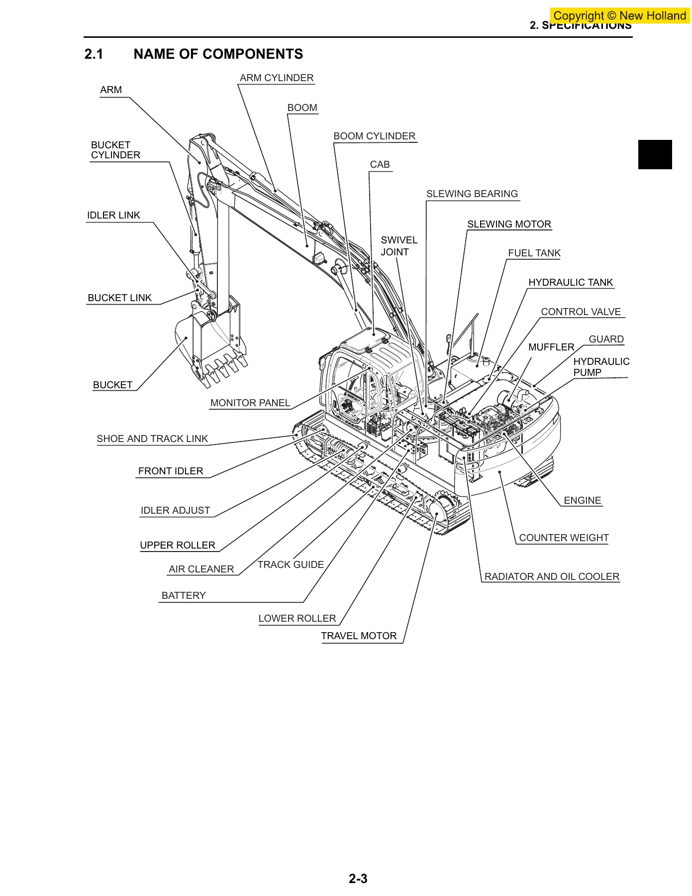
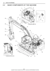
Chapter 2 lays out the full machine specifications for the E215B: engine data, hydraulic component details, swing and travel speeds, gradeability, weight distribution, transportation dimensions, and crawler shoe options. Chapter 3 provides the boom, arm, and bucket dimensional drawings with maintenance standards for pin and bushing clearances, plus the thrust-direction clearance specifications you need when rebuilding the front attachment. These chapters are essential for verifying that your machine is set up to factory specification before you begin any repair or adjustment work.
Tools and Maintenance Standards
Chapter 11 covers standard torque specifications for capscrews, nuts, hose fittings, plugs, and split flanges, along with special tools like the suction stopper, counterweight lifting jig, upper frame lifting jig, engine turnover stand, and track spring set jig. Chapter 12 gives the standard working time table for maintenance operations on the excavator, broken down by component group. Chapter 13 is the maintenance standard and test procedure chapter: it explains how to measure engine speed, hydraulic pressure, travel and swing performance, cylinder operating times, and mechatronic controller output. The A-B-C adjustment procedure for the mechatronic controller is covered in detail here, including what to do when the adjustment fails.
Mechatro Control System
Chapter 21 explains the mechatronic control system in full: unload valve control, positive control and P-Q control, boom up conflux, arm in recirculation and conflux, arm-in anti-cavitation, arm-out conflux, bucket digging conflux and anti-cavitation, swing priority, travel straight, travel independent, pressure release, N&B switch control, and option conflux. It also covers the multi-display, self-diagnosis display, service diagnosis, trouble history, trouble diagnosis mode, maintenance schedule setting, and display adjustment. This is the chapter you need when diagnosing electronic control issues or setting up the machine after controller replacement.
Hydraulic System
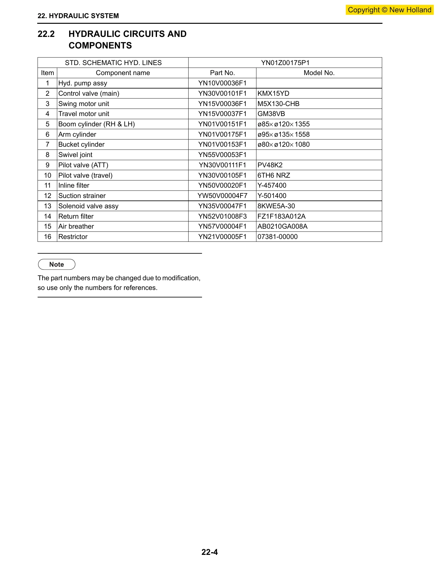
Chapter 22 covers the complete hydraulic circuit: neutral circuit, travel circuit, bucket circuit, boom circuit, swing circuit, arm circuit, combined circuits, and the pressure draining/releasing circuit. Color coding standards for hydraulic circuits are included, along with the hydraulic schematic lines and component part numbers. This chapter is indispensable for tracing oil flow, understanding combined operations, and diagnosing hydraulic faults.
Electrical System
Chapter 23 provides the electric circuit diagram, electrical equipment list, and complete harness information: instrument panel assembly, controller installation, tuner installation, upper electric assembly, upper harness assembly (including floor plate), cab harness assembly, boom harness assembly, and installation procedures for boom lights, upper lights, flasher lamps, and the travel alarm. This is your reference for electrical troubleshooting, harness repair, and accessory installation.
Components System
Chapter 24 is a deep dive into the major hydraulic and electrical components. It covers the hydraulic pump and regulator (construction, operation, adjustment, and troubleshooting), control valve (specifications, construction, operation, and maintenance standards), pilot valves for attachment and travel, swing motor unit, travel motor, swivel joint, and cylinders. The electric equipment section lists every sensor, solenoid, switch, relay, and controller with specifications. Each component section includes exploded views, part numbers, tightening torques, and operational explanations.
Air-Conditioner System
Chapter 25 covers the HVAC air-conditioner system: air cycle, auto air-conditioner system outline, component construction, piping, cooling circuit function, disassembly and assembly, refrigerant charging, electric circuit, troubleshooting, and the self-diagnosis function on the display panel. This chapter is complete enough to service the entire climate control system.
Disassembling and Assembling
Chapters 31 through 34 cover removal, installation, disassembly, and assembly of the machine’s major structures. Chapter 32 covers the attachment (bucket, arm, boom, and cylinder disassembly/assembly). Chapter 33 covers the upper structure: operator seat, cab, battery, guards, under covers, fuel tank, hydraulic tank, hydraulic pump, air cleaner, muffler, counterweight, radiator and oil cooler, engine, console cover, control valve, pilot valves, swing motor unit, swivel joint, and upper frame, plus disassembly and assembly of the hydraulic pump, regulator, control valve, pilot valves, swing motor, and swivel joint. Chapter 34 covers the travel system: crawler, upper roller, lower roller, front idler, sprocket, travel motor, and swing bearing. Each procedure includes weights, lifting points, tightening torques, and clearances.
Troubleshooting
Chapters 46, 47, and 48 provide comprehensive troubleshooting guidance. Chapter 46 covers troubleshooting by error code, including mechatronic controller blown fuse and every error code with its judging condition, symptom, control in the event of failure, and remedy. Chapter 47 covers troubleshooting by symptom, with detailed flowcharts for hydraulic system problems, electrical system problems, and engine-related issues. Chapter 48 covers troubleshooting by diagnosis mode, which automatically identifies failed systems for problems that cannot be detected by self-diagnosis.
Engine Section
Chapter 51 covers the CNH U.K. F4GE9684E (6.7 T/A) engine. It includes diagnostics (troubleshooting engine won’t start, engine overheats, engine lacks power, exhaust smoke, knocks, stops, excessive oil pressure or fuel consumption), engine overhaul procedures (disassembly, inspection, measurement, reassembly, valve timing, injection pump timing), and recharging/start-up (starter motor and alternator specifications and quick diagnosis). This section is essential for any engine repair or rebuild work.
Why This Manual Matters
When you are working on a New Holland E215B crawler excavator, guesswork is expensive. A wrong clearance on a boom pin, an incorrectly adjusted relief valve, or a misdiagnosed mechatronic fault can lead to damaged components, downtime, and costly returns. This service manual gives you the exact specifications, procedures, and diagnostic logic that New Holland engineers used to design and build the machine. It is the difference between a repair that lasts and a repair that comes back.
Whether you are resealing a hydraulic cylinder, rebuilding a travel motor, diagnosing a swing fault, adjusting the mechatronic controller, or overhauling the engine, the New Holland E215B Version C Service Manual is the reference you need on the bench. It covers the complete machine, from the attachment to the undercarriage, and from the hydraulic pump to the wiring harness.
IMAGES PREVIEW
Instant PDF Delivery
This manual is delivered as a high-quality PDF download immediately after purchase. No shipping, no waiting, no physical media to lose. You can view it on any device — laptop, tablet, or smartphone — and print the pages you need for the workshop. Whether you are in the field or in the shop, you have the full manual at your fingertips. The PDF format lets you zoom into detailed diagrams, search for specific values, and print reference pages to keep next to the machine. This is the complete, unabridged New Holland E215B Version C service and repair manual, covering Tier III models from S/N N7DA21001 with print number 87495894A.


Reviews
There are no reviews yet.