
New Holland L175 & C175 Skid Steer Loader Workshop Manual – 87630289 PDF Download
Original price was: $44.95.$29.95Current price is: $29.95.
Complete 967-page New Holland L175 and C175 skid steer workshop manual (document 87630289). Full engine, hydrostatic transmission, hydraulic, electrical, front loader and cab service coverage — instant PDF download.
Description
The New Holland L175 and C175 skid steer loaders share a common chassis and drivetrain family, and this Workshop Manual (document 87630289) is the complete service reference for both machines. Inside you get the full engine chapter, the hydrostatic transmission chapter, the hydraulic system chapter, the electrical chapter, plus the front loader, axle, frame, cab and climate sections that turn a running machine into a fully serviceable one. If you are repairing, overhauling or diagnosing an L175 or C175, this New Holland workshop manual PDF gives you the actual procedures the technicians use.
File Details
- Manual Type: Workshop / Repair Manual
- Brand: New Holland
- Models Covered: L175 (wheeled), C175 (tracked)
- Engine: N844LT diesel (turbocharged)
- Language: English
- Page Count: 967
- File Format: PDF
- Document Number: 87630289
Chapters Covered
- Section 00 — General Information
- Section 10 — Engine
- Section 27 — Tracks and Motors
- Section 29 — Hydrostatic Transmission
- Section 33 — Brakes and Controls
- Section 35 — Hydraulic System
- Section 37 — Towing Hooks and Ballasting
- Section 39 — Frames
- Section 44 — Axles and Wheels
- Section 50 — Cab Climate Control
- Section 55 — Electrical System
- Section 82 — Front Loader (Boom and Mounting Plate)
- Section 88 — Accessories
- Section 90 — Platforms, Cab, Bodywork, and Decals
Section 00 — General Information
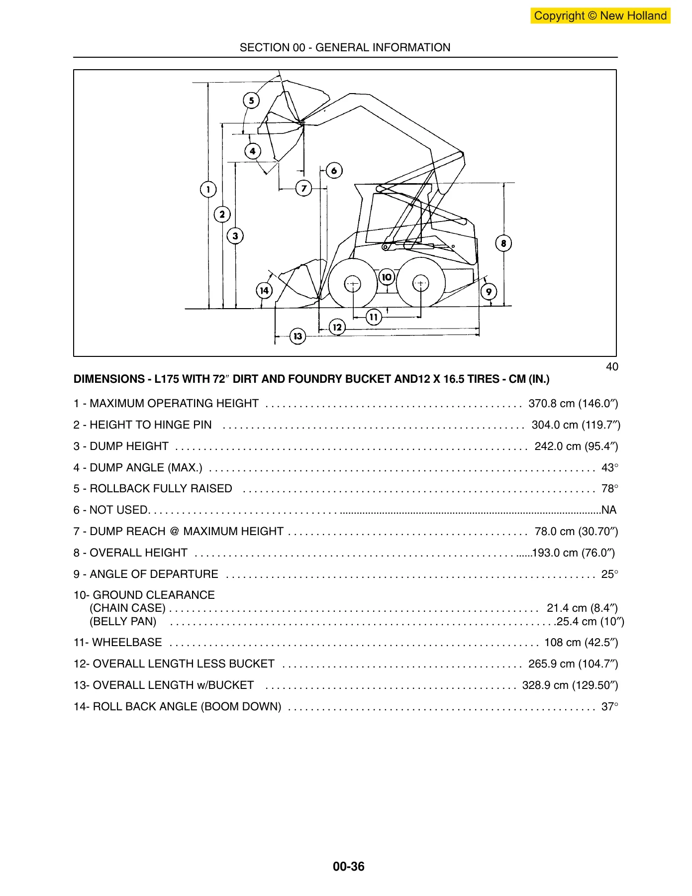
Everything you need before you open a panel: personal and machine safety statements, the exact locations of the machine and engine model/serial number tags, minimum hardware tightening torques in both inch and metric sizes, pipe thread fitting torques, lubricants and coolants with New Holland part numbers, sealant and thread-locker references, the correct way to support a raised machine, how to raise the boom when there is no hydraulic flow, and the craning procedure for the skid steer. The hardware torque charts alone will save you from rounded bolts and cracked castings across every job in this manual.
Section 10 — Engine
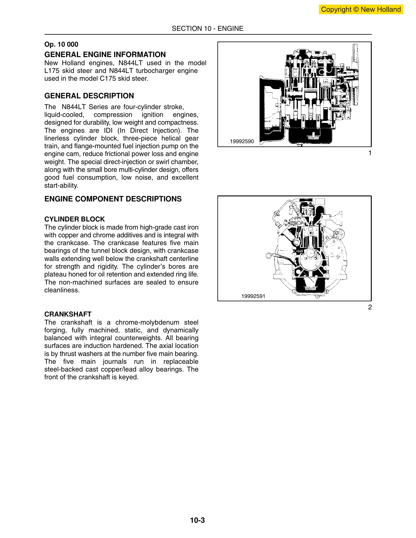
The full N844LT diesel engine chapter. General description, engine component identification, engine model and serial number location, turbocharger lubrication, safety precautions, general engine specifications, troubleshooting and an exhaustive excessive-oil-consumption diagnostic procedure. Removal is covered by two methods — with or without tilting the cab. The disassembly sequence walks through alternator, cooling fan and pulley, injector assembly, water pump, manifolds, rocker cover, external oil pipes, rocker assembly, cylinder head, tappets, stop solenoid, fuel injection pump, crank pulley, oil filter, gear cover and governor, idler gear and oil pump, camshaft, front end plate, dipstick, oil sump, suction pipe and strainer, connecting rod and piston, flywheel, backplate, crankshaft and main bearings. Reassembly, fuel injection timing, spill timing, governor operation, cooling system, fuel system, turbocharger service and special tools are all included.
Section 27 — Tracks and Motors
All rubber-track service for the C175. Wheel hub housing removal and installation, drive sprocket removal and installation with the star torque sequence, rubber track removal, installation and tension adjustment, the track tension mechanism, track roller service, front and rear idler wheel service, and the complete track drive motor disassembly and assembly including the two-speed control, flushing spool valve, flushing valve and base plate.
Section 29 — Hydrostatic Transmission
The chapter most owners will be reaching for. General operation, specifications, troubleshooting charts, the full hydrostatic drive system testing sequence — charge system pressure test, pump case drain test, pump high pressure test, pump efficiency test, motor case drain test, motor efficiency test and air ingress test. Then the teardown: hydrostatic pump removal, disassembly, parts inspection and reassembly, hydraulic system pump and high flow pump installation, motor removal, disassembly, parts inspection, reassembly, reinstallation, hydraulic system cleaning after a rebuild, charge check valve service, neutralizer assembly, hydrostatic control handle removal/rebuild and neutral adjustment. There is also a dedicated ISO pattern pilot control section covering pilot travel system operation and troubleshooting, DA pressure checks, charge pressure/flow checks, circuit relief valve checks, pump adjustments, pilot servo centering and travel lever removal/installation.
Section 33 — Brakes and Controls
Parking brake service on both L175 and C175 with removal, reinstallation, disassembly and reassembly procedures, plus troubleshooting for the parking brake button and the electrical solenoid, and illustrated brake valve and brake/two-speed valve references.
Section 35 — Hydraulic System
General information, hydraulic system compatibility rules for adapting attachments, boom cylinder pivot pin identification, control valve power-beyond port, specifications, troubleshooting, system testing, oil flow diagrams, main system pressure tests at boom and bucket cylinders and auxiliary quick couplers, boom circuit relief valve test, gear pump flow efficiency test, spool lock solenoid test and air ingress test. Then the teardown of control valve, hydraulic pump and high-flow pump, boom and bucket cylinders, pedal controls, oil cooler, filter base and oil reservoir. A dedicated pilot control section covers the loader control valve, implement controller, pilot pressure test and right control handle service.
Section 37 — Towing Hooks and Ballasting
Rear counterweight installation and the rear counterweight support removal procedure.
Section 39 — Frames
ROPS frame removal and reinstallation, including the full procedure for removing the ROPS with the cab inner shell and boom still attached — the electrically involved route that many shops avoid. Includes torque values for the front and rear ROPS hardware.
Section 44 — Axles and Wheels
General final drive information, specifications, troubleshooting, testing, axle housing removal, axle disassembly, parts inspection and reassembly, axle housing reinstallation, final drive drive chain and sprocket removal, final drive reassembly, drive chain tension adjustment, and tire/wheel specifications and installation notes including the hollow segmented tire and track compatibility guidance.
Section 50 — Cab Climate Control
Heater/defroster service on the cab — switch and control panel, heater core replacement, shutoff valve replacement, fan assembly replacement, heater hose routing and connections, filter replacement and L175 heater air bleeding. The air conditioning portion covers special tools, general specifications, system operation, discharging, evacuation and recovery, charging, compressor removal and installation, compressor oil level check, belt tension and adjustment, magnetic clutch disassembly and assembly, system removal and installation, condenser service, evaporator service, receiver/drier service, and the full A/C testing, leakage test and problem solving tables.
Section 55 — Electrical System
The largest single chapter after the engine. General electrical information, definition of terms, adapting attachments requiring 12V power, specifications, wire color identification, complete electrical diagrams for starting, power distribution, safety interlock and fuel supply, instrument cluster monitoring, standard lamps, loader arm auxiliary controls, flashers and turn signals, European on-road lighting, glow plugs, two-speed, horn, accessory outlet, back-up alarm, wiper/washer, auxiliary hydraulics, high flow, hydraulic coupler and pilot controls. Then the Electronic Instrument Cluster (EIC) and Advanced Instrument Cluster (AIC) operating instructions and troubleshooting, plus the removal/installation and wiring of every electrical component: battery, cab fuse block, seat switch, seat belt buckle, road/work light switch, engine fuse and relay panel, start interlock relay, preheat relay, glow plugs, fuel system components, electric fuel pump, fuel shutoff solenoid, air filter restriction switch, engine coolant temperature sender, engine oil pressure switch, hydrostatic charge pressure switch, hydraulic oil filter restriction switch, hydraulic oil temperature sender, boom/bucket spool lock solenoids, road/work lights, alternator (55 amp version) and starter.
Section 82 — Front Loader (Boom and Mounting Plate)
Bucket types and capacities, boom lock pins and linkage, the complete boom assembly, upper and lower link removal and reinstallation, boom and cylinder pivot pin identification, sizes and torques, attachment mounting plate removal and rebuild, latch lever and pin removal/repair, pallet fork and utility fork, cutting edge replacement welding procedure, bucket latch plate installation, dirt tooth kit installation and tooth spacing chart, and the checking procedure for buckets and attachments including faceplate measurement.
Section 88 — Accessories
Dealer-installed options: arm pads, armrests, forearm rests, back-up alarm, engine block heater, 12-volt electric power supply, exhaust options including catalytic and aspirator precleaner mufflers, high-flow hydraulics with troubleshooting and component replacement, horn, shoulder belt, slow-moving vehicle sign kit, rotary beacon and four-way flasher/turn signal/horn warning lights.
Section 90 — Platforms, Cab, Bodywork, and Decals
Seat and seat pan support removal and reinstallation, cab inner shell removal and reinstallation, and the safety decal list with part numbers and locations.
Why This New Holland L175 C175 Workshop Manual Belongs in Your Shop
A skid steer is a machine that earns its keep — and when it goes down, the cost is not just the repair, it is the downtime. This New Holland L175 C175 repair manual gives you the actual factory service procedures, the torque values, the pressure settings, the flow rates and the diagnostic sequences you need to get the machine back into production without guessing. You can service the N844LT engine from top to bottom, rebuild the hydrostatic pump and motor, test the charge system and case drain, overhaul the boom and bucket cylinders, chase electrical faults through the EIC or AIC harness, service the tracks or the final drive chains, and adjust the neutralizer and drive controls. Every procedure is written by the people who built the machine, with the warnings, the cautions, the tool numbers and the step-by-step sequences that keep the job safe and correct.
IMAGES PREVIEW
Delivered as an instant PDF download — no shipping, no waiting, no physical book to lose. Open it on a laptop, tablet or phone in the shop, print the pages you need for the job, and keep the full 967-page reference on hand for every future service. Whether you are a New Holland dealer technician, an independent shop, a municipality running a fleet, or an owner who does their own maintenance, this L175 and C175 skid steer workshop manual is the reference that pays for itself on the first repair.
Reviews
There are no reviews yet.