
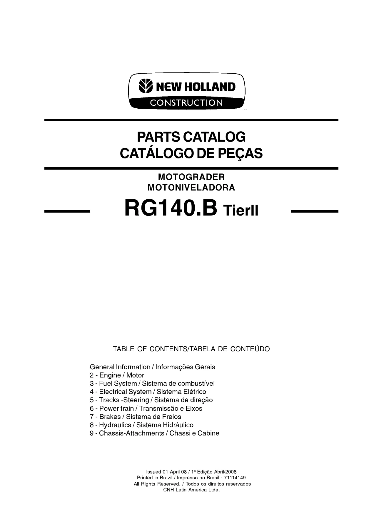
New Holland RG140.B Tier II Motograder Parts Catalog PDF – 71114149 Illustrated Parts Manual, April 2008
Original price was: $59.95.$39.95Current price is: $39.95.
Complete 623-page New Holland RG140.B Tier II motograder parts catalog (publication 71114149, first edition April 2008) with exploded assembly views, part numbers, quantities and bilingual English/Portuguese descriptions for engine, transmission, hydraulics, brakes, electrical and chassis components.
Description
New Holland RG140.B Tier II Motograder Parts Catalog – Publication 71114149
This is the full illustrated parts catalog for the New Holland RG140.B Tier II motograder, issued by CNH Latin America as publication 71114149 in April 2008. Across 623 pages it identifies every serviced component on the machine, from the engine and transmission supports through to the moldboard, scarifier, ripper and cab trim. Each figure page pairs an exploded illustration with a reference table giving the item number, part number, quantity, description and – where the catalog prints one – the year/serial introduction point for that part. Part descriptions appear in both English and Portuguese throughout, so the same document works at an English-speaking parts counter and in a Portuguese-language workshop. The Portuguese title page reads Catálogo de Peças – Motoniveladora RG140.B Tierll.
File Details
- Manual type: Illustrated parts catalog (bilingual English/Portuguese)
- Brand: New Holland
- Model: RG140.B Tier II motograder
- Publication number: 71114149
- Edition: First Edition, printed April 2008
- Languages: English and Portuguese
- Page count: 623
- File format: PDF
Chapters Covered
- General Information / Informações Gerais
- Engine / Motor
- Fuel System / Sistema de combustível
- Electrical System / Sistema Elétrico
- Tracks-Steering / Sistema de direção
- Power train / Transmissão e Eixos
- Brakes / Sistema de Freios
- Hydraulics / Sistema Hidráulico
- Chassis-Attachments / Chassi e Cabine
General Information
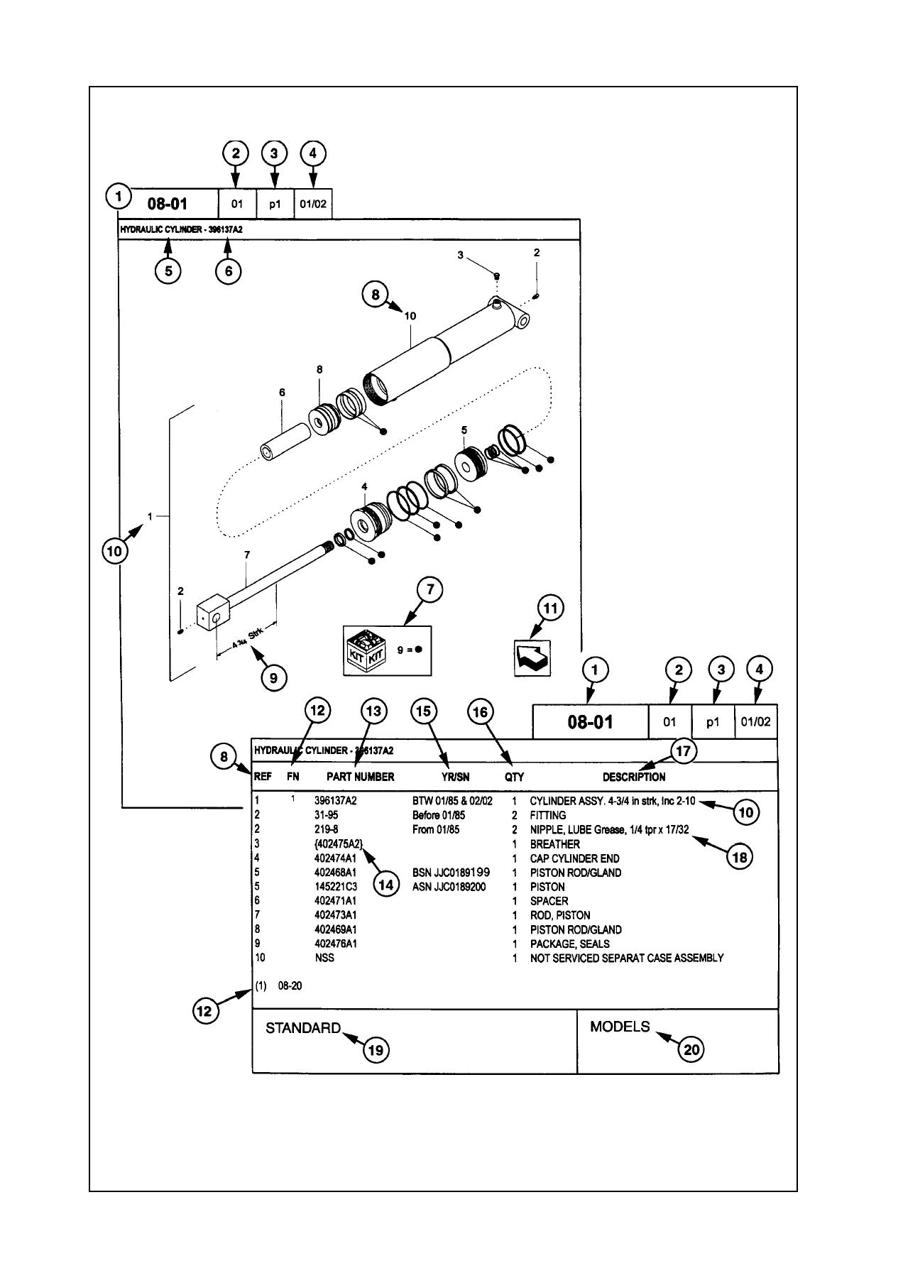
The opening pages explain how the catalog is built and how to read it: the figure numbering convention, the page-number sequence, the date of printing, the orientation arrow that shows which way the machine faces in each illustration, the meaning of NSS (not serviced separately) and of the quantity columns. Right-hand and left-hand sides are defined from the operator’s position, and the proprietary notice, company policy, genuine parts statement and spare-parts ordering information are reproduced in both languages – useful when you need to give a dealer the machine model, machine and engine serial numbers and the catalog part number in one correct order.
Engine (02-01 to 02-39)
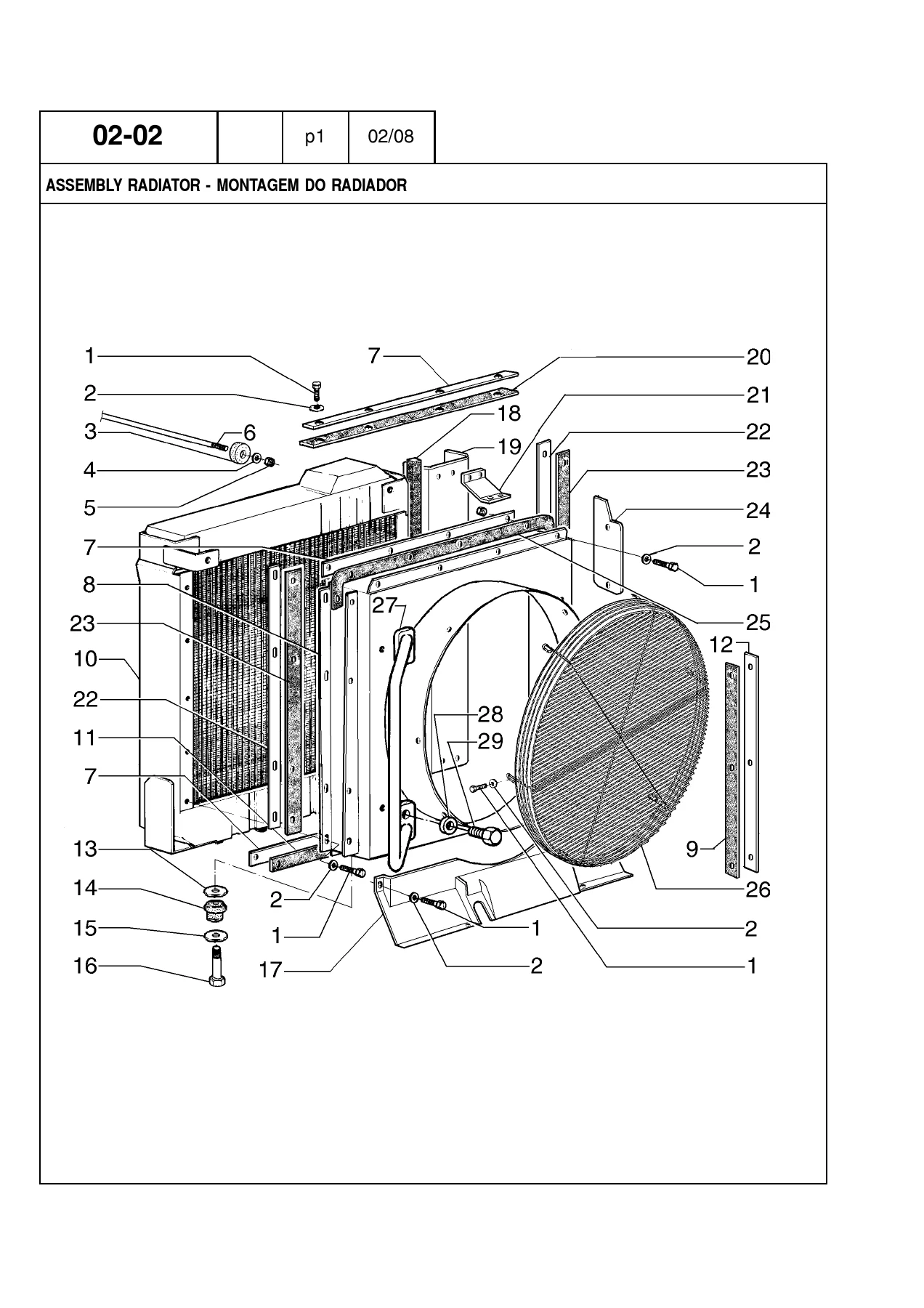
The largest mechanical group. It starts with the engine and transmission supports and the radiator assembly, then works through the engine oil cooler piping, transmission cooler, water tank, fan drive, fan drive reverser system and fan on-off system. Air cleaner and mounting, air cleaner elements and the muffler and exhaust pipe follow. The engine itself is broken down in detail: complete engine assembly, plugs and pins in the block, cylinder head and head cover, breather covers, oil level gauge and filler, oil sump, front gear cover, flywheel and crankcase covers, crankshaft and bushings, damper, connecting rods and pistons, valve gear, turbocharger and exhaust manifold, turbocharger lubrication, aftercooler, oil pump, oil filter and heat exchanger, water pump, thermostat valve, inlet water fitting, camshaft drive, pulleys and supports, and the belt tensioner and belt.
Fuel System (03-01 to 03-14)
Fuel lines, the fuel tank in two sections, throttle control linkage in two sections, the fuel injection pump, injection piping, nozzle holders, the fuel cut solenoid, the injection system, transfer pump and injection pump drive. The chapter closes with the fuel filter and the cold weather starting system, which is shown with its nozzle, cylinder, valve, relay, resistor and support hardware.
Electrical System (04-01 to 04-45)
Starter and starter assembly, 50A and 80A alternators with their supports and internal assemblies, batteries and harnesses, transmission harness, instrument panel and switches, cigarette lighter, transmission speed sensor, rear lights, lighting system, panel electrics, fuses and harnesses, main harness routing, scarifier and ripper electrics, the 24V/12V converter, back-up alarm, hydraulic accumulator electrics, engine electrics and reverser fan electrics. Lighting and cab hardware are covered in depth: headlight and lantern assemblies, cab front and rear lights, cab lower light, horn and support, wiper motors for front and rear screens, lower front wiper, washer pumps and reservoirs, cab and open-cab harnesses, air conditioner electrics, open cab fan, cab fan and the rotating warning beacons.
Steering and Operator’s Console (05-01 to 05-06)
Four console sections cover the steering column, hydraulic drive, control levers, knobs, bearings, ball joints and the linkage that connects them. The orbitrol unit is itemised down to its O-rings, impeller, shaft, discs, balls, springs and seal kits, and the steering cylinder is broken out with its head, rod, liner, piston and retainer seals.
Power Train (06-01 to 06-31)
Complete transmission assembly, PTO, speed shafts, and then each of the six shafts individually with their clutch discs, plates, bearings, snap rings, springs and plungers. Cases, valves, yoke, pump, oil cooler, dipstick, filter lines and oil filter are all listed. The chapter continues into the front axle, front axle reducter and wheel hub, the rear axle, rear axle housing, rear axle wheel hub assembly, the differential with its brake discs, planetary gears, spider and bevel gear set, and finally the rear axle tandem.
Brakes (07-01 to 07-11)
Parking brake and its control, control lever, brake control pedal group, and the brake hydraulic system across several pages with accumulators, connectors, hoses and switches. The brake booster valve and the brake/steering pump with its primary and secondary pump kits and seal kits complete the group.
Hydraulics (08-01 to 08-69)
The most heavily illustrated chapter. Hydraulic tank and filters, rear hydraulic system across several pages, moldboard side shift, circle shift, moldboard pitch, saddle lock pin cylinder and piping, moldboard lift piping, circle turn, scarifier and ripper piping, dozer blade float control, front wheel lean piping and articulation piping. Valve coverage includes relief, priority, solenoid, lock and retainer valves plus the main valve distributor block and each individual section valve. The main pump is broken into body and drum assemblies, and every cylinder is documented separately – front wheel lean, moldboard lift, moldboard pitch, saddle lock pin, circle shift, moldboard side shift, articulation, ripper lift and scarifier lift. Fan hydraulic motor, fan reversible hydraulic motor, hydraulic valve and reduction gear hydraulic motor close the chapter.
Chassis and Attachments (09-01 to 09-64)
Drawbar and circle, circle reduction gear, saddle and cylinders, rear main frame, front frame, articulation joint and cylinder, tow hook, battery supports, 12 ft and 13 ft moldboards with extensions and reinforcement, moldboard side shift and lean system, dozer blade and skid plates, scarifier and support, ripper tool bar and linkage, drawbar travel limiter, push plate, front counterweight and tool box. The cab section runs to more than thirty parts lists: fire extinguisher, driver’s seat, engine hood, console covers, guards and covers, sound suppressors, closed cab, cab mat and gaskets, air conditioner filters and ducts, inspection cover, cab glasses, low profile cab glasses, door, door covering, door and hinge, door sill and hook, rear-view mirror, both lock system sections, curtain, column covering, lower and rear coverings, roof coverings, open cab variants, air conditioner system, evaporator box and decals.
How Each Figure Page Works
Every illustration is keyed with call-out numbers that point straight at the table below it. The table columns give the reference number, the part number, the quantity required, the description in English and Portuguese, and the gloss code that identifies the part family. Where a part changed during production, the catalog prints the introduction point in the year/serial column so you can match the part to the machine in front of you rather than ordering by guesswork. Items marked NSS are not sold separately and must be ordered as part of the parent assembly, and kit references tell you when a seal or repair set is the correct purchase instead of individual O-rings.
Built for Real Parts Counter Work
Exploded views make it possible to identify a component by position rather than by description – the practical way to order a bracket, a spacer, a specific shim thickness or the correct end bit when two similar parts sit side by side. The hydraulic and cylinder sections are detailed enough to rebuild a leaking cylinder with the exact retainer, scraper and seal ring, and the transmission shaft pages let you pick the right clutch disc and snap ring for the shaft you are actually repairing. Because the catalog carries both languages on the same line, a bilingual workshop can hand the same page to the fitter and to the parts desk.
Get the Correct Part Number the First Time
IMAGES PREVIEW
Ordering a wrong part on a motograder costs a day of machine downtime, a return shipment and a second freight charge. This New Holland RG140.B Tier II parts catalog removes that risk by showing the assembly, the exact part number, the quantity and the serial break in one place, for every system on the machine. Use it to quote a repair, build a stock list for the workshop, verify a number a supplier has given you, or confirm that a superseded component still fits your serial number. The file is delivered as an instant PDF download after payment – no shipping, no waiting for a disc, no courier – and it opens on a laptop, tablet or phone in the workshop, on a desktop at the parts counter, or as a printed set of pages for the binder you keep in the service truck.

Reviews
There are no reviews yet.