
Nilfisk Advance CS7010 Sweeper Scrubber Service Manual PDF – Workshop Repair Guide
Original price was: $39.95.$24.95Current price is: $24.95.
Complete Nilfisk Advance CS7010 Sweeper Scrubber Service Manual in PDF – 329 pages covering engine, drive, steering, scrub, sweep, hopper, solution and recovery systems, plus full wiring diagrams, fault codes and shop measurements for every CS7010 model.
Description
File Details
- Manual Type: Service Manual
- Brand: Nilfisk / Nilfisk-Advance / Advance
- Model: CS7010
- Machine Type: Industrial Rider Sweeper/Scrubber
- Language: English
- Page Count: 329
- File Format: PDF
- Electrical Schematic Document Number: 56511580
- Wire Harness Diagram Document Number: 56511581
- Revision History: First Release 5/2017; updated 7/2017 (electrical schematic Rev B added); updated 11/2017 (firmware update procedure, KGST password correction, drive and steering error codes, steering shaft setscrew positioning)
Chapters Covered
- 03 – General Information: machine description, safety symbols, hopper prop rod, lifting, transporting, towing, diagnostic and service tools, technical specifications, torque specifications, maintenance schedule, lubrication points, EcoFlex system maintenance, PM checklist, machine controls, OLED display
- 04 – Control System: functional description, functional diagram, power modules, CAN Bus communication, component locations, main machine controller programming, Service Mode access, menu navigation, programming menu outline, hours menu, faults menu, service menu, output test, panel test, options menu, configuration menu, system menu, firmware update, fault codes for A1 Main Controller, A2 Power Module #1, A3 Power Module #2, A4 Drive Controller and A5 Steering Controller, device output dependencies, main machine controller removal and installation, shop measurements
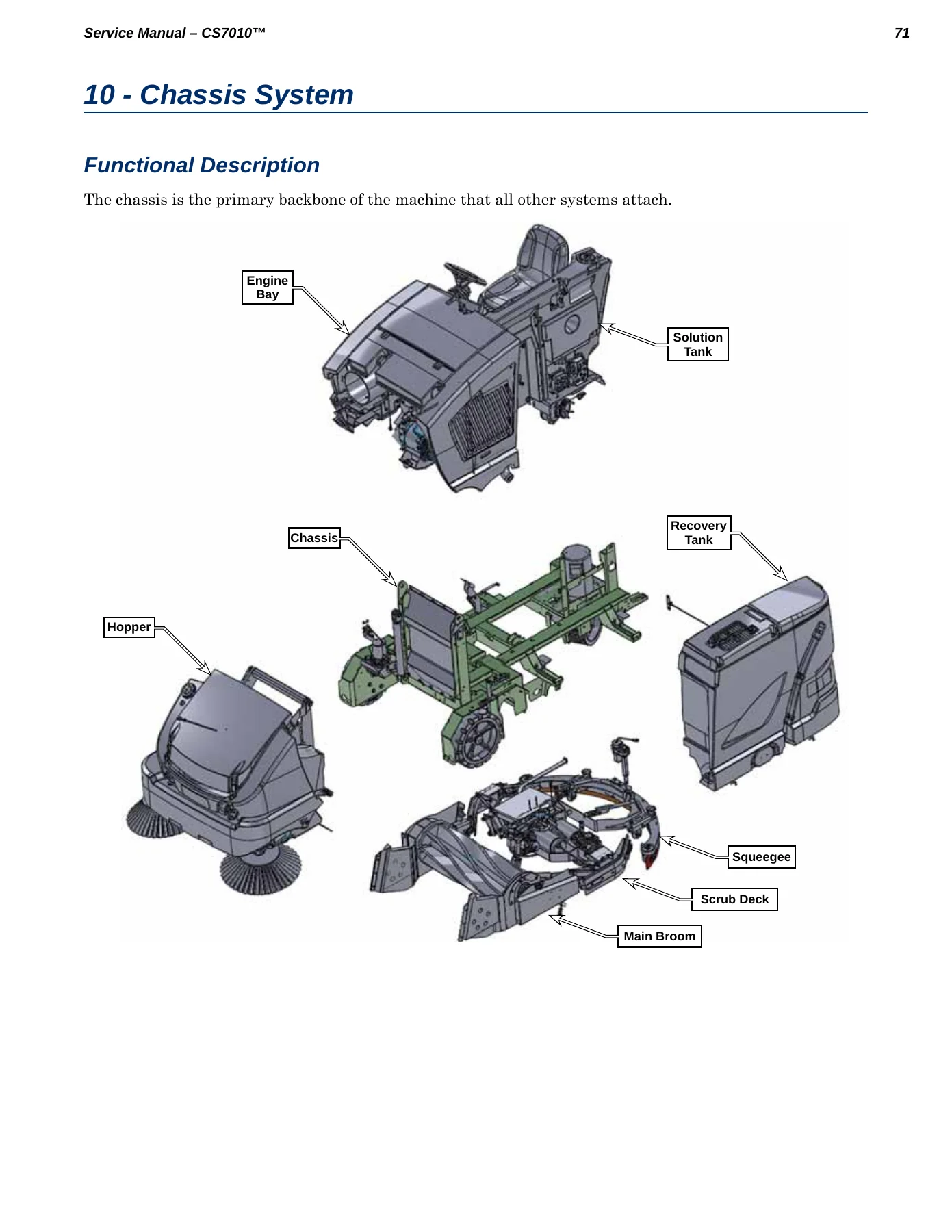
- 10 – Chassis System: functional description
- 14 – Wheel System, Non-Traction: functional description, maintenance and adjustments, brake adjustment, troubleshooting, wheel removal, wheel bearing, brake and spindle assembly
- 20 – Wheel System, Traction: functional description, drive motor, drive pedal potentiometer, drive controller, circuit description, powering up the drive controller, CAN Bus, component locations, gearbox oil, troubleshooting, fault codes, drive motor and gearbox assembly removal, drive wheel, drive controller, specifications, shop measurements, wheel drive K4 contactor
- 22 – Steering System: functional description, steering limit switches, steering motor, commutator resolver, steering position sensor and TFD, steering controller, functional diagram, component locations, troubleshooting, fault codes, symptom troubleshooting, steering wheel sensor and TFD removal, steering controller removal, steering actuator motor removal, specifications, shop measurements
- 24 – Electrical System: functional description, overview, wiring harnesses, circuit protection, un-switched power, switched power, prime power alternator (generator), lighting, low voltage cutout, component locations, battery interlock or interlock jumper, hybrid machine batteries, circuit protection and control, electrical panel layout, harness to harness connector locations, connector pin-outs, charging the battery, generator drive belt, troubleshooting, alternator-generator removal and installation, wiring diagrams (electrical schematic ladder diagram sheets 1-11, wiring harness diagram sheets 1-8)
- 28 – Engine System – LPG LEV: functional description, circuit descriptions, engine starter control, engine RPM control, normal engine shut off, engine protection modes, component locations, maintenance and adjustments, troubleshooting, engine management system, checking spark, checking LPG primary pressure, engine assembly removal and installation, specifications, fuel system, engine oil, engine coolant, shop measurements, special tools
- 28 – Engine System, Diesel: functional description, engine starter control, fuel pump control, engine protection, over temperature shutdown, low oil pressure shutdown, engine RPM control, glow plug control, component locations, maintenance and adjustments, diesel engine maintenance schedule, change engine oil and filter, change engine coolant, replace fuel filter, bleed fuel system, inspect air filter, replace air filters, troubleshooting, no crank, cranks but does not start, cannot achieve run or maximum engine speed, compression test, engine RPM sensor installation, engine assembly removal and installation, specifications, fuel pump, glow plugs, engine compression, engine oil capacity, engine oil type, engine oil viscosity, cooling system, engine coolant, radiator cap, shop measurements, special tools
- 28 – Engine System – Petrol (Gasoline): functional description, Kubota WG972-GL-E3-NFK-1 petrol engine, circuit descriptions, ignition system, engine starter and carburetor choke control, throttle control modes, ignition off, ignition on, cranking, normal running, engine RPM control, normal engine shut off, engine protection modes, engine overheat shutdown, lost oil pressure shutdown, component locations, maintenance and adjustments, maintenance checklist, change engine oil and filter, change engine coolant, inspect air filter, replace air filters, troubleshooting, checking spark, no crank, cranks but does not start, achieves one but not all RPM modes, engine RPM sensor installation, engine assembly removal and installation, specifications, engine oil, engine coolant, shop measurements, ignition system, spark controller measurements, governor control system, Woodward L Series actuator measurements, fuel system, engine, special tools
- 30 – Solution System: functional description, overview, solution flow control non-EcoFlex machines, solution flow control EcoFlex machines, EcoFlex detergent system, extended scrub system, optional hot water system, optional wash hose kit, optional high-pressure spray system, solution level sensor, solution system wiring diagram, circuit description, component locations, solution tank, drain hose, solution filter and solution shutoff valve, solution pressure sensor, solution pump, low pressure wash hose pump, solution solenoid valve, solution nozzles, EcoFlex detergent bottles and pumps, high-pressure spray system pump, extended scrub system, maintenance and adjustments, troubleshooting, solution tank removal, solution shutoff valve removal, solution filter assembly removal, solution solenoid valve removal, detergent pump removal, specifications, special tools
- 34 – Scrub System: functional description, overview, scrub system wiring diagram, circuit description, scrub deck actuator motor, component locations, scrub motor assemblies, right swingarm, side squeegee assemblies, scrub deck actuator, maintenance and adjustments, replace a leading deck blade, replace a trailing deck blade, side squeegee assembly removal, scrub deck actuator removal, actuator adjustment, scrub deck removal, scrub motor removal, scrub motor carbon brushes, specifications, special tools
- 38 – Squeegee System: functional description, overview, squeegee and recovery wiring diagram, component locations, maintenance and adjustments, changing squeegee blades, squeegee end wheels, squeegee caster wheel bearings, squeegee tilt adjustment, squeegee casters adjustment, troubleshooting, squeegee lift actuator removal, actuator adjustment, squeegee support assembly removal, squeegee lift arm removal, specifications, special tools
- 40 – Recovery System: functional description, overview, recovery and squeegee wiring diagram, component locations, recovery tank, recovery tank cover and debris basket, vacuum fan cover assembly, vacuum motors, float cage and ball assemblies, maintenance and adjustments, clean the vacuum filter and filter screen, clean the debris basket, troubleshooting, recovery tank removal, vacuum motor removal, specifications, special tools
- 42 – Sweep System, Main: functional description, overview, sweep system wiring diagram, circuit description, main broom actuator, main broom motor, component locations, main broom and drive components, maintenance and adjustments, adjust the main broom height, adjust the main broom tilt, main broom removal, broom motor removal, main broom motor carbon brushes, broom lift actuator removal, specifications
- 48 – Sweep System, Side Broom: functional description, overview, side broom and main broom wiring diagram, component locations, side brooms, side broom motors, side broom actuator, maintenance and adjustments, replacing a side broom, side broom motor carbon brushes, side broom motor removal, side broom hub removal, specifications, special tools
- 50 – Dust Control/DustGuard Systems: functional description, overview, dust control system, DustGuard spray system, dust control and hopper wiring diagram, component locations, impeller and filter system, dust control filter switch, DustGuard spray system, maintenance and adjustments, clean the dust control filter, clean the DustGuard strainer screen, clean the DustGuard spray nozzles, adjust the DustGuard spray nozzles, troubleshooting, DustGuard solenoid valve removal, dust control filter switch removal, DustGuard pump removal, impeller assembly removal, specifications
- 52 – Hopper System: functional description, overview, hopper and dust control wiring diagram, component locations, upper and lower hopper, hydraulic power pack assembly, hopper dump door, hopper dump door actuator, dump door limit switch, hopper interlock switch, hopper prop rod and pull rod, maintenance and adjustment, hydraulic oil change/flush, dump door actuator adjustment, hydraulic power pack assembly removal (LPG/diesel and battery models), hopper lift cylinder removal, hopper interlock switch removal, hopper dump door actuator removal, specifications
- 90 – Options and Accessories: seat belt kit, recovery tank clean out kit, back-up alarm kit, fire extinguisher kit, LED brake light/turn signal kit, rear corner roller kit, hopper temperature sensor kit, plugged filter switch kit, high pressure pump kit, front corner roller kit, extended scrub kit, EcoFlex chemical injection kit, overhead guard kits, deluxe seat kit, hot water scrub kit, squeegee guard kit, front bumper kit, super duty kit, spray wash hose kit, overhead guard beacon kit, warning beacon kit, solution fill shut-off kit, vacuum wand kit, accessory socket kit, drain hose extension, arm rest option
The Nilfisk Advance CS7010 Sweeper Scrubber Service Manual PDF is the complete workshop reference for maintaining, repairing and diagnosing every variant of this industrial rider sweeper/scrubber. Across 329 pages it walks a technician through the full machine – from the Kubota engine and 42V alternator-generator down to the scrub brushes, squeegee blades, main broom carbon brushes and hopper hydraulic cylinder. Every system chapter opens with a functional description and a dedicated wiring diagram, then moves into component locations, maintenance intervals, troubleshooting trees, removal and installation procedures, and real shop measurements taken from a running machine. If you service, own or fleet-manage a CS7010, this Nilfisk CS7010 workshop manual gives you the exact torque values, fault-code tables, connector pin-outs and adjustment dimensions the machine was built to.
What the CS7010 Service Manual Covers in Detail
The Nilfisk CS7010 repair guide is organised the way a technician actually works – system by system, with the diagnostic layer treated as a first-class part of every chapter. The Control System chapter alone spans more than thirty pages of fault-code tables for the A1 Main Controller, A2 and A3 Power Modules, A4 Drive Controller and A5 Steering Controller, including the exact amperage thresholds, voltage conditions and probable causes behind every 4-digit error code the machine can display. That single section turns a vague dashboard warning into a specific test with a known-good voltage to compare against.
Electrical and Wiring Diagram Coverage
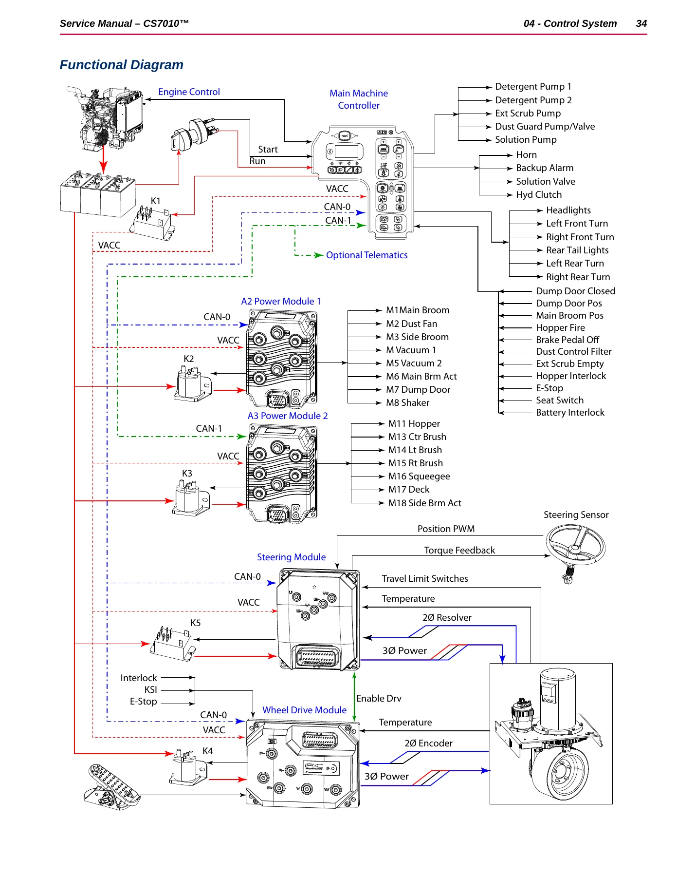
The electrical section includes the full ladder-diagram schematic split across eleven sheets – main controller, both power modules, drive controller, steering controller, Kubota diesel, Kubota gasoline, Kubota LEV and Trackclean connections – plus eight harness diagram sheets covering the main harness, hopper harness, LEV engine interface, glow plug/vacuum/tail light, engine battery and generator harness, and Trackclean harness. Connector pin-outs are tabulated for every multi-cavity plug on the machine, and harness-to-harness connector locations are photographed so you can find X42/X43, X112/X113, X99, X45 and the Trackclean jumper without guessing. For intermittent electrical faults, the CAN Bus communication description explains the twisted-pair signalling, dominant/recessive bits and the 120-ohm termination so you can diagnose a bus-off condition correctly rather than replacing parts.
Engine Coverage Across All CS7010 Variants
Three separate engine chapters cover the CS7010’s engine options: the Kubota WG972-E4 LPG LEV, the Kubota D1305-E3B-KEA-1 diesel, and the Kubota WG972-GL-E3-NFK-1 petrol/gasoline engine. Each chapter documents the starting circuit, RPM control modes (idle, run, maximum power), glow plug or choke operation, engine protection shutdowns for over-temperature and lost oil pressure, and the exact ECU or governor-controller wire states that request each speed. The diesel chapter includes a full bleed procedure, compression test with an adapter through the glow plug threads, engine RPM sensor air-gap setting and the APECS 3000 governor flash-code table. The LPG LEV chapter includes the KGST diagnostic tool password, LPG primary pressure test, and COP ignition spark check. The petrol chapter includes ignition coil primary and secondary resistance, crank position sensor output waveform, and Woodward L-Series actuator pin-by-pin voltages.
Drive, Steering and Brake Systems
The traction wheel chapter covers the InMotion AC Superdrive controller, the remotely commutated three-phase drive motor with internal encoders, the wig-wag drive pedal potentiometer and its neutral deadband, gearbox oil type and capacity, and the shop-measured K4 contactor winding resistance. The steering system chapter explains the steer-by-wire architecture, the resolver-based commutation, the MagnetoRheological TFD torque feedback device, limit switch testing with an ohm meter, and the exact steering controller pin voltages under normal and limit-stop conditions. The non-traction wheel chapter documents the drum brake shoe adjustment via the clevis yoke – critical for keeping left and right brakes balanced so the machine stops straight.
Scrub, Sweep, Squeegee, Recovery and Hopper Systems
Every cleaning system has its own removal-and-installation sequence with torque values and polarity notes: scrub deck actuator adjustment to 12.50 inches between mounting holes, squeegee actuator adjustment to 12.07 inches, scrub motor carbon brush replacement with wave washer orientation, main broom sweep pattern width of 2 to 3 inches, side broom motor carbon brushes, and the full hydraulic oil flush procedure for the hopper lift cylinder including the velocity fuse reset. The dust control and DustGuard chapters cover filter cleaning, spray nozzle orientation, strainer service and the plugged-filter switch setting. The hopper chapter even documents the dump door actuator potentiometer synchronisation to 0.60 volts and the door open voltage configuration.
Your Complete Nilfisk CS7010 Workshop Repair Guide
Whether you are replacing a vacuum motor, chasing a 4-227 Drive Enable Open code, setting the main broom tilt so the sweep pattern is even end to end, or flushing the hopper hydraulics after a cylinder reseal, this Nilfisk Advance CS7010 Sweeper Scrubber Service Manual PDF puts the procedure, the specification and the diagnostic path in one place. It covers CS7010 48G, CS7010 48LP, CS7010 48LP LEV, CS7010 48D and CS7010 48B battery models, so a single document serves an entire mixed fleet. Using the correct torque, adjustment dimension and fault-code threshold is the difference between a repair that lasts and a comeback – and the shop measurements scattered through every chapter give you a real-world voltage or resistance to compare against when the book’s nominal spec and the machine in front of you disagree.
Delivery is instant: the PDF is available immediately after payment, with no shipping and no waiting on a disc. It opens on any laptop, tablet or phone, and pages can be printed for the workshop bench – useful for the long procedures like the hydraulic flush or the main broom motor carbon brush replacement. Keep a copy on the service laptop and another on the shop printer, and you have the CS7010’s full service documentation ready whenever a machine comes in.
IMAGES PREVIEW
Reviews
There are no reviews yet.