
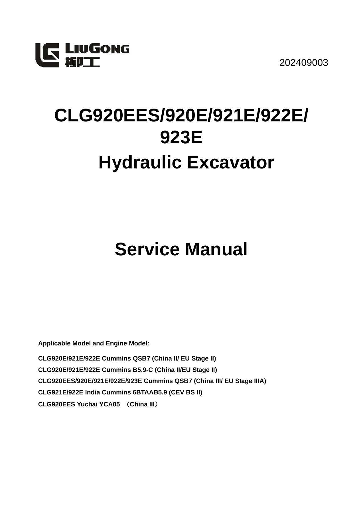

LiuGong CLG920EES 920E 921E 922E 923E Hydraulic Excavator Service Manual – 2024 Complete Workshop Guide
Original price was: $39.95.$23.95Current price is: $23.95.
Complete LiuGong CLG920EES/920E/921E/922E/923E hydraulic excavator service manual (Doc 202409003, Sept 2024). Covers Cummins QSB7, B5.9-C, India Cummins B5.9, and Yuchai YCA05 engines. Includes full DTC diagnostics, hydraulic system overhaul, removal/installation procedures, torque specs, and electrical schematics. Instant PDF download.
Description
LiuGong CLG920EES/920E/921E/922E/923E Hydraulic Excavator Service Manual
Complete Workshop Reference for Professional Technicians, Fleet Maintenance Teams, and Equipment Owners
File Details
- Manual Type: Service Manual (Workshop Guide)
- Brand: LiuGong
- Models Covered: CLG920EES, CLG920E, CLG921E, CLG922E, CLG923E
- Document Number: 202409003
- Publication Date: September 2, 2024
- Language: English
- File Format: PDF
- Page Count: Approximately 1,278 pages
Chapters Covered
- 1. Safety — Safety Precautions, Compressed Air, High-Pressure Solution, Safe Disposal of Waste Liquid, Accumulator Application, Asbestos, Prevent Crushing or Cutting, Prevent Burn, Coolant, Oil, Battery, Fire and Explosion Guides, Diethyl Ether, Pipeline Pipe and Hose, Fire Extinguisher and First-Aid Kit, Preventing Thunder, Cab Protector, Measures in Emergencies, Inner Space of Cab, Accessories, Lifting and Collaborative Operations, Mobile and Bridge Crane Operation, Cable Selection
- 2. Foreword — How to Read the Manual, Marking of Revised Version, General Torque Specifications, Unit Conversion Table, Cable Identification Methods, Coating Materials, Weight Table, Specifications for Oil Application
- 3. Structural Function and Maintenance — Power System, Track Travel System, Hydraulic System (Main Pump, Main Control Valve, Center Connector, Explosion-Proof Valve, Hand Pilot Valve, Travel Pilot Valve, Cushion Valve, Solenoid Valve, Travel Motor & Speed Reducer, Slewing Motor & Speed Reducer, Cylinder, Hydraulic Tank), Work Implement, A/C System, Electrical System
- 4. Parameters — Basic Parameters, Performance Parameters of Diesel Engine, Performance Parameters of Complete Machine
- 5. Test and Adjustment — Performance Test of Complete Machine, Diesel Engine Speed, Travel Speed, Driving Speed, Travel Deviation, Slewing Service Brake Angle, Slewing Speed, Slewing Bearing Clearance, Action Time of Cylinder, Cylinder Settlement, Operating Force of Control Lever, Control Lever Stroke, Boom Lifting and Slewing Action, Pilot Pressure, Secondary Pilot Pressure, Output Pressure of Solenoid Proportional Valve, Setting Pressure of Main Relief Valve, Other Tests including Valve Lash Adjustment, Crankcase Blow-By Measurement, Oil Pressure Measurement, Track Tension Adjustment, Negative Feedback Pressure N1/N2 Inspection, Residual Pressure Release, Air Bleeding, Diode Inspection, Compressor Belt Tensioner Adjustment, Travel Motor Performance Test
- 6. Fault Diagnosis — Precautions for Fault Diagnosis, Basic Fault Detection Before Maintenance, Classification of Faults, Diagnostic Trouble Code (DTC) coverage for battery voltage, engine speed sensor, coolant temperature, hydraulic oil temperature, fuel level, water-in-fuel sensor, pump proportional solenoid, travel speed solenoid, flattening solenoid, trenching solenoid, flow adjusting solenoid, power boosting solenoid, travel lifting solenoid, battery relay, preheating relay, start cut-off relay, travel alarm, pump pressure sensors, negative flow pressure sensors, actuator feedback, CAN bus, GPS, fan reversing and drive solenoids; Fault Diagnosis of Electrical System (E1–E23) including battery power loss, automatic slowdown, engine start/shutdown, preheater, display panel, hydraulic oil temperature display, fuel gauge, windshield wiper, travel alarm, A/C panel, A/C no air or abnormal volume, poor A/C refrigeration, defrost sensor, solar sensor, external air sensor, air blowing valve, air mixing valve; Fault Diagnosis of Hydraulic and Mechanical Systems (H1–H13) including slewing brake angle, pump mounting noise, unresponsive operations, hydraulic oil emulsification, oil temperature rise, slewing and travel faults, slow or weak boom/arm/bucket action, engine speed reduction or stalling
- 7. Removal and Installation — Power System (Diesel Engine Assembly, Hydraulic Oil Radiator, Intercooler, Water Radiator, Fuel Tank Assembly, Injector, Engine Front Seal, Engine Rear Seal, Cylinder Head Assembly, Fuel Cooler), Track Travel System (Track Roller, Carrier Roller, Track Assembly, Sprocket, Idler Assembly and Tensioner Assembly, Revolving Frame, Slewing Bearing), Covering Parts (Engine Hood, Counterweight), Hydraulic System (Center Joint Assembly, Hydraulic Oil Tank, Main Control Valve Assembly, Main Pump Assembly, Travel Pilot Valve Assembly, Hand Pilot Valve Assembly, Travel Motor & Speed Reducer, Slewing Motor & Speed Reducer), Work Implement (Bucket, Link and Lever, Arm, Boom, Work Implement Assembly, Bucket Cylinder, Arm Cylinder, Boom Cylinder, Cylinder Disassembly and Assembly), A/C System (Compressor Assembly, Evaporator Assembly), Cab and Floor Frame Assembly
- 8. Attached Drawing — Hydraulic Schematic Diagram (Kawasaki and Rexroth systems), Schematic Diagram of Electric System (CM3620 and C101-D1 controllers), Schematic Diagram of A/C System
This service manual provides the complete technical foundation for maintaining LiuGong CLG920EES, 920E, 921E, 922E, and 923E excavators. It combines structural function explanations with practical maintenance standards, giving technicians a single reference that spans from routine inspections to component-level overhaul procedures. The document is organized to follow the actual workflow of a service technician: understand the system, check the specifications, test and adjust, diagnose faults, and remove and install components correctly.
Model and Engine Coverage
The manual addresses the following model and engine combinations with dedicated specifications for each:
- CLG920E/921E/922E — Cummins QSB7 (China II / EU Stage II)
- CLG920E/921E/922E — Cummins B5.9-C (China II / EU Stage II)
- CLG920EES/920E/921E/922E/923E — Cummins QSB7 (China III / EU Stage IIIA)
- CLG921E/922E India — Cummins 6BTAAB5.9 (CEV BS II)
- CLG920EES — Yuchai YCA05 (China III)
Whether servicing a Cummins QSB7-powered excavator in China III configuration or a Yuchai-powered CLG920EES, the manual provides engine-specific performance parameters, oil specifications, valve clearance data, and maintenance intervals for each variant. The engine chapters cover the Cummins QSB7, Cummins B5.9-C, India Cummins B5.9, and Yuchai YCA05, with detailed specifications for bore, stroke, displacement, compression ratio, firing order, rated power, maximum torque, oil capacity, oil pressure, fan configuration, starter motor, alternator, and valve clearance.
Fault Diagnosis and DTC Coverage
One of the strongest sections of this manual is its fault diagnosis chapter. It includes detailed Diagnostic Trouble Code (DTC) procedures covering a wide range of electrical and hydraulic system faults. Each DTC entry provides a system description, consequences, component location, and step-by-step troubleshooting with expected resistance and voltage values. The DTC coverage includes:
- Battery and charging: DTC 101001 extremely low battery voltage, DTC 101003 high battery voltage, DTC 101017 low battery voltage, DTC 111001 system charging fault
- Engine sensors and switches: DTC 121015 oil pressure switch disconnected, DTC 121018 low oil pressure, DTC 121305 handle pressure switch OFF, DTC 121405 pedal pressure switch disconnected, DTC 131000 high engine speed, DTC 131005 engine speed sensor fault
- Temperature sensors: DTC 131100, 131103, 131104, 131115, 131116 for coolant temperature; DTC 131203, 131204, 131215, 131216 for hydraulic oil temperature
- Fuel and water sensors: DTC 131303, 131304, 131317 for fuel level; DTC 131603, 131604, 131605, 131615 for water-in-fuel
- Solenoid valves: Pump proportional solenoid (141005, 141006, 141104, 141105), attachment confluence (151004, 151005), travel speed (151204, 151205), flattening (151304, 151305), trenching (151404, 151405), flow adjusting (151504, 151505, 151605), power boosting (151704, 151705), travel lifting (151804, 151805)
- Relays: Battery relay (171004), auto preheating relay (171104, 171105), start cut-off relay (171204, 171205)
- Alarms and horns: Travel alarm (201004)
- Pressure sensors: P1 pump pressure (211003, 211004), P2 pump pressure (211103, 211104), N1 negative flow (211203, 211204), N2 negative flow (211303, 211304, 211316), pump pressure-reducing valve (211404)
- Actuator feedback: Voltage below/above range (221001, 221003), getting stuck (221007), outside calibrated range (221013), AC1/AC2 short to ground (221104, 221204), open circuit (221305, 221405), overcurrent (221306, 221406)
- Communication and GPS: Controller heartbeat (231012), CAN bus (231014), accelerator knob (241014), fuel pump relay (251004, 251005), GPS antenna/module/GSM/GPRS/SIM (261011, 261111, 261211, 261311, 261411), GPS heartbeat (261512), locking levels (261611, 261614, 261711, 261714, 261814)
- Fan control: Fan reversing solenoid (271304, 271305), fan drive solenoid (271404, 271405, 271505)
The electrical system fault diagnosis section (E1 through E23) addresses practical troubleshooting for issues like battery power loss, abnormal battery, automatic slowdown failure, engine cannot be started, engine shuts down during operation, engine cannot be shut down, preheater not working, all work implements/revolving/traveling cannot move, display panel showing nothing, incorrectly displayed hydraulic oil temperature, fuel gauge cannot display correctly, windshield wiper out of work, travel alarm unable to sound, A/C panel unable to display, no air or abnormal air volume, poor A/C refrigeration, and various A/C sensor and valve alarms.
The hydraulic and mechanical system fault diagnosis section (H1 through H13) covers problems such as excessive braking angle for slewing stop, abnormal noise from pump mounting position, engine starts but all operations have no response, hydraulic oil emulsification, abnormal increase of hydraulic oil temperature, slewing abnormally to left and right directions, no response for slewing single direction operation, slewing cannot be stopped, fail to actuate unilateral travel mechanism, travel deviation, slow speed of the boom/arm/bucket, weak actions of the boom/arm/bucket, and significantly reduced engine speed or engine stalling.
Hydraulic System and Component Overhaul
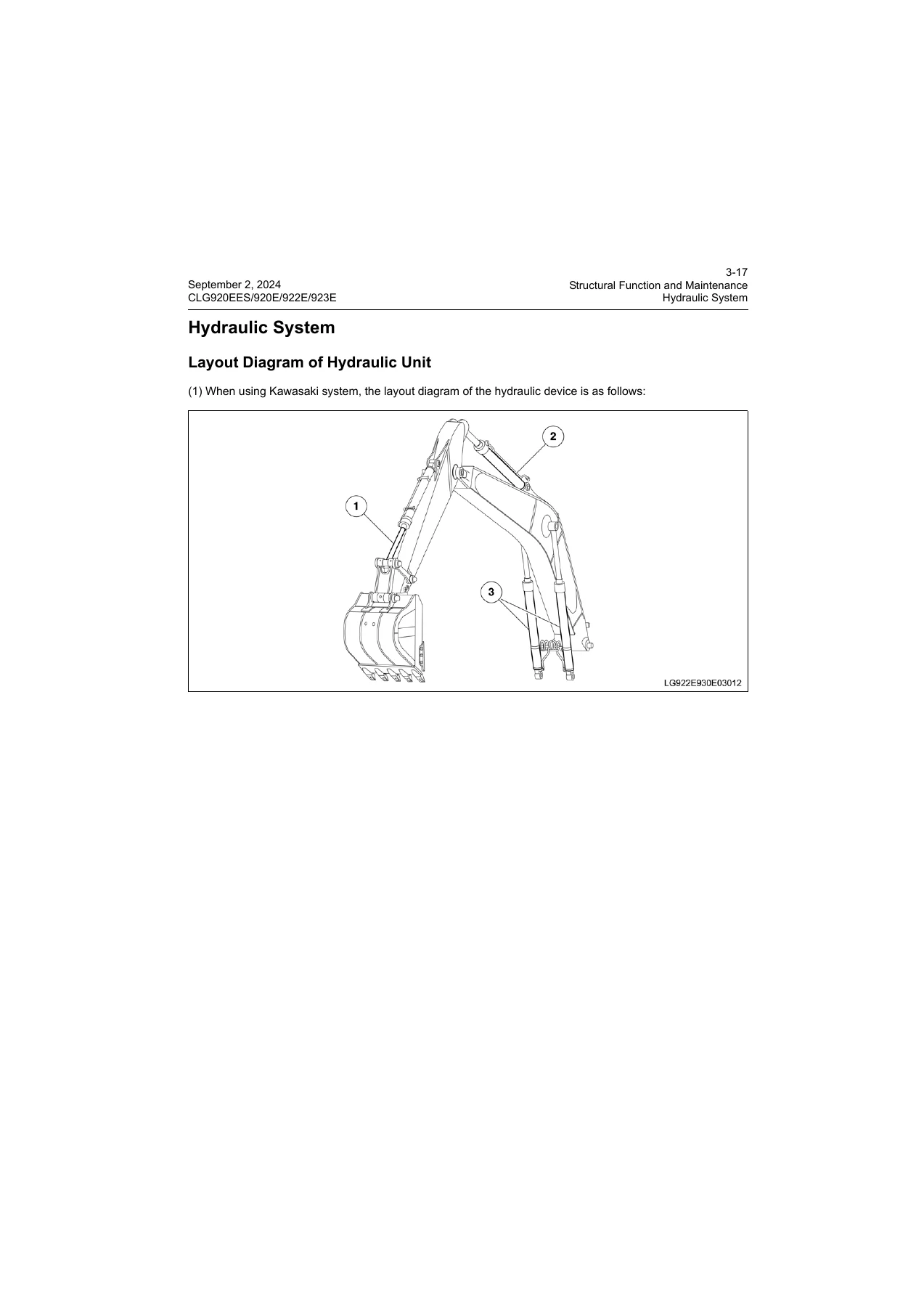
The hydraulic system chapter provides detailed coverage of the main pump assembly (both Kawasaki and Rexroth configurations), main control valve, center joint, explosion-proof valve, hand pilot valve, travel pilot valve, cushion valve, solenoid valve, travel motor and speed reducer, slewing motor and speed reducer, cylinders, and the hydraulic tank. The removal and installation section walks through component removal procedures with tightening torques, special tool references, and assembly precautions. The manual includes detailed exploded views and cross-section diagrams for major components, making it suitable for hydraulic component overhaul work.
For the Kawasaki system, the manual documents the KMX15RB main control valve with its specifications, port dimensions, and hydraulic circuit diagrams. For the Rexroth system, it covers the M9-G1118-00/7M9-25 control valve. Both systems are treated separately where their procedures and specifications differ. The main pump section includes the Kawasaki main pump with a displacement of 116.5 cm³/rev × 2 and the Rexroth main pump with a displacement of 130 cm³/rev × 2, along with their respective pilot pump specifications and control mechanisms including power control, power switching control, and flow control.
Test and Adjustment Procedures
The test and adjustment chapter provides the measurement methods and standard values needed to verify machine performance after repair or during routine inspections. This includes diesel engine speed tables for P and E modes, travel speed measurements, travel deviation testing, slewing brake angle and speed, slewing bearing clearance, hydraulic cylinder action times, cylinder settlement limits, control lever operating forces and stroke, pilot pressures, main relief valve setting pressure, and solenoid proportional valve output pressures. The manual also covers valve lash adjustment, crankcase blow-by measurement, engine oil pressure measurement, track tension adjustment, negative feedback pressure inspection, and air bleeding procedures.
Standard values are provided for engine speeds across all 12 gear positions in both P and E modes, travel speeds in tortoise and rabbit positions, slewing speeds, cylinder action times, control lever operating forces, pilot pressures, main circuit pressures, and port relief valve pressures. The manual includes attached tables for recording test measurements, making it practical for field and workshop use.
Removal and Installation Procedures
The removal and installation chapter is one of the most extensive sections, covering the complete disassembly and assembly of major components. It begins with the power system, detailing the removal and installation of the diesel engine assembly, hydraulic oil radiator, intercooler, water radiator, fuel tank assembly, injector, engine front and rear seals, cylinder head assembly, and fuel cooler. The track travel system section covers track rollers, carrier rollers, track assemblies, sprockets, idler and tensioner assemblies, the revolving frame, and the slewing bearing. The hydraulic system section covers the center joint, hydraulic oil tank, main control valve, main pump, travel pilot valve, hand pilot valve, travel motor and speed reducer, and slewing motor and speed reducer. The work implement section covers the bucket, link and lever, arm, boom, work implement assembly, and all three cylinder assemblies with detailed disassembly and assembly instructions.
Who This Service Manual Is For
This manual is written for professional diesel and hydraulic technicians, fleet maintenance managers, and equipment owners who need to perform diagnostics, repairs, and overhauls on LiuGong CLG920EES, 920E, 921E, 922E, and 923E excavators. It is also suitable for technical schools and training centers that teach heavy equipment repair. The level of detail—from DTC troubleshooting to component-level disassembly with torque specifications—makes it useful for both experienced technicians and those new to these specific machines who need a reliable reference.
Why This LiuGong Excavator Service Manual Matters
Whether you’re performing scheduled maintenance, diagnosing an electrical fault code, overhauling a hydraulic pump, or replacing a final drive, this manual provides the specifications and procedures needed to do the job correctly. The combination of DTC diagnostics, hydraulic schematics, torque values, and component removal sequences means you can move from symptom to repair without guesswork. The manual covers multiple engine variants and two hydraulic system configurations, so it remains useful across a fleet of different LiuGong excavator models. The instant PDF delivery means you can have the manual on your computer, tablet, or phone within minutes of purchase and start working on the machine the same day. The document is printable, so you can bring the relevant pages directly to the machine without risking your device in the workshop.

Reviews
There are no reviews yet.