
JLG 600S 600SJ 660SJ 600A 600AJ Service and Maintenance Manual – 2005 PDF
Original price was: $39.95.$23.95Current price is: $23.95.
Complete JLG Service and Maintenance Manual (P/N 3120718) for 600S, 600SJ, 660SJ, 600A and 600AJ boom lifts. Covers chassis, turntable, boom, platform, hydraulics, JLG Control System, and schematics with specifications and troubleshooting. Instant PDF download.
Description
JLG 600S 600SJ 660SJ 600A 600AJ Service and Maintenance Manual – P/N 3120718
This is the complete JLG 600S 600SJ 660SJ 600A 600AJ Service and Maintenance Manual published by JLG under part number 3120718, dated September 23, 2005. It covers the 600S, 600SJ, 660SJ, 600A and 600AJ boom lift models and is written for machines prior to S/N 0300080000. Whether you are maintaining a single 600S scissor-style boom lift or running a mixed fleet of S, SJ, A and AJ models, this JLG service manual gives you the procedures, torque values, pressure settings and diagnostic guidance needed to keep them operating safely.
File Details
- Manual Type: Service and Maintenance Manual
- Brand: JLG
- Models Covered: 600S, 600SJ, 660SJ, 600A, 600AJ
- Document Number: 3120718
- Publication Date: September 23, 2005
- Language: English
- Page Count: Approximately 322 pages
- File Format: PDF
Chapters Covered
- ADE Identification – Serial number ranges and analyzer connection points
- Introduction – Maintenance Safety Precautions – General safety, hydraulic system safety, maintenance warnings
- Section 1 – General: Capacities, component data, performance data, function speeds, torque requirements, lubrication, pressure settings, cylinder specifications, major component weights, critical stability weights, serial number locations
- Section 2 – General: Machine preparation, inspection and maintenance; service and guidelines; lubrication and information; cylinder drift test; pins and composite bearing repair; welding on JLG equipment; silicone dielectric compound; AMP connector; Deutsch connectors
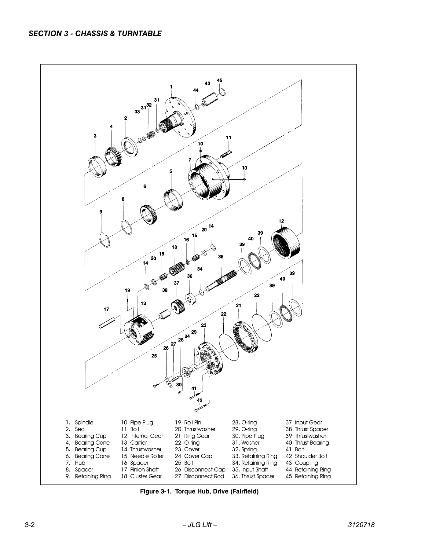
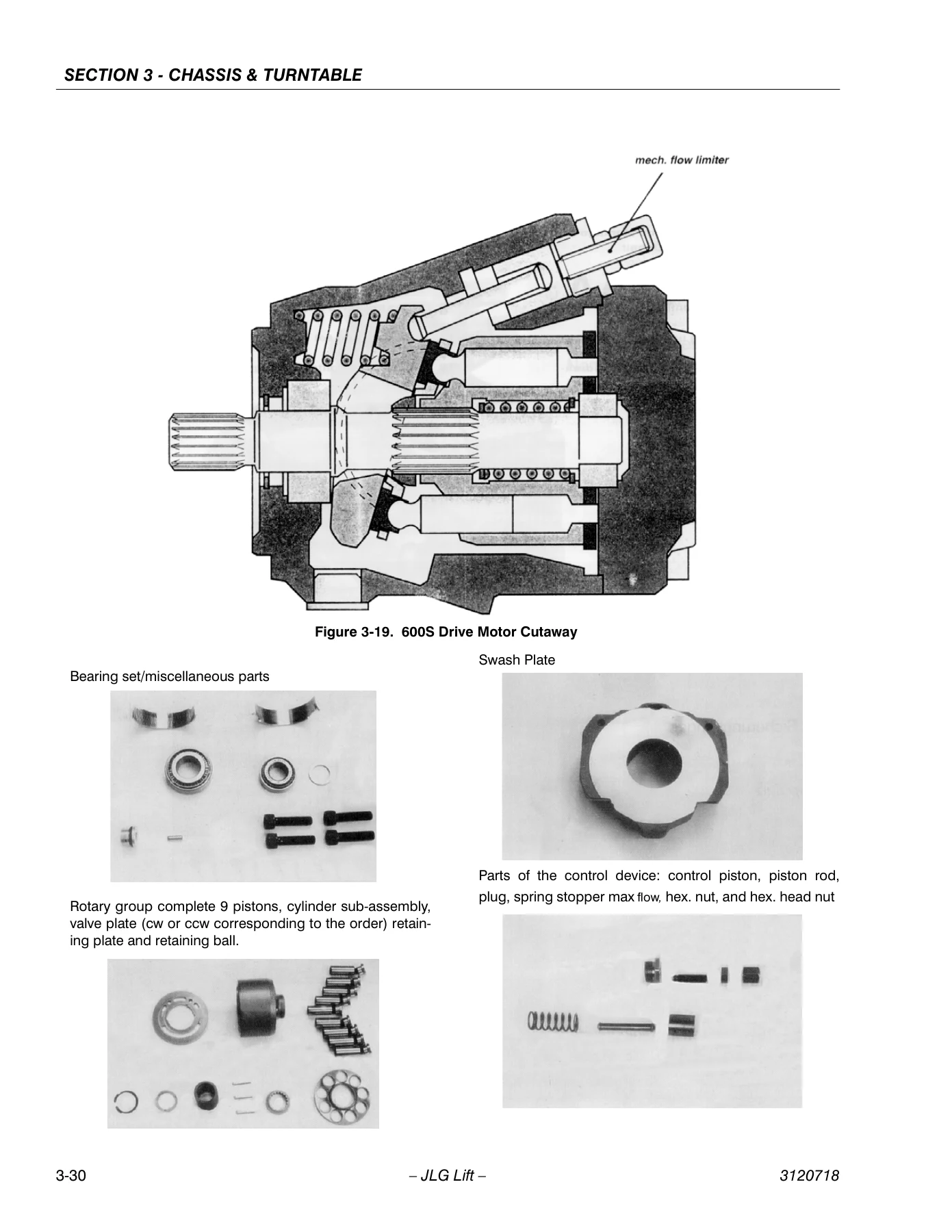
- Section 3 – Chassis & Turntable: Drive torque hub (Fairfield and Auburn Gear), drive torque hub S/N 75606 to present, drive brake Mico, free wheeling option, drive motor (600S, 600A 4WD and 600A 2WD), drive motor adjustment, oscillating axle bleeding and lockout test, steer adjustments, swing hub, swing bearing, swing brake Mico, tilt alarm switch, spark arrester cleaning, rotary coupling, dual fuel system, electric governor, throttle checks, automatic choke adjustment, cold weather starting, glow plugs, Ford EFI engine, Ford LPG system
- Section 4 – Boom & Platform: Boom rope torquing, wear pads, wire rope, boom maintenance (S Models and A Models), tower boom, articulating jib boom, limit switches and cam valve adjustment, platform sections, rotator Helac, drive card setup procedures, foot switch adjustment, boom synchronizing
- Section 5 – Hydraulics: Cylinders theory of operation, cylinder checking procedure, cylinder repair, cylinder removal and installation (S Models and A Models), variable displacement pump M46 series, valves theory of operation, pressure setting procedures, hydraulic component start-up procedures, hydraulic pump w/Hayes pump drive coupling lubrication
- Section 6 – JLG Control System: Introduction, connecting the analyzer, using the analyzer, changing access level, adjusting parameters, machine setup, level vehicle description, machine personality settings, analyzer diagnostics menu structure
- Section 7 – Schematics: General, troubleshooting, hydraulic circuit checks, electrical harnesses, electrical schematics, hydraulic schematics
This JLG 600S 600SJ 660SJ 600A 600AJ repair manual goes far beyond a basic owner’s guide. The engine coverage alone spans Ford LRG-425 and LRG-423 gasoline engines, Deutz F4M1011F and F3M1011F diesel engines, Continental TMD27 diesel, Caterpillar 3024C and 3044C diesel, and Isuzu diesel, giving technicians a single reference for almost every powertrain configuration used on these machines. The JLG Control System section is particularly detailed, covering analyzer connection, fault code retrieval, personality settings and diagnostic menu structure – essential reading when diagnosing ADE (JLG Control System) equipped machines. Because these manuals were distributed only to authorized service personnel and dealers, finding a clean, complete copy for the 600S/600SJ/660SJ/600A/600AJ is difficult. This PDF brings the full document into a format you can search on any device and print individual pages for the workshop floor.
What’s Inside the JLG 600S Service Manual
Every major system on the machine is addressed with procedures, specifications and inspection criteria. The chassis and turntable section walks through disassembly, cleaning, inspection and reassembly of the drive torque hub – covering both Fairfield and Auburn Gear units, plus the S/N 75606 to present design. It also includes the Mico drive brake and swing brake service, the oscillating axle bleed procedure and lockout test, steering stop adjustments for 2WS/2WD and 2WS/4WD configurations, swing bearing bolt condition checks and swing bearing replacement with the correct torque sequence. Drive motor service is documented for both the 600S/600A 4WD motor and the 600A 2WD motor, including shaft seal replacement and, for S models prior to S/N 75606, the drive motor adjustment procedure with the X measurement table.
Engine and fuel system support is extensive. The Ford LPG system section covers the regulator, megajector, mixer and lockoff solenoid, along with diagnostic code descriptions for the megajector. The Ford EFI section covers the ECM, crankshaft position sensor, camshaft position sensor, engine coolant temperature sensor, heated oxygen sensor, intake air temperature sensor, manifold absolute pressure sensor and throttle position sensor, with diagnostic trouble code retrieval and clearing procedures. The cold weather starting chapter addresses carburetor, ignition and fuel checks, glow plug operation, and automatic choke adjustment for Ford engines.
The boom and platform section provides boom rope torquing procedures for S models, wear pad replacement criteria for both tower boom and main boom, wire rope inspection intervals (three-month and seven-year), boom removal and disassembly for S and A models, tower boom service, articulating jib boom removal and installation, limit switch and cam valve adjustments, platform section replacement using huck fasteners, and the Helac rotator disassembly and assembly procedure with actuator timing. Drive card setup procedures are included for lift, swing, drive and flow control cards, with the corresponding function speed and ramp time tables. The boom synchronizing procedure for A models is also documented.
Hydraulic coverage includes the complete cylinder service procedure – disassembly, cleaning, inspection, assembly and torque specifications for all cylinder families on both S and A models. Cylinder removal and installation is documented model by model: main boom telescope cylinder, main boom lift cylinder, upright level cylinder, tower boom lift cylinder, and tower telescope cylinder. The variable displacement M46 series pump section provides troubleshooting flowcharts for neutral difficulty, system overheating, one-direction operation, sluggish response and no operation, plus gauge installation, swashplate neutral adjustment, EDC neutral adjustment, shaft seal replacement, bypass valve service and electrical displacement control service. Pressure setting procedures cover main relief, steer, swing, lift down, platform level, articulating jib boom and 4-wheel steer with the exact PSI and Bar values used on S and A models.
JLG Control System and Diagnostics
Machines built with the ADE (JLG Control System) are identified in the opening pages by serial number, and this manual provides the full analyzer workflow. You get step-by-step instructions for connecting the hand-held analyzer at the platform or ground control box, navigating the top-level menus, entering the access password to reach Level 1, and adjusting personality settings within their allowable ranges. The personality ranges and default tables cover drive accel/decel, forward and reverse minimum and maximum speeds, elevated maximum speed, creep maximum speed, engine RPM, upper lift, tower lift, swing, telescope upper, telescope tower, basket level, basket rotate, jib lift, steer and ground mode speeds for both 600S and 600A. Help fault codes are listed with their flash codes, displayed messages, descriptions and priority for both prior to S/N 66437 and S/N 66937 to present. Machine configuration programming information is also included for model number, engine, glow plugs, engine shutdown, tilt switch, tower lift, tower telescope, jib, 4WS, soft touch system, generator/welder, head and tail lights, broken cable switch, load sensor, function cutout, ground alarm, tower prox switches, drive and flywheel teeth.
Schematics and Electrical Coverage
Section 7 contains the electrical harness diagrams for S models (prior to S/N 61927, S/N 61927 to S/N 63909, S/N 63909 to 75606, and S/N 75606 to present) and A models (prior to S/N 61927, S/N 64249 to S/N 64270, and S/N 64270 to present). Electrical schematics are provided for Deutz or Continental engine, Ford LRG engine, UL Ford LRG, UL Domestic Deutz, UL Domestic LP Gas, ADE with external tilt, Isuzu engine, and ADE. Hydraulic schematics cover S models (four sheets), S models S/N 75606 to present (six sheets), and A models (four sheets). This schematic coverage is essential for tracing circuits and hydraulic flow when diagnosing faults, and it is one of the reasons a complete JLG 600S 600AJ service manual is so valuable to have on hand.
Specifications, Torque Values and Maintenance Data
The first section of this JLG 600SJ service manual delivers the shop data you will reach for again and again: fuel tank capacities, hydraulic oil tank capacities, hydraulic system capacities, torque hub oil volume, engine crankcase capacities for Ford LRG-425, Ford LRG-423, Deutz F4M1011F, Continental TMD27 and Caterpillar 3044C, engine idle and high RPM, alternator output, battery rating, fuel consumption at low and high RPM, horsepower ratings, cooling system capacity, spark plug type and gap, drive motor displacement, drive hub ratios, tire sizes and pressures, toe-in adjustment, swing motor displacement, swing hub ratio, hydraulic gear pump flow and displacement, auxiliary power pump flow, travel speeds, gradeability, turning radii, boom elevation, machine weight, machine height and length, wheelbase, function speeds, torque requirements, hydraulic oil viscosity recommendations, lubrication specifications, cylinder specifications for S and A models, major component weights and critical stability weights. Lubrication charts for S and A models are included with intervals at 3 months/150 hours, 6 months/300 hours, 1 year/600 hours and 2 years/1200 hours, plus the lubricant key (MPG, EPGL, HO, EO) and notes about composite bushings on machines after S/N 38047.
Who This Manual Is For
This JLG service and maintenance manual is written for professional mechanics, fleet maintenance technicians, shop foremen and serious owner-operators who need to service the 600S, 600SJ, 660SJ, 600A or 600AJ boom lift correctly. It is also useful for equipment inspectors who need the correct torque values, pressure settings and inspection intervals to document machine condition. Because the manual covers both S and A model platforms, it is particularly valuable for mixed fleets where a single reference saves shelf space and lookup time. The JLG Control System section makes it suitable for troubleshooting ADE-equipped machines, including reading fault codes, interpreting personality settings and confirming machine configuration programming.
Get the Job Done Right the First Time
With the JLG 600S 600SJ 660SJ 600A 600AJ Service and Maintenance Manual in your hands, you can perform scheduled maintenance, diagnose hydraulic and electrical faults, repair or replace cylinders, service the drive hubs and brakes, adjust the JLG Control System, inspect wire ropes and wear pads, replace swing bearings, and troubleshoot engine and fuel system issues on these machines. Having the correct procedures and specifications matters because boom lifts are safety-critical equipment – incorrect torque on a swing bearing bolt, an improperly bled oscillating axle, or a misadjusted limit switch can lead to unsafe operation. This manual gives you the factory guidance to avoid guesswork and keep every machine in your fleet running safely. The PDF downloads instantly after purchase, requires no shipping, can be stored on any phone, tablet or computer, and individual pages can be printed for use in the shop or at the machine.
Reviews
There are no reviews yet.