
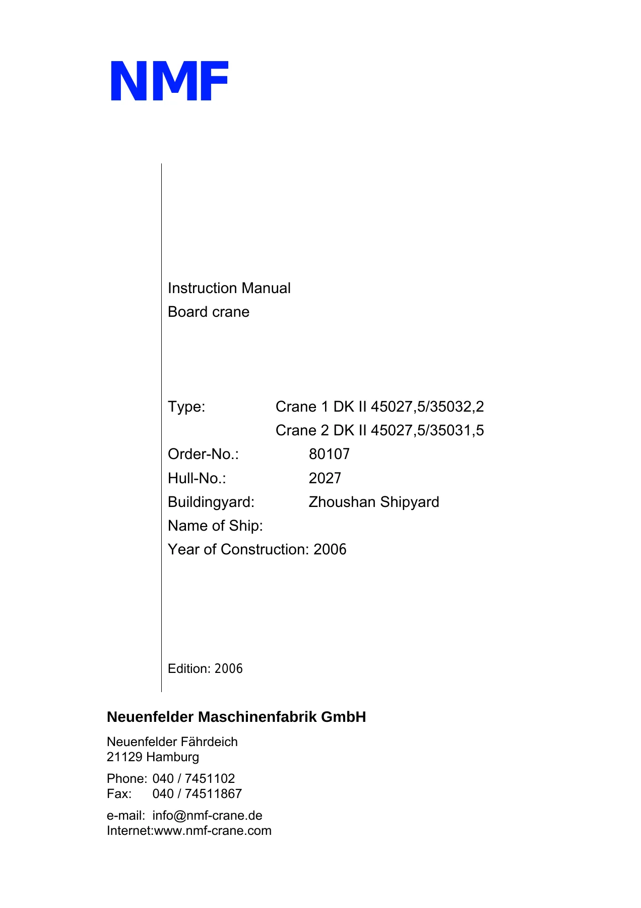
NMF DK II Board Crane Instruction Manual – DK II 45027.5/35032.2 & 45027.5/35031.5 Order 80107
Original price was: $34.95.$19.95Current price is: $19.95.
Complete 2006 NMF instruction manual for the DK II board cranes DK II 45027.5/35032.2 and DK II 45027.5/35031.5 built under Order 80107. 324-page PDF covering operation, hydraulics, electrics, troubleshooting, maintenance, emergency brake hoisting, spare parts and drawings.
Description
NMF DK II Board Crane Instruction Manual – Order 80107
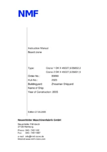
This PDF is the complete NMF DK II board crane instruction manual issued for the two shipboard cranes built under Order 80107 at Zhoushan Shipyard on Hull No. 2027 during 2006. It documents Crane 1, type DK II 45027.5/35032.2, and Crane 2, type DK II 45027.5/35031.5 – twin electro-hydraulically driven loading cranes rated at 45 t, 35 t and 16 t load steps with maximum outreach of 32.2 m and 31.5 m. The document is the 2006 Edition instruction manual published by Neuenfelder Maschinenfabrik GmbH (NMF) of Hamburg, and it runs 324 pages across operation, hydraulic function, electrical controls, troubleshooting, maintenance, emergency procedures, spare parts and drawings.
File Details
- Manual type: Instruction / operation, maintenance and repair manual
- Manufacturer: Neuenfelder Maschinenfabrik GmbH (NMF), Neuenfelder Faehrdeich, 21129 Hamburg
- Crane models: DK II 45027.5/35032.2 (Crane 1), DK II 45027.5/35031.5 (Crane 2)
- Order number: 80107
- Hull number: 2027
- Shipyard: Zhoushan Shipyard
- Year of construction: 2006
- Edition: 2006
- Language: English, with German-language subcontractor documentation appendices
- Page count: 324 pages
- File format: PDF
Chapters Covered
- 1. What is worth knowing about this operating manual – manufacturer, operator’s duty of care, terms and short cuts, symbols, technical amendments, guarantee, copyright
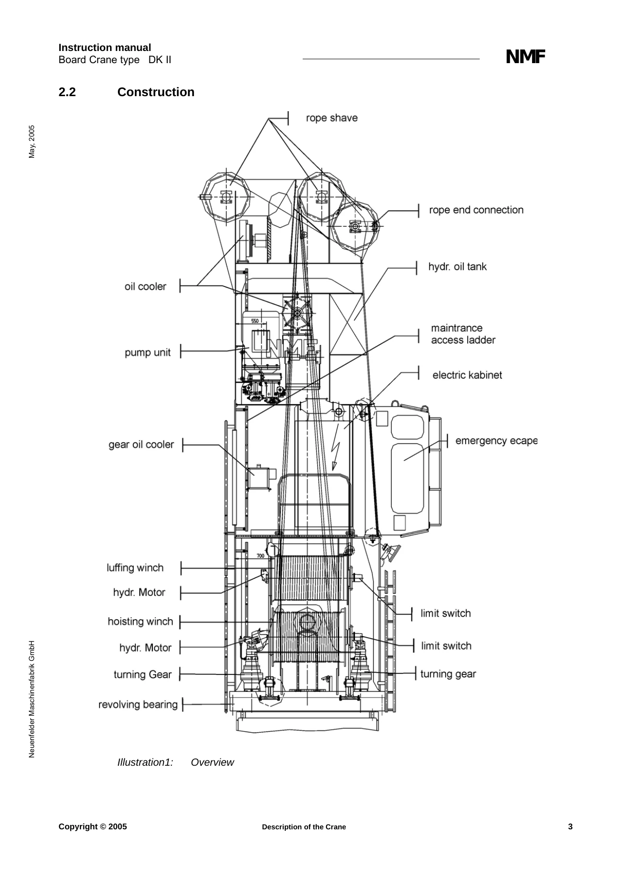
- 2. Description of the Crane – technical data, construction, general aspects, pump unit, lifting gear, luffing gear, turning gear, gear oil cooler, hydraulic oil cooler, heating, slack rope switch, gear limit switch, slip ring assembly, load measuring bolt, electrical components and electronic regulator print card
- 3. Safety – use for the designed purpose, general safety instructions, requirement of personnel, symbols on the crane, warning signals, safety devices and their functional test, anticollision, dangers and behaviour in case of danger, emergency exit
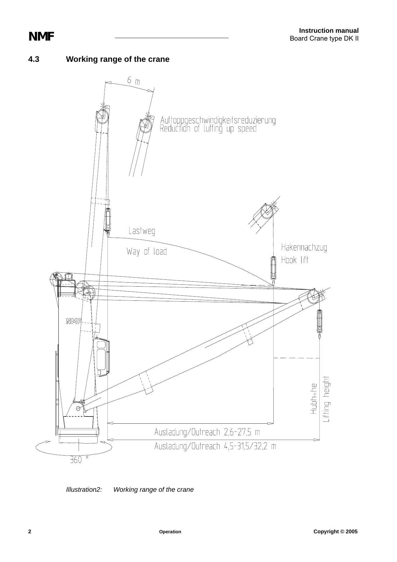
- 4. Operation – safety instructions, requirement of personnel, working range of the crane, operator’s cabin, control panels, inspection prior to starting, switching on, during operation, load stage and half-load stage switching, switch off, emergency shutdown
- 5. Monitoring, Failure, Troubleshooting and Elimination – brake relay monitoring, TEST OPERATION switch, RESET button, fault notification card, fault search diagrams for electrical, lifting gear, luffing gear and slewing gear failures
- 6. Maintenance and Repair – cleaning, greasing, gear and oil changes, gear box inspection, pump distribution gear, gear oil cooler filter, hydraulic oil and filter changes, bottom hook block, roller revolving joint, function and safety inspection, lamellar brakes and lamellar changes, slack rope switch gear, slip ring assembly, load measuring bolts, wire rope maintenance and discard criteria, gear cam limit switch setting, exchanging the Memory-Programmable Control (MPC), battery change, list of lubricants
- 7. Functional Description of Hydraulic – starting the pump unit, venting, heating/cooling system, function of the electro-hydraulic control, hoisting gear including half load and hydraulic overload cut-off, luffing gear, turning gear
- 8. Hoisting of Brakes in Case of Emergency – hoisting gear, jib and slewing gear brake lifting procedures with hand pump
- 9. Illustration – pump unit, load measuring system, current pilot print card, emergency exit, interference pilot print card, gear oil cooler, reset and test switches
- 10. Spare Parts – ordering spare parts, NMF part lists
- 11. Subcontractor Documentation – Brueninghaus Hydromatik axial piston pumps and motors, Zollern winch units, slewing gears, Karl Miller cabin, control lever
- 12. Drawings – maintenance chart, electric wiring diagram, crane housing, general arrangements, jib, rope sheave, anticollision, pump unit, bottom hook block, hydraulic circuit, hydraulic oil tank, fan flap, rope end connection, slack rope connection, energy supply, crane rigs
For the marine engineer or shore technician working on these cranes, the DK II instruction manual is unusually self-contained: it pairs the top-level operation and safety rules with the underlying hydraulic schematics, the electrical troubleshooting trees, and the maintenance intervals and lubricant specifications that keep the crane survey-ready. The inclusion of the Zollern winch unit and Brueninghaus Hydromatik pump spare parts lists alongside the NMF part lists means the reader can trace a failed component down to the correct part number without leaving the document.
What This Manual Lets You Do
Working from this NMF DK II board crane manual, an operator can confidently run the crane through its three load steps – 45 t, 35 t and 16 t – and use the half-load key switch correctly to reach the doubled 0-32 m/min hoisting speed. A maintenance technician can follow the maintenance schedule for the winch gears, turning gears and pump distribution gear, service the gear oil cooler filter and hydraulic oil filter, grease the wire rope and roller revolving joint, and adjust the slack rope switch and gear cam limit switch exactly as NMF specifies.
For electrical fault-finding, the fault search diagrams in the DK II 45027.5/35032.2 and 45027.5/35031.5 instruction manual walk through the most common failures – motor will not start, lifting winch not turning, luffing gear not turning, crane not slewing – linking each symptom to its probable cause and the correct remedy. The brake relay monitoring section shows where to read the fault lamps on the interference pilot print card, and the RESET button procedure explains how to bring the crane back after a hose rupture or a gear oil cooler trip.
The emergency section is equally practical: it gives the hand pump connection steps for hoisting the hoisting gear, luffing gear and slewing gear brakes when the main power has failed, including the maximum brake opening pressure and the throttle and bypass valve settings that must be restored afterwards.
Why It Matters
Shipboard cranes are surveyed and load-tested, and the correct NMF procedures and specifications for limit switch adjustment, load pressure switch setting, brake inspection and rope discard criteria are what keep the crane inside its class requirements. The technical data in this manual – 45 t capacity at 27.5 m outreach with +/- 5 degrees heeling and +/- 2 degrees trim, 160 kW main pump motor, 440 V / 60 Hz supply, 0-0.8 rpm turning speed, 70 s luffing time – is the reference against which any deviation should be judged.
Delivery
IMAGES PREVIEW
The NMF DK II board crane instruction manual is delivered as an instant-download PDF. There is no shipping and no waiting: as soon as payment is confirmed you can open the file, search it, print the sections you need for the workshop, and keep the complete document on a laptop, tablet or phone at the crane. Because both cranes in the order are covered in the same file, a single purchase serves Crane 1 and Crane 2.

Reviews
There are no reviews yet.