
Noblelift FE4P30-35N Forklift Spare Parts List BPT-001 PDF – Parts Catalog
Original price was: $52.95.$34.95Current price is: $34.95.
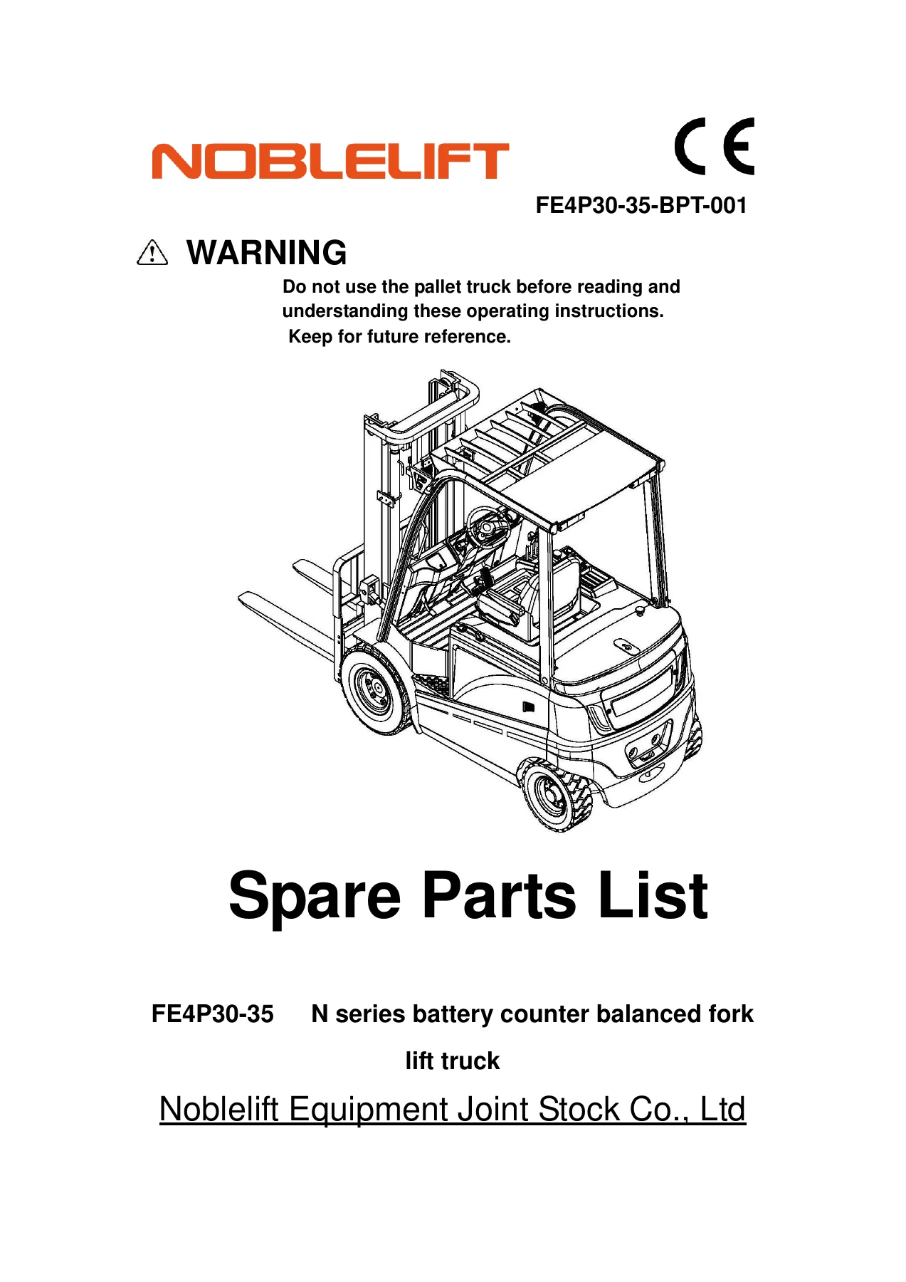
Complete illustrated spare parts list for Noblelift FE4P30-35N series 3.0t and 3.5t battery counterbalanced forklift trucks. Document BPT-001 with exploded views and part numbers for every major assembly.
Description
Noblelift FE4P30-35N Spare Parts List BPT-001
This Noblelift FE4P30-35N series spare parts list is the complete illustrated parts catalog for the 3.0t and 3.5t battery counterbalanced forklift trucks. Published under document number BPT-001, it covers every assembly from the drive axle and gearbox to the mast, lifting cylinders, hydraulic system, electrical components, and cab fittings. Each figure presents an exploded view with a numbered parts table giving the original coding, description, quantity, and notes for every component. Whether you are rebuilding a gearbox, replacing a hydraulic hose, or ordering a single bolt, this Noblelift FE4P30-35N parts catalog gives you the exact reference to order the right part the first time.
File Details
- Manual Type: Spare Parts List
- Brand: Noblelift
- Model: FE4P30-35N series battery counterbalanced forklift truck (3.0t and 3.5t)
- Document Number: BPT-001
- Language: English
- Page Count: 181
- File Format: PDF
Chapters Covered
- Drive Axle & Gearbox
- Drive Wheel Assembly & Lifting Motor
- Battery & Battery Box Cover
- Frame, Counterweight & Body Panels
- Steering Axle, Cylinder & Mechanism
- Foot Brake & Parking Brake
- Hydraulic System & Multi-Directional Control Valves
- Mast, Lifting Cylinders & Pipelines
- Forks & Fork Carriers
- Side Shifter & Pipeline Installation
- Electrical System & Electronic Control (CURTIS)
- Labels & Data Nameplates
Drive Axle & Gearbox
Figure 2 breaks down the drive axle with left and right brake assemblies, the drive axle housing, oil seals, bearings, hub, and half shaft. Figure 3 covers the gearbox including the input shaft assembly, box cover, bearings, gears, and adjusting washers. Figure 4 continues with differential components — right differential carrier, gear ring, washers, spacers, and bolts.
Drive Wheel & Lifting Motor
Figure 5 lists drive wheel options for both 3.0t and 3.5t models, covering pneumatic, solid, and environmental protection tyres in 23×9-10 and 23×10-12 sizes, along with rim assemblies. Figure 6 details the AC lifting motor installation with anti-vibration pads, bushings, washers, bolts, and gear pump.
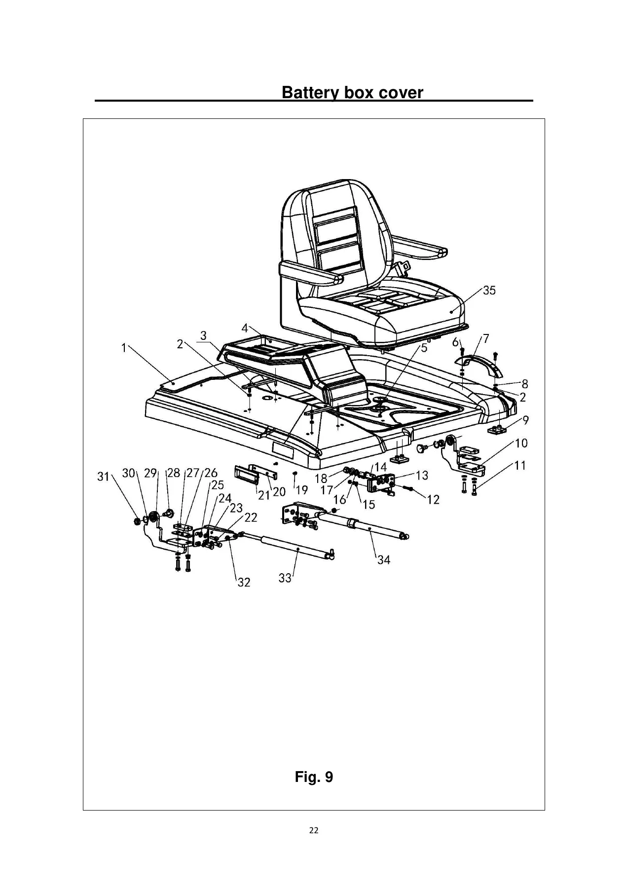
Battery & Battery Box
Figure 7 covers battery options across 80V500Ah and 80V560Ah capacities in weld and bolt configurations, plus the battery bracket welding. Figure 8 shows the foot pedal assembly. Figure 9 provides a detailed exploded view of the battery box cover with hinges, locks, handles, air springs, and seat mounting components.
Frame, Counterweight & Body Panels
Figures 10 through 16 cover the right side door, right and left side plates, valve cover, counterweight assembly, frame sidesway, and ceiling-mounted frame variants. Components include side door locks, hinges, gas springs, bolts, washers, and damping pads.
Steering System
Figure 17 covers the control panel. Figure 18 details the steering mechanism and installation including the steering column, wheel, adjustable handle, and steering gear BZZ5-E100BCF-H6. Figure 23 breaks down the steering axle with left and right knuckle assemblies, bearings, pins, and seals. Figure 24 covers the steering cylinder with its sealing kit.
Brake System
Figure 19 covers the foot brake with pedal welding, brake pump assembly, hydraulic steel pipes, and connecting components. Figure 20 details the parking brake with pedal welding, hand brake wire rope, micro switch, springs, and mounting hardware.
Hydraulic System & Control Valves
Figures 27 through 29 cover the multi-directional control valve in bigeminy, trigeminy, and four-joint configurations, including handles, control levers, axles, springs, and connecting rods. Figure 30 details the hydraulic system with joints, hoses, hose clamps, and hydraulic hose assemblies. Figure 26 covers the working cylinder mechanism with drain plug, cylinder welding, screen filter, and oil dipstick assembly.
Mast & Lifting Cylinders
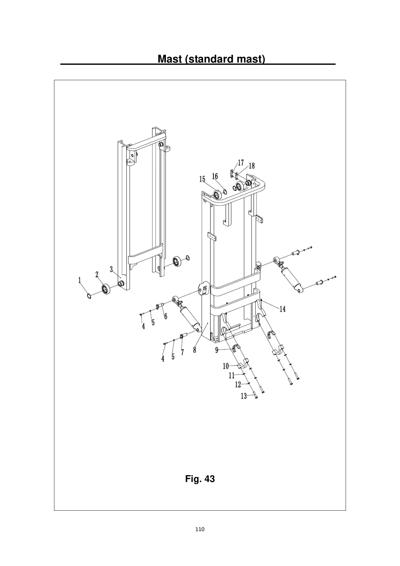
Figures 31 through 33 cover mast lifting pipelines for standard, two-stage full free, and three-stage full free configurations. Figures 43 through 45 detail the mast assemblies. Figures 46 through 53 cover lifting cylinders across standard, two-stage, and three-stage configurations for both 30T and 35T models, including lifting chains, chain wheel bearings, and seal kits.
Forks & Fork Carriers
Figures 37 and 38 list fork options for 30T and 35T in various dimensions. Figures 39 through 42 cover fork carriers for standard mast, two-stage full free, and three-stage full free configurations, including rollers, side rollers, load backrest welding, and adjustment components.
Side Shifter & Pipeline Installation
Figures 34 through 36 cover side shifter and pipeline installation for standard mast, two-stage full free, and three-stage full free configurations, with hydraulic hose assemblies, pulleys, press plates, and side shift assemblies.
Electrical System & Electronic Control
Figure 56 covers the electric system with micro switches, combination switch, lights, key switch, horn, indicators, transducers, emergency switch, and truck body harness. Figure 57 details the CURTIS electronic control elements including fuse box, controllers, buzzer, relay, fuse, and contactor. Figure 58 covers the power connector assembly with battery cables.
Labels & Data Nameplates
Figures 59 and 60 cover labels in Chinese and English, including warning labels, tyre pressure labels, safety labels, and product model stickers. Figures 61 and 62 cover data nameplates in Chinese and English with load capacity diagrams.
Why This Parts List Matters
Ordering the wrong part for a forklift wastes time and money. This Noblelift FE4P30-35N spare parts catalog eliminates guesswork by giving you exploded diagrams tied directly to part numbers, descriptions, and quantities. Every assembly is covered — from the gearbox internals to the smallest washer on the overhead guard. The document includes both metric and standard hardware callouts, seal dimensions, bearing numbers, and optional configurations so you can match your exact machine.
IMAGES PREVIEW
Instant PDF Delivery
This Noblelift FE4P30-35N parts list PDF is available for immediate download after purchase. No shipping, no waiting. View it on any device — laptop, tablet, or smartphone — and print the pages you need for the workshop. Keep the complete parts catalog on hand for every maintenance and repair job on your FE4P30N or FE4P35N forklift.
Reviews
There are no reviews yet.