
Normet Alpha 30 DC7 Spare Parts Manual – EQ177 Illustrated Parts Catalog PDF
Original price was: $39.95.$23.95Current price is: $23.95.
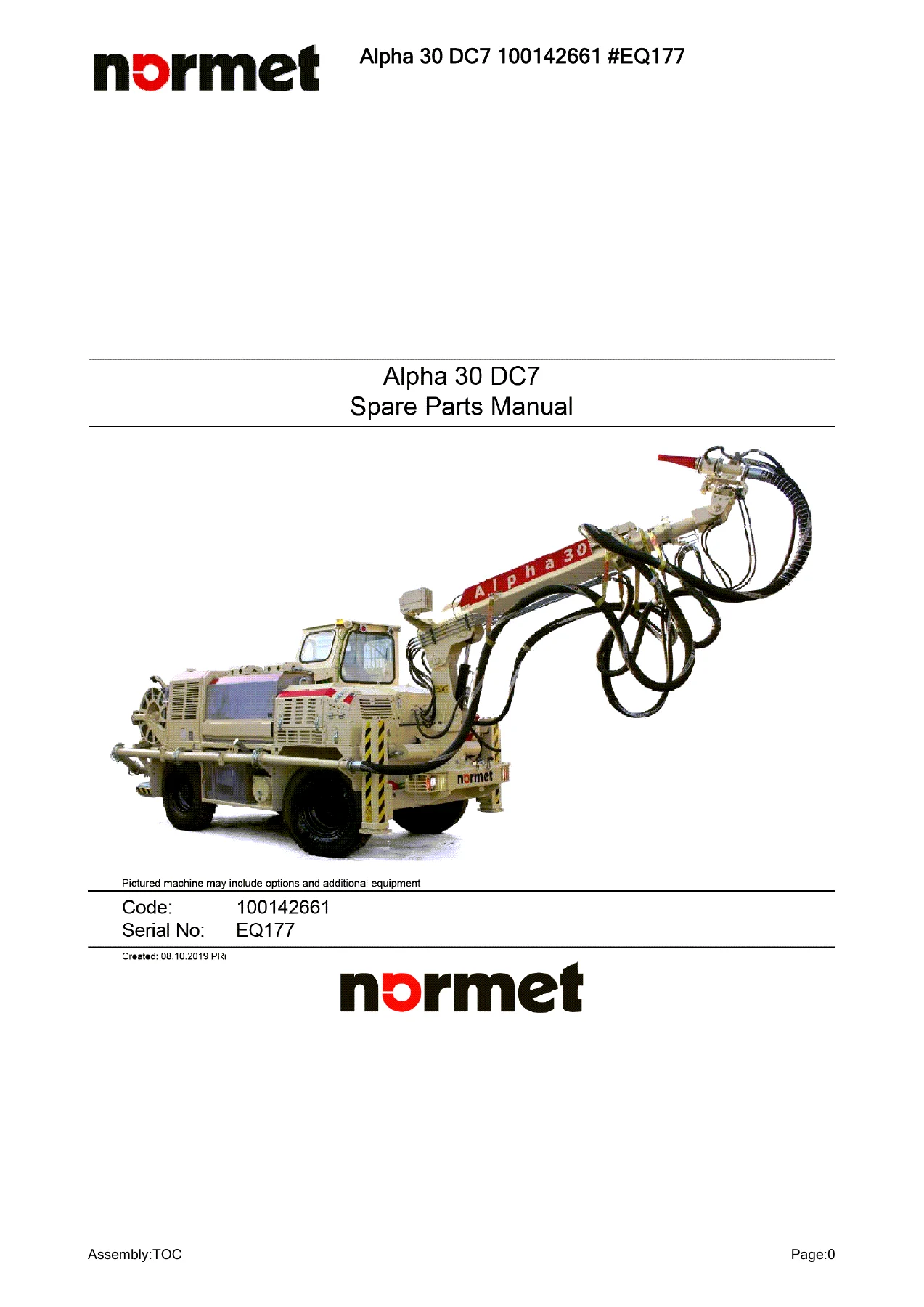
Complete illustrated spare parts manual for the Normet Alpha 30 DC7 (machine code 100142661, serial EQ177) – covering the spraying boom, concrete pump, accelerator system, transmission, electrics, cabin, engine installation and more, with part numbers, quantities and exploded assembly drawings.
Description
Normet Alpha 30 DC7 Spare Parts Manual – EQ177
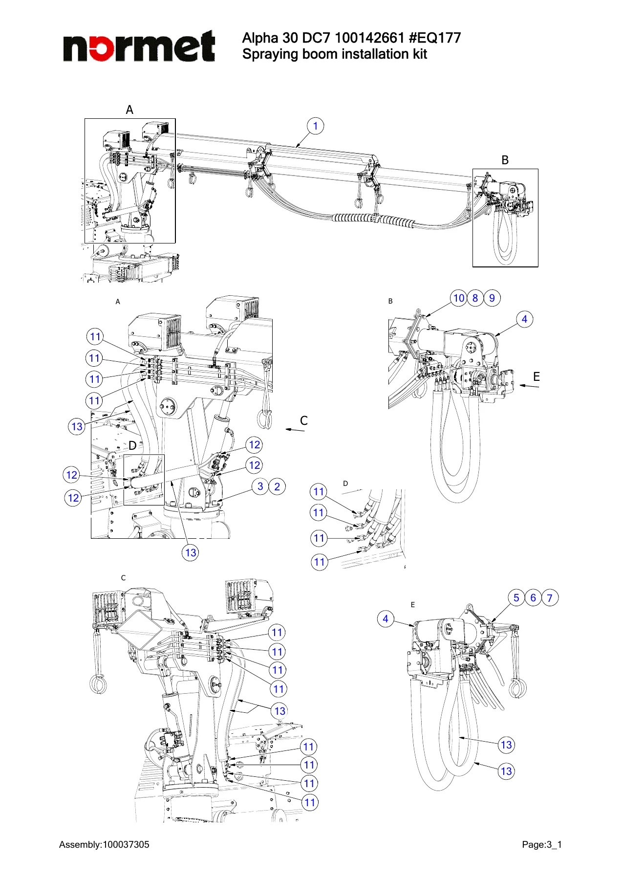
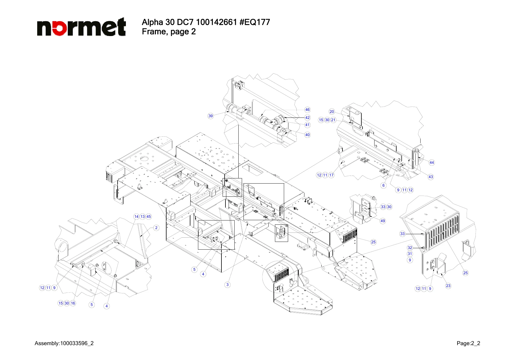
This is the full illustrated spare parts manual for the Normet Alpha 30 DC7, published under machine code 100142661 and serial number EQ177. It is a parts identification document built around exploded assembly drawings: every drawing carries numbered callouts that map to a parts list giving the part number, the description, the standard designation where applicable, and the quantity required. If you need to look up, confirm or order a component on an Alpha 30 DC7, this is the document that turns a drawing reference into an orderable part number.
File Details
- Manual type: Spare parts manual / illustrated parts catalog
- Brand: Normet
- Machine: Alpha 30 DC7
- Machine code: 100142661
- Serial number: EQ177
- Document date shown: Created 08.10.2019
- Language: English
- Format: PDF
- Page count: 640 pages
- Contents: Parts lists, exploded assembly drawings, hydraulic and pneumatic fittings, safety label placement diagrams, Deutz engine spare parts catalogue
Chapters Covered
- 1 Service parts / Safety symbols – carrier service parts, engine service parts, symbol plates, warning tape, tilt meters, safety label layouts
- 2 Standard parts – frame, wheel assemblies, support legs, tank covers, hydraulic oil tank, fuel tank, spot lights, side footstep, fire extinguisher
- 3 Spraying boom SB307 – boom installation kit, main beam, middle and front telescopic beams, spraying head, boom control valve and fittings, turn table, turning unit, cylinders and seal kits
- 4 Concrete pump – mechanical assembly, control blocks, S-tube control block, forward/reverse control block, speed control block, manifolds, pump fittings, pistons, hopper assembly, limit switch, S-tube valve, outlet part, vibrator assembly, water manifold, water hose
- 5 Spraying equipment – concrete line, concrete line installation kit, fastening clamps, concrete tube installation supports, nozzle tip assembly
- 6 Accelerator system – accelerator installation kit, accelerator pump assembly and main drawing, accelerator tanks, ball valve fittings, bleeding hose, accelerator hose, interconnection hose, throttle check valve fittings, spare part kits
- 7 Transmission – front axle mechanical assembly, rear axle mechanical assembly, central drive shaft, cardan shaft, throttle check valve assembly, directional valve fittings, transmission control box installation, front axle central housing, differential, hub reduction, brakes, steering, trunnion
- 9 Electrics – dashboard, terminal box installations TB1 to TB7, emergency push button kits, general electric schema, terminal box circuit diagrams
- 10 Grease system – grease pump installation and grease pump breakdown
- 11 Remote / Radio control system – radio remote control in four parts, receiver installation, receiver support, receiver assembly, battery charger
- 12 Engine Installation kit – engine installation pages, engine assembly, pressure filter assembly, directional valve assembly, hydraulic return manifold, hydraulic pump assemblies, single gear pump installation, air cleaner intake line, Deutz engine spare parts catalogue
- 13 Exhaust line kit – exhaust pipe installation and exhaust pipe assembly
- 14 Engine hood – engine hood installation, engine hood insulations, hood panels, service hatches
- 16 Cabin Kit – cabin installation kit, cabin assembly, spot light assemblies, brake valve fittings, cabin lower door, throttle leverage, pressure accumulator, directional control valve, steering valve fittings, cabin gate, window assemblies, cabin door with air conditioning, side panel
- 18 Reverse camera installation – camera, monitor, reversing sensors, display sensor, power cable, sensor cable
- 19 Air conditioning installation – air conditioning installation, air conditioning device, control panel, compressor assembly
- 20 Safety Kit – first-aid kit, measure connector, safety whips installation
- 21 Air compressor – air compressor installation, air manifold block, compressor assembly, pressure relief valve fittings, controller device box, compressor unit and air unit
How the Manual Is Built
Each chapter opens with an assembly overview page, followed by one or more exploded or isometric drawings of the sub-assembly. Callout balloons on the drawing correspond to numbered rows in the accompanying parts list, so a single reference number leads you straight to the part number, standard designation and required quantity. Where a component is itself a serviceable assembly, the manual breaks it down further – cylinders, valves, control blocks, pumps and axles all have their own exploded pages with seal kits, bearings, circlips, O-rings and fasteners listed individually.
Fittings are handled with unusual thoroughness. Straight thread connectors, angle couplings, T-fittings, L-fittings, reduction fittings, elbow fittings, SAE flanges, USIT seal rings, hose clamps and pressure measuring points are all listed with their specific designations and thread sizes, which makes it practical to rebuild a hydraulic or pneumatic circuit correctly rather than approximately.
Machine Systems You Can Identify and Order Parts For
Spraying Boom SB307
The boom chapter covers the full SB307 assembly: the boom base, main beam, middle and front telescopic beams, the inner and outer extension cylinders, lifting cylinder, sling and lifting eye, joint pins, scrapers, rollers and roller assemblies, protection covers, hydraulic piping and hoses, work light cover and the spraying head. The boom control valve is broken out into its own fittings section, including the handle lever kit, basic modules, main spools in different flow ratings, shock valves, electric activations and covers.
Concrete Pump
The concrete pump section covers the mechanical assembly, hopper and hopper grill, S-tube valve, wear lining, outlet part, differential cylinders, change over cylinders, mixer, hydraulic motor, joint forks, bearing housing and the full valve block set. Control blocks are documented separately – concrete pump control block, S-tube control block, forward/reverse control block and speed control block – each with their own fittings page and, where applicable, an internal component breakdown covering logic elements, subplates, solenoids, cartridge relief valves, orifices and shutters.
Transmission and Axles
Transmission coverage includes the front and rear axle mechanical assemblies, central drive shaft with flange, support bearing and axle key, cardan shafts with tube and joint fork, the throttle check valve assembly, the directional valve fittings and the transmission control box. The front axle is expanded into its central housing, differential, hub reduction, brakes, steering and trunnion sub-chapters, listing bevel gear sets, differential side gears and pinions, friction washers, bearings, ring nuts, planet gears, wheel hubs, ring gears, brake discs, pistons and seal kits.
Electrics
Electrics are documented through the dashboard and seven terminal boxes (TB1, TB2, TB4, TB5, TB6 and TB7 plus the installation grouping), each with its own parts list of electric boxes, rails, terminal blocks, end plates, stoppers, relays, relay bases, miniature circuit breakers, blade fuses, signal lights, toggle switches, connectors, gaskets and ID tags. Emergency push button kits, the EMR-control box installation kit and the battery installation kit are listed as separate assemblies, and the general electric schema is included.
Cabin, Hood and Operator Station
The cabin chapter lists the cabin installation kit with its hydraulic hoses, the cabin frame, dashboard, steering wheel and column, seat, safety belt, brake pedal, electric throttle pedal, spot light assemblies, windows and seals, cabin door with air conditioning device, air conditioning control panel, compressor assembly and the terminal box fitted inside the cab. The engine hood chapter covers the hood panels, insulation and noise control materials, gas springs, butt hinges, lever locks, hand rails, roof plates and the removable service hatches.
Engine Installation and Exhaust
The engine installation chapter lists the engine assembly, cooler complete with oil, air and water cooler cells, three hydraulic pump assemblies, torsional vibration damper, installation flanges, charged air pipes, water hoses, expansion tanks, level sensors, air cleaner and intake line, and the associated hydraulic hose set with lengths and fitting designations. The exhaust chapter covers the exhaust pipe installation, exhaust pipe assembly, gaskets, exhaust purifier and fastening clamps. A separate Deutz spare parts catalogue covering the engine family is included at the back of the document.
Accelerator, Grease, Remote Control and Air Compressor
The accelerator system chapter documents the installation kit, pump assembly, two tank assemblies, ball valve fittings, bleeding and interconnection hoses, throttle check valve fittings and the complete set of spare part kits for the pump (hose set, rotor set, bearing set, hydraulic motor seal kit, screws/nuts/washers and motor adapter/clutch). The grease system covers the grease pump installation and the internal breakdown of the pump itself. The remote control chapter documents the radio remote control, receiver installation and support, receiver complete and battery charger. The air compressor chapter covers the compressor installation, air manifold block, compressor assembly, pressure relief valve fittings, controller device box and the compressor unit breakdown including air inlet valve, discharge valve, oil cooler cell, oil separators and air cleaner elements.
Who This Manual Is For
This is a working document for anyone who has to keep an Alpha 30 DC7 running and needs to order the right component the first time – workshop technicians, parts managers, maintenance planners and owners running the machine in sprayed concrete or ground support work. Because the Alpha 30 DC7 is a machine-specific configuration (code 100142661, serial EQ177), the parts lists reflect the assemblies actually fitted to that build rather than a generic model overview. That is exactly why the drawings and part numbers matter: a fitting or a seal kit identified from an illustration avoids the guesswork of matching components by eye or by description alone.
Why Correct Part Identification Saves Time and Money
On a machine like the Alpha 30 DC7, downtime is expensive and a wrong part is a second downtime. The Normet Alpha 30 DC7 Spare Parts Manual – EQ177 Illustrated Parts Catalog PDF gives you the callout-to-part-number relationship directly from the manufacturer’s own assembly drawings, covering seal kits, bearings, circlips, fasteners, hydraulic fittings, hose assemblies and complete sub-assemblies. You can quote part numbers straight to your supplier, confirm quantities per assembly before ordering, and check which items belong to a specific sub-assembly when a repair turns out to be deeper than first thought.
Because the manual documents assemblies as they are actually built, it also helps during strip-down. Exploded views show the order in which components stack – bearings, spacers, circlips, covers, flanges and fasteners – so reassembly follows the drawing rather than memory. The hydraulic and pneumatic fittings sections are especially useful when a hose or coupling has to be replaced, since thread designations and coupling types are listed explicitly.
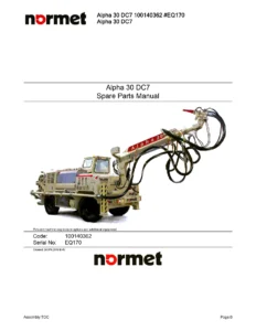
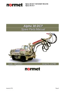
IMAGES PREVIEW
Instant PDF Delivery
The manual is supplied as a PDF and is available immediately after payment. There is no shipping, no waiting for a parcel and no risk of a damaged paper copy. Open it on a laptop on the bench, on a tablet next to the machine, or print the drawing and parts list pages you need for the job and take them with you. The searchable page structure makes it practical to jump between a drawing and its parts list, and the whole 640-page document stays in one file for quick reference. Order the Normet Alpha 30 DC7 Spare Parts Manual – EQ177 and put the correct part number in the requisition the first time.

Reviews
There are no reviews yet.