Panasonic Th 103vx200 Service Repair Manual Guide – PDF DOWNLOAD
Original price was: $21.95.$14.95Current price is: $14.95.
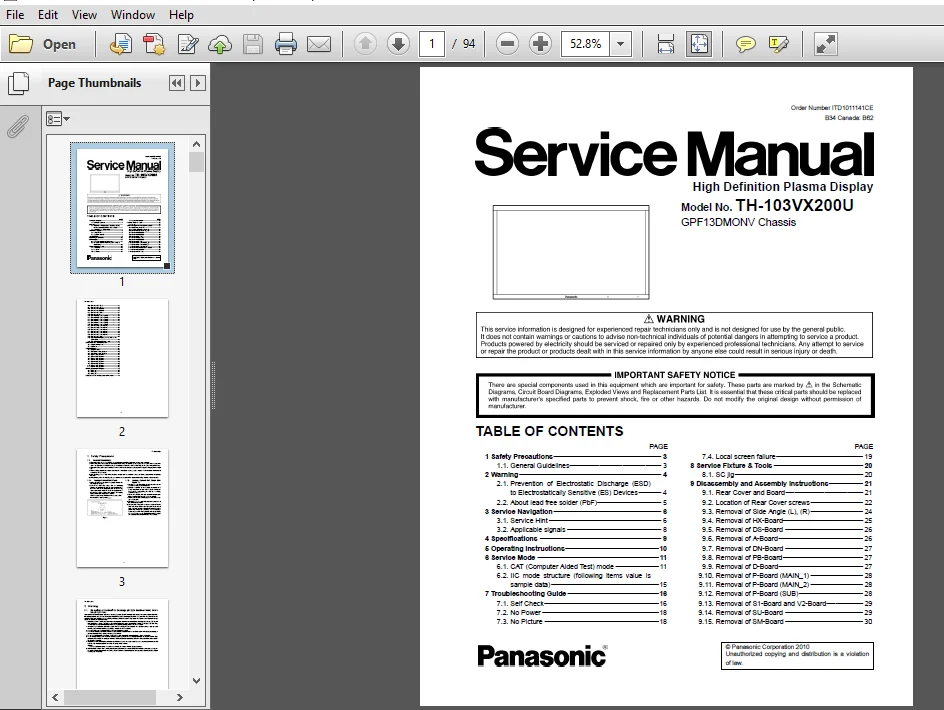
Panasonic Th 103vx200 Service Repair Manual Guide
Description
Panasonic Th 103vx200 Service Repair Manual Guide
PANASONIC TH 103VX200 SERVICE REPAIR MANUAL GUIDE – PDF DOWNLOAD:
IMAGES PREVIEW OF THE MANUAL:


TABLE OF CONTENTS:
Panasonic Th 103vx200 Service Repair Manual Guide
1 Safety Precautions 3
1.1. General Guidelines 3
2 Warning 4
2.1. Prevention of Electrostatic Discharge (ESD)
to Electrostatically Sensitive (ES) Devices 4
2.2. About lead free solder (PbF) 5
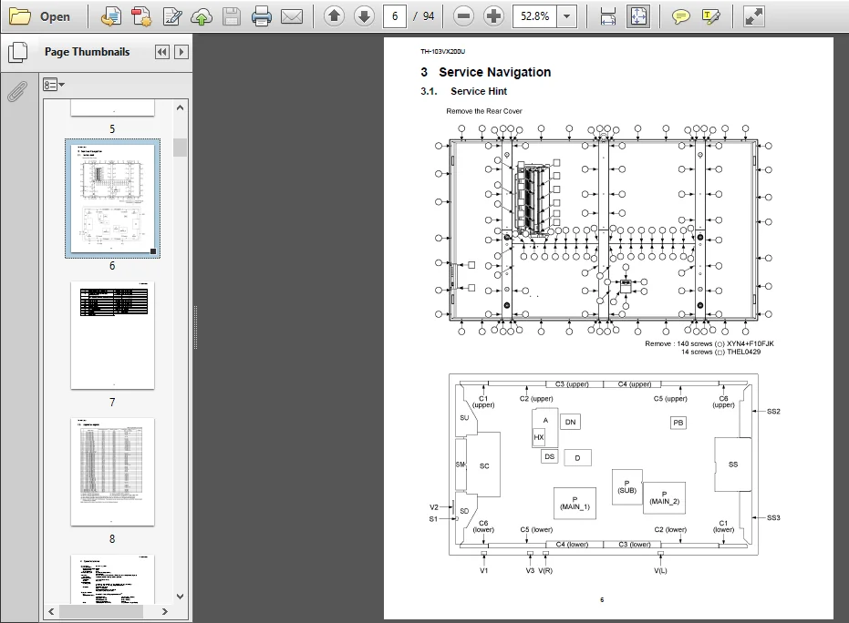
3 Service Navigation 6
3.1. Service Hint 6
3.2. Applicable signals 8
4 Specifications 9
5 Operating Instructions10
6 Service Mode 11
6.1. CAT (Computer Aided Test) mode 11
6.2. IIC mode structure (following items value is
sample data) 15
7 Troubleshooting Guide 16
7.1. Self Check16
7.2. No Power 18
7.3. No Picture 18
7.4. Local screen failure 19
8 Service Fixture & Tools 20
8.1. SC jig 20
9 Disassembly and Assembly Instructions 21
9.1. Rear Cover and Board 21
9.2. Location of Rear Cover screws 22
9.3. Removal of Side Angle (L), (R) 24
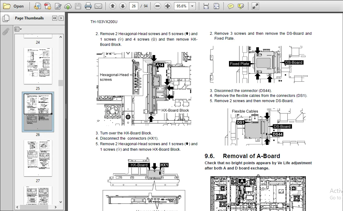
9.4. Removal of HXBoard 25
9.5. Removal of DSBoard 26
9.6. Removal of ABoard 26
9.7. Removal of DNBoard 27
9.8. Removal of PBBoard 27
9.9. Removal of DBoard 27
9.10. Removal of PBoard (MAIN_1) 28
9.11. Removal of PBoard (MAIN_2) 28
9.12. Removal of PBoard (SUB) 28
9.13. Removal of S1Board and V2Board 29
9.14. Removal of SUBoard 29
9.15. Removal of SMBoard 30
219.16. Removal of SDBoard 31
9.17. Removal of SCBoard 32
9.18. Removal of SS2Board 33
9.19. Removal of SS3Board 33
9.20. Removal of SSBoard 34
9.21. Removal of Fan 34
9.22. Removal of C1Board (upper) 35
9.23. Removal of C2Board (upper) 36
9.24. Removal of C3Board (upper) 36
9.25. Removal of C4Board (upper) 37
9.26. Removal of C5Board (upper) 37
9.27. Removal of C6Board (upper) 37
9.28. Removal of C1Board (lower) 37
9.29. Removal of C2Board (lower) 38
9.30. Removal of C3Board (lower) 38
9.31. Removal of C4Board (lower) 39
9.32. Removal of C5Board (lower) 39
9.33. Removal of C6Board (lower) 39
9.34. Removal of AC Inlet 40
9.35. Removal of Front Glass, V1, V3, VBoard and
Cabinet Assy 40
9.36. Removal of Plasma Display Panel 44
10 Measurements and Adjustments 49
10.1. Adjustment Procedure 49
10.2. Adjustment 54
11 Block Diagram 58
11.1. Diagram Notes 58
11.2. Main Block (1 of 2) Diagram 59
11.3. Main Block (2 of 2) Diagram 60
11.4. Block (1 of 8) Diagram 61
11.5. Block (2 of 8) Diagram 62
11.6. Block (3 of 8) Diagram 63
11.7. Block (4 of 8) Diagram 64
11.8. Block (5 of 8) Diagram 65
11.9. Block (6 of 8) Diagram 66
11.10. Block (7 of 8) Diagram 67
11.11. Block (8 of 8) Diagram 68
12 Wiring Connection Diagram 70
12.1. Wiring (1) 70
12.2. Wiring (2) 72
12.3. Wiring (3) 74
13 Exploded View and Replacement Parts List 75
FILE FORMAT:
LANGUAGE:ENGLISH
PAGES:94
DOWNLOADABLE:YES
FILE TYPE:PDF
PLEASE NOTE:
- This is the SAME manual used by the dealers to troubleshoot any faults in your vehicle. This can be yours in 2 minutes after the payment is made.
- Contact us at [email protected] should you have any queries before your purchase or that you need any other service / repair / parts operators manual.