Panasonic TH-L32D25C TH-L37D25C TH-L42D25C LCD TV Service Manual PDF
Original price was: $100.00.$15.95Current price is: $15.95.
Official Panasonic service manual (Chinese language) for TH-L32D25C, TH-L37D25C, and TH-L42D25C LCD television models with LA02 chassis. This comprehensive 139-page technical manual (Document SMT1007002CC, 2010) covers complete specifications, circuit diagrams, disassembly procedures, troubleshooting, adjustment procedures, and repair information for 32-inch, 37-inch, and 42-inch Full HD LCD TVs. Essential for electronics service technicians repairing Panasonic LCD televisions.
Description
Panasonic TH-L32D25C TH-L37D25C TH-L42D25C LCD TV Service Manual SMT1007002CC PDF DOWNLOAD
DESCRIPTION:
Panasonic TH-L32D25C / TH-L37D25C / TH-L42D25C LCD TV – Complete Factory Service Manual
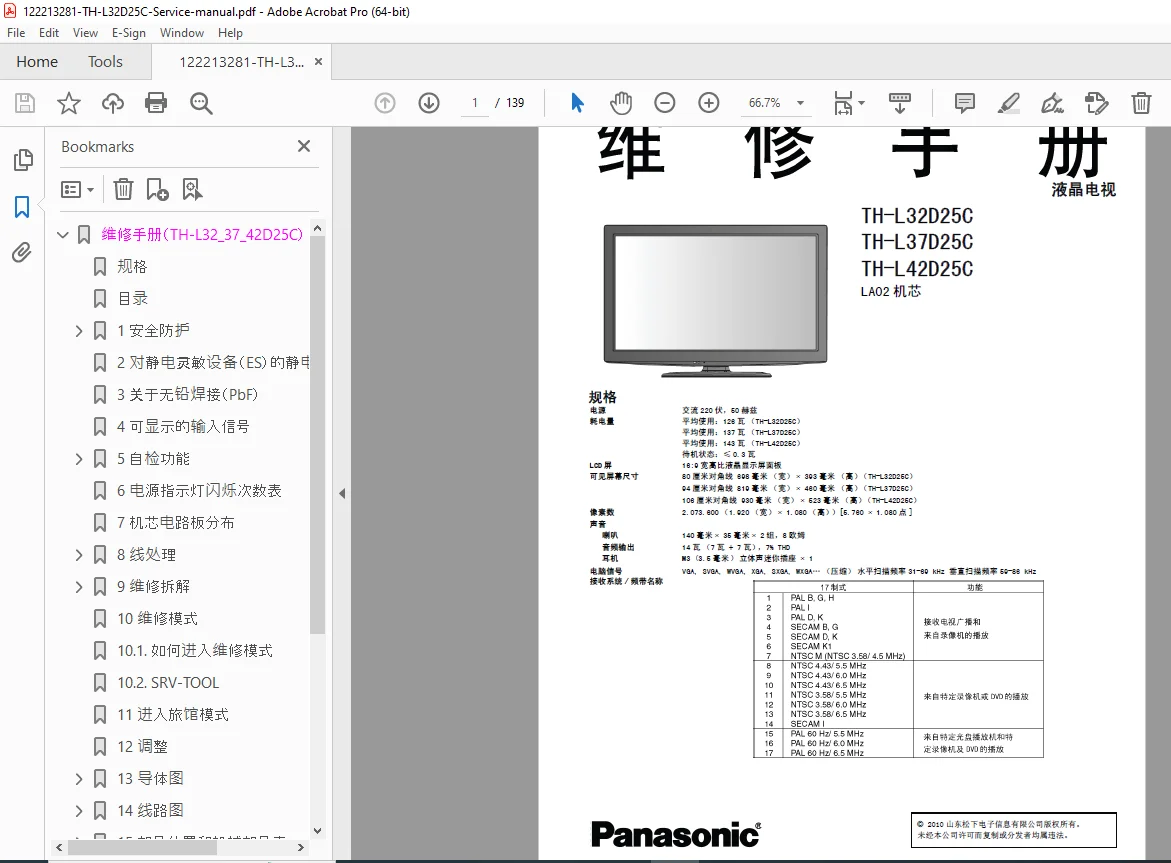
This is the official factory service manual (Document No. SMT1007002CC, 2010) published by Shandong Panasonic Electronic Information Co., Ltd. for the TH-L32D25C (32″), TH-L37D25C (37″), and TH-L42D25C (42″) LCD television models with LA02 chassis. This comprehensive technical guide provides electronics service technicians with complete specifications, circuit diagrams, disassembly procedures, troubleshooting methods, and repair information for these Full HD LCD televisions.
File Details:
- Manual Name: Panasonic LCD TV Service Manual
- Models Covered: TH-L32D25C (32″), TH-L37D25C (37″), TH-L42D25C (42″)
- Chassis: LA02
- Document Number: SMT1007002CC
- Language: Chinese (中文)
- Publication Date: 2010
- Publisher: Shandong Panasonic Electronic Information Co., Ltd. (山东松下电子信息有限公司)
- Manual PDF Quality: Excellent – Factory original with detailed diagrams
- Total Pages: 139
MODELS COVERED:
TH-L32D25C (32-inch LCD TV):
- Screen Size: 80 cm diagonal (698mm W × 393mm H)
- Power Consumption: Average 126W, Standby ≤0.3W
- Dimensions with Stand: 795mm × 564mm × 217mm
- Dimensions TV Only: 795mm × 521mm × 77mm
- Weight with Stand: 14.0 kg net
- Weight TV Only: 12.0 kg net
TH-L37D25C (37-inch LCD TV):
- Screen Size: 94 cm diagonal (819mm W × 460mm H)
- Power Consumption: Average 137W, Standby ≤0.3W
- Dimensions with Stand: 917mm × 632mm × 287mm
- Dimensions TV Only: 917mm × 590mm × 77mm
- Weight with Stand: 17.5 kg net
- Weight TV Only: 14.5 kg net
TH-L42D25C (42-inch LCD TV):
- Screen Size: 106 cm diagonal (930mm W × 523mm H)
- Power Consumption: Average 143W, Standby ≤0.3W
- Dimensions with Stand: 1,032mm × 697mm × 329mm
- Dimensions TV Only: 1,032mm × 655mm × 77mm
- Weight with Stand: 21.5 kg net
- Weight TV Only: 18.5 kg net
COMPLETE TECHNICAL SPECIFICATIONS:
Display:
- Panel Type: 16:9 widescreen LCD display panel
- Resolution: 2,073,600 pixels (1,920 W × 1,080 H) [5,760 × 1,080 dots]
- Aspect Ratio: 16:9
- Display Technology: Full HD 1080p LCD
Audio System:
- Speakers: 140mm × 35mm × 2 units, 8 ohms
- Audio Output: 14W (7W + 7W), 7% THD
- Headphone: M3 (3.5mm) stereo mini jack × 1
Power Supply:
- Voltage: AC 220V, 50Hz
- Standby Power: ≤0.3W
PC Input Compatibility:
- Supported Formats: VGA, SVGA, WVGA, XGA, SXGA, WXGA (compressed)
- Horizontal Scan Frequency: 31-69 kHz
- Vertical Scan Frequency: 59-86 kHz
Channel Reception (Analog):
- VHF Band:
- 2-12 (PAL/SECAM B, K1)
- 0-12 (PAL B Australia)
- 1-9 (PAL B New Zealand)
- 1-12 (PAL/SECAM D)
- 1-12 (NTSC M Japan)
- 2-13 (NTSC M USA)
- UHF Band:
- 21-69 (PAL G, H, I / SECAM G, K, K1)
- 28-69 (PAL B Australia)
- 13-57 (PAL D, K)
- 13-62 (NTSC M Japan)
- 14-69 (NTSC M USA)
- Cable TV:
- S1-S20 (OSCAR)
- 1-125 (USA Cable)
- C13-C49 (Japan)
- S21-S41 (HYPER)
- Z1-Z37 (China)
- 5A, 9A (Australia)
Connection Terminals:
Video/Audio Input 1:
- Video (RCA pin × 1): 1.0 V[p-p] (75 ohm)
- Audio L-R (RCA pin × 2): 0.5 V[rms]
- Component Video (Y PB/CB, PR/CR): 1.0 V[p-p] (sync included) ±0.35V[p-p]
Video/Audio Input 2:
- Video (RCA pin × 1): 1.0 V[p-p] (75 ohm)
- Audio L-R (RCA pin × 2): 0.5 V[rms]
Video/Audio Input 3:
- Video (RCA pin × 1): 1.0 V[p-p] (75 ohm)
- Audio L-R (RCA pin × 2): 0.5 V[rms]
Video/Audio Output:
- Video (RCA pin × 1): 1.0 V[p-p] (75 ohm)
- Audio L-R (RCA pin × 2): 0.5 V[rms] (high impedance)
Digital Connections:
- HDMI Inputs: HDMI1, HDMI2, HDMI3 (Type A connector)
- PC Input: High-density D-sub 15-pin, R,G,B/0.7 V[p-p] (75 ohm), HD,VD/TTL level 2.0-5.0 V[p-p] (high impedance)
- Digital Audio Output: PCM/Dolby Digital, optical fiber
- SD Card Slot: × 1
- USB Ports: USB 1/2, USB 2.0A port, DC5V, Max 500mA
- LAN: 10BASE-T/100BASE-TX
Operating Environment:
- Temperature: 0°C – 40°C
- Humidity: 20% – 80% relative humidity (no condensation)
Antenna:
- VHF/UHF rear connection
COMPREHENSIVE MANUAL CONTENTS:
SECTION 1: SAFETY PRECAUTIONS (安全防护)
Page 4
1.1 General Guidelines:
- Electrical safety requirements
- High voltage warnings
- Safe handling procedures
- Personal protective equipment
- Tool safety
- Work area safety
- Service personnel qualifications
SECTION 2: ESD PROTECTION FOR ES DEVICES (静电放电保护)
Page 5
Electrostatic Discharge Protection:
- ESD-sensitive components identification
- Proper grounding procedures
- Anti-static wrist strap usage
- ESD-safe work surfaces
- Component handling techniques
- Storage requirements for ESD components
- Testing procedures with ESD precautions
SECTION 3: LEAD-FREE SOLDERING (PbF) (无铅焊接)
Page 6
Lead-Free Solder Information:
- RoHS compliance
- Lead-free solder characteristics
- Soldering temperature requirements
- Compatible soldering equipment
- Desoldering procedures
- PCB handling precautions
- Rework guidelines
SECTION 4: DISPLAYABLE INPUT SIGNALS (可显示的输入信号)
Page 7
Supported Signal Formats:
- VGA (640×480)
- SVGA (800×600)
- WVGA (wide VGA formats)
- XGA (1024×768)
- SXGA (1280×1024)
- WXGA (wide XGA formats)
- HD formats (720p, 1080i, 1080p)
- Refresh rate compatibility
- Signal timing specifications
SECTION 5: SELF-DIAGNOSIS FUNCTION (自检功能)
Pages 8
5.1 How to Enter Self-Diagnosis Function:
- Button sequence for self-test mode
- Remote control method
- Display panel method
5.2 On-Screen Display:
- Test pattern generation
- Color bar display
- Grid patterns
- Diagnostic information display
- Component status indicators
SECTION 6: POWER LED BLINK CODE TABLE (电源指示灯闪烁次数表)
Page 9
LED Blink Error Codes:
- LED flash pattern interpretation
- Error code table
- Fault category identification
- Component location reference
- Troubleshooting flowcharts based on blink codes
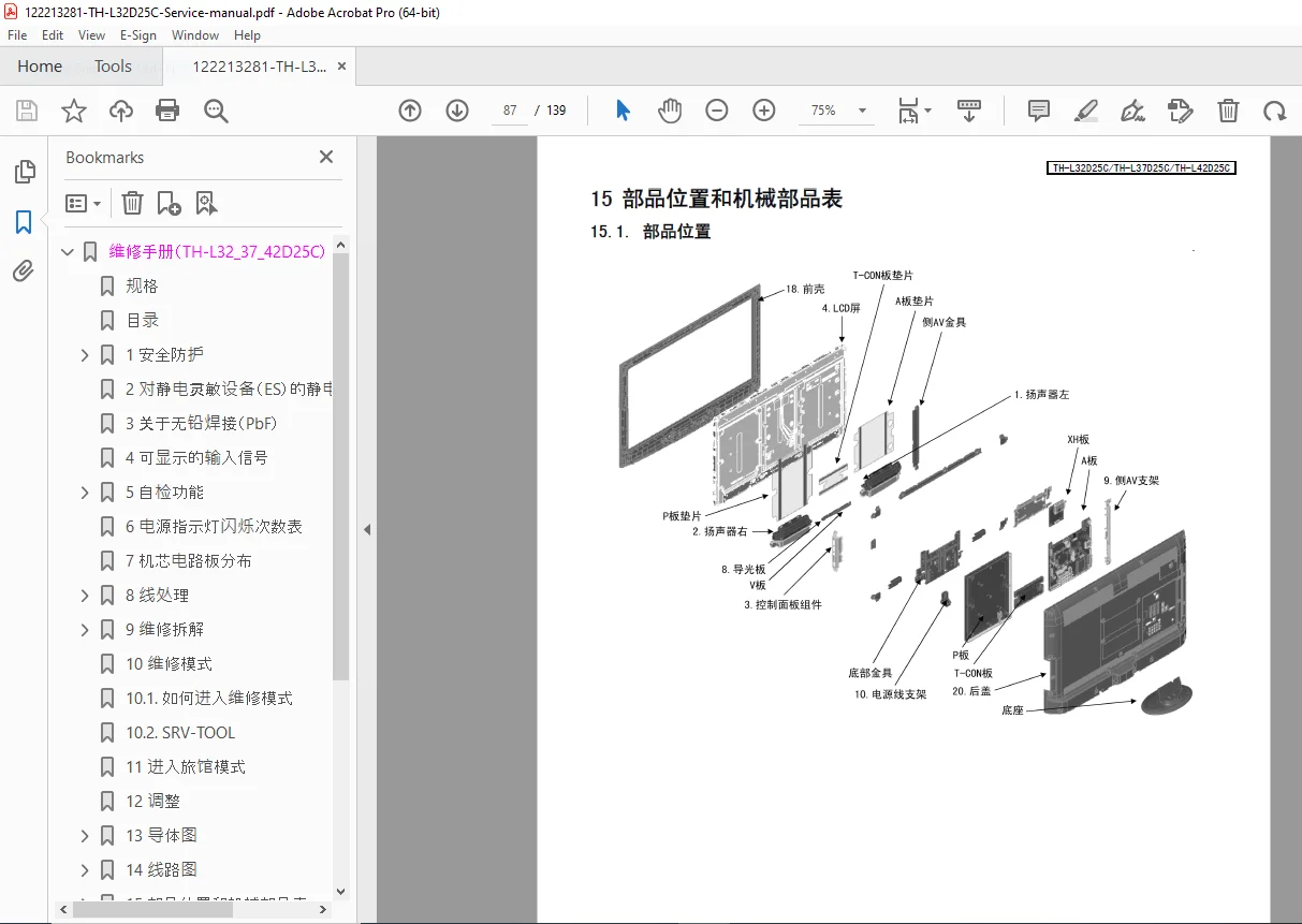
SECTION 7: CHASSIS PCB BOARD DISTRIBUTION (机芯电路板分布)
Page 10
Board Layout and Location:
- A Board (Main Board) location
- T-CON Board (LCD Panel Driver Board) location
- V Board (Inverter Board – if applicable) location
- XH Board location
- P Board location
- Interconnection diagram
- Cable routing reference
SECTION 8: WIRING DIAGRAMS (线处理)
Pages 11-16
Complete Wiring Harness Documentation:
8.1 32″ Wiring Diagram 1 (Page 11)
- Main board connections
- Power supply wiring
- Signal cable routing
8.2 32″ Wiring Diagram 2 (Page 12)
- Display panel connections
- LED backlight wiring
- Control board interfaces
8.3 37″ Wiring Diagram 1 (Page 13)
- 37-inch specific wiring
- Board-to-board connections
8.4 37″ Wiring Diagram 2 (Page 14)
- Extended connection diagrams
- Cable identification
8.5 42″ Wiring Diagram 1 (Page 15)
- 42-inch configuration
- Power distribution
8.6 42″ Wiring Diagram 2 (Page 16)
- Complete wiring harness
- Connector pinouts
SECTION 9: DISASSEMBLY PROCEDURES (维修拆解)
Pages 17-20
Complete Step-by-Step Disassembly:
9.1 Rear Cover Removal (Page 17)
- Screw locations
- Cover removal technique
- Cable access
9.2 Power Cord and Speaker Removal (Page 17)
- Speaker disconnection
- Wire harness routing
- Safe removal procedures
9.3 Control Panel, Power Cord Bracket, Side AV Components, Bottom Bracket (Page 18)
- Control panel removal
- Mounting bracket disassembly
- AV input board access
- Bottom support removal
9.4 XH Board, P Board, A Board, T-CON Board Removal (Page 19)
- Circuit board removal sequence
- Connector disconnection
- Mounting screw locations
- Cable management
9.5 Mounting Brackets, V Board, and Light Guide Plate (Page 20)
- LED backlight access
- Light guide removal
- Reflector sheet handling
9.6 LCD Panel Removal (Page 20)
- LCD panel handling precautions
- LVDS cable disconnection
- Panel support and removal
- Safe storage procedures
SECTION 10: SERVICE MODE (维修模式)
Pages 21-22
10.1 How to Enter Service Mode:
- Button sequence for service menu access
- Remote control method
- Password requirements (if applicable)
- Navigation instructions
10.2 SRV-TOOL:
- Service tool functions
- Parameter adjustment
- Factory settings access
- Calibration procedures
- Data logging
- Firmware information display
SECTION 11: HOTEL MODE (旅馆模式)
Pages 23
11.1 Purpose:
- Hospitality mode features
- User interface restrictions
- Channel locking capabilities
11.2 Method to Enter Hotel Mode Setup Menu:
- Access procedures
- Password system
- Configuration options
11.3 Exiting Hotel Mode:
- Factory reset procedures
- Restoring normal operation
11.4 Hotel Mode Menu Explanation:
- Available settings
- Restriction options
- Volume limiting
- Input blocking
- Menu access control
SECTION 12: ADJUSTMENT PROCEDURES (调整)
Page 24
Voltage Test Points:
12.1 A Board Voltage Test Points:
- Main power supply voltages
- Digital circuit voltages
- Analog circuit voltages
- Signal processor voltages
- Memory power supplies
- Test point locations on PCB
12.2 XH Board Voltage Test Points:
- Board-specific voltage measurements
- Control circuit voltages
- Interface voltages
12.3 T-CON Board Voltage Test Points:
- LCD panel driver voltages
- LVDS signal voltages
- Gamma voltages
- VCOM voltage
- Gate driver supplies
- Source driver supplies
SECTION 13: PCB LAYOUT DIAGRAMS (导体图)
Pages 25-28
Detailed PCB Component Placement:
13.1 A Board (Side A) (Page 25)
- Component placement diagram
- Integrated circuit locations
- Power supply section
- Test point identification
- Connector locations
13.2 A Board (Side B) (Page 26)
- Solder side view
- Trace routing
- Ground plane areas
- Through-hole components
13.3 T-CON Board (Page 27)
- T-CON board layout
- LVDS interface
- Panel connection
- Control ICs
- Buffer amplifiers
13.4 V Board and XH Board (Page 28)
- LED backlight driver (V Board)
- XH board component layout
- Power management section
- Interface circuits
SECTION 14: CIRCUIT DIAGRAMS (线路图)
Pages 29-139
Complete Schematic Diagrams:
14.1 Circuit Diagram Notes (Page 29)
- Schematic reading conventions
- Component designation system
- Signal naming conventions
- Voltage level indicators
- Test point references
T-CON Board Schematics (32-inch):
- 14.2 T-CON Board (1/7) Circuit Diagram (32″) (Page 30)
- 14.3 T-CON Board (2/7) Circuit Diagram (32″) (Page 31)
- 14.4 T-CON Board (3/7) Circuit Diagram (32″) (Page 32)
- 14.5 T-CON Board (4/7) Circuit Diagram (32″) (Page 33)
- 14.6 T-CON Board (5/7) Circuit Diagram (32″) (Page 34)
- 14.7 T-CON Board (6/7) Circuit Diagram (32″) (Page 35)
Additional Circuit Sections Include:
- Main board (A Board) complete schematics
- Power supply circuits
- Video processing circuits
- Audio amplifier circuits
- HDMI interface circuits
- USB interface circuits
- Tuner circuits
- LVDS interface
- LED backlight driver circuits
- Control and microprocessor circuits
- Memory circuits
- Network interface (LAN)
- SD card interface
37-inch and 42-inch Variations:
- Model-specific circuit differences
- Panel interface variations
- Backlight driver modifications
- Power supply adjustments
KEY FEATURES OF PANASONIC TH-L32/37/42D25C:
Display Technology: ✓ Full HD Resolution – 1920×1080 native resolution
✓ 16:9 Widescreen – Modern aspect ratio
✓ LCD Panel – IPS or VA panel technology
✓ LED Backlight – Energy-efficient lighting
✓ High Brightness – Suitable for various lighting conditions
✓ Wide Viewing Angle – Consistent image quality
Connectivity: ✓ Multiple HDMI Inputs – HDMI 1, 2, 3 for HD devices
✓ Component Video – High-quality analog HD input
✓ Composite Video – Standard video inputs (AV1, AV2, AV3)
✓ PC Input – VGA D-sub 15-pin connection
✓ Digital Audio Output – Optical S/PDIF for home theater
✓ USB Ports – Media playback and firmware updates
✓ SD Card Slot – Photo and video playback
✓ Ethernet LAN – Network connectivity
Audio System: ✓ Stereo Speakers – Built-in 14W audio system
✓ Dolby Digital – Digital audio decoding
✓ Headphone Output – Private listening option
✓ Audio Output – Connection to external audio systems
Smart Features: ✓ Multi-Format Support – Various broadcast standards
✓ PC Compatibility – Multiple resolution support
✓ Hotel Mode – Commercial installation features
✓ Energy Efficient – Low standby power consumption
Who Needs This Manual:
✓ Consumer Electronics Repair Technicians servicing Panasonic TVs
✓ LCD TV Repair Specialists working with Panasonic products
✓ Home Theater Installation Technicians performing advanced service
✓ Electronic Service Centers repairing flat panel displays
✓ Hotel/Hospitality Technicians maintaining commercial installations
✓ Independent Repair Shops expanding LCD TV service capabilities
✓ Technical Training Schools teaching flat panel TV repair
✓ Parts Suppliers identifying correct replacement components
✓ Service Companies maintaining rental/lease equipment
✓ Advanced DIY Enthusiasts with electronics repair skills
What Makes This Manual Essential:
- Official Panasonic factory documentation – Authorized service information
- Three model coverage – 32″, 37″, and 42″ in one manual
- 139 comprehensive pages – Complete technical information
- LA02 chassis documentation – Specific to this platform
- Complete circuit schematics – All boards with component-level detail
- Detailed PCB layouts – Component placement diagrams
- Service mode instructions – Advanced diagnostics and adjustments
- LED error code reference – Quick fault diagnosis
- Step-by-step disassembly – Component removal procedures
- Voltage test points – Troubleshooting measurements
- Wiring diagrams – Complete cable routing
Important Language Note:
This service manual is written in Chinese (中文). All text, labels, diagrams, and procedures are in Chinese language. Service technicians should have proficiency in reading technical Chinese or use translation tools. However, the schematic diagrams, PCB layouts, wiring diagrams, and component designations follow international standards and can be understood by experienced technicians regardless of language.
Critical Service Information:
LA02 Chassis Platform:
- Modular board design
- Main board (A Board) with integrated processing
- T-CON board for LCD panel driving
- Separate LED backlight driver (V Board)
- XH board for auxiliary functions
- P board for power management
ESD Precautions:
- Mandatory anti-static procedures
- Wrist strap required
- ESD-safe work surface needed
- Proper component handling
- Storage in anti-static bags
Lead-Free Soldering:
- RoHS compliant components
- Higher temperature requirements
- Special solder and flux needed
- Compatible rework equipment
- PCB heat tolerance considerations
Service Mode Access:
- Advanced diagnostic capabilities
- Factory adjustment procedures
- Calibration tools
- Parameter modification
- Error log access
Troubleshooting Coverage:
Common Issues Addressed:
- No power / standby LED issues
- No picture / blank screen
- No backlight
- Poor picture quality
- Color problems
- No sound / audio distortion
- HDMI connection issues
- USB device not recognized
- Network connectivity problems
- Remote control not responding
- Input switching problems
Diagnostic Tools:
- LED blink code interpretation
- Self-diagnosis function
- Service mode testing
- Voltage measurement procedures
- Signal flow tracing
- Component testing methods
Board-Level Repair:
Main Board (A Board):
- Video processing circuits
- Audio processing
- Tuner interface
- HDMI receivers
- USB controllers
- Network interface
- Memory systems
- Microprocessor
- Power management
T-CON Board:
- LVDS receiver
- LCD panel timing controller
- Gate and source drivers
- Gamma correction
- Panel interface
Power Supply:
- AC-DC conversion
- Multiple voltage rails
- Standby power
- Protection circuits
- Voltage regulation
LED Backlight Driver (V Board):
- LED driver circuits
- Current regulation
- Dimming control
- Protection circuits
Professional Panasonic LCD TV service resource! This official TH-L32/37/42D25C service manual is essential for technicians servicing these Panasonic Full HD LCD televisions. Download instantly and access complete factory schematics, detailed PCB layouts, comprehensive disassembly procedures, service mode instructions, and systematic troubleshooting methods. Repair with confidence using genuine Panasonic specifications and LA02 chassis documentation. Note: This manual is in Chinese language but includes universal schematic diagrams and technical drawings that can be understood by experienced electronics technicians!
Pricing Rationale:
- Official Panasonic factory service manual (139 pages)
- Covers three popular LCD TV models (32″, 37″, 42″)
- Complete schematics and PCB layouts for component-level repair
- LA02 chassis specific documentation
- Chinese language manual (affects pricing – more niche market)
- Target audience: consumer electronics technicians, LCD repair specialists
- Essential for out-of-warranty repairs
- Comprehensive technical content despite language barrier
- Schematic diagrams are language-independent
- Professional-grade service documentation