Perkins 1200F Models MT, MU, MV, MW, BM and BN Series ELECTRONIC APPLICATION & INSTALLATION MANUAL – PDF DOWNLOAD
Original price was: $59.95.$23.95Current price is: $23.95.
Perkins 1200F Models MT, MU, MV, MW, BM and BN Series ELECTRONIC APPLICATION & INSTALLATION MANUAL
MODELS COVERED:
1204F-E44TA
1204F-E44TTA
1206F-E70TA
1206F-E70TTA
Description
Perkins 1200F Models MT, MU, MV, MW, BM and BN Series ELECTRONIC APPLICATION & INSTALLATION MANUAL
TABLE OF CONTENTS:
Perkins 1200F Models MT, MU, MV, MW, BM and BN Series ELECTRONIC APPLICATION & INSTALLATION MANUAL
CONTENTS
10 SAFETY 9
11 WARNING – WELDING 9
112 Warning – Electrostatic Paint Spraying 9
113 Warning – Jump Starting 10
20 ENGINE & AFTERTREATMENT COMPONENT OVERVIEW 11
21 MAIN ENGINE SENSOR AND ACTUATOR DETAIL 11
211 Electronic Control Module 11
212 Fuel System 11
213 Engine Speed 12
214 NRS (NOx Reduction System) 12
215 Core Engine System 12
216 Air System 13
217 Emissions System Assist Devices 13
22 AFTERTREATMENT SYSTEM SENSOR & ACTUATOR DETAILS 13
221 PM Capture Devices 13
223 Selective Catalytic Reduction (SCR) Technologies 14
23 SYSTEM COMPONENT DIAGRAMS & SCHEMATICS 15
231 1204F Engine and Aftertreatment Layout 15
232 1206F Engine and Aftertreatment Layout 18
24 ENGINE & AFTERTREATMENT COMPONENT LAYOUT DIAGRAMS 20
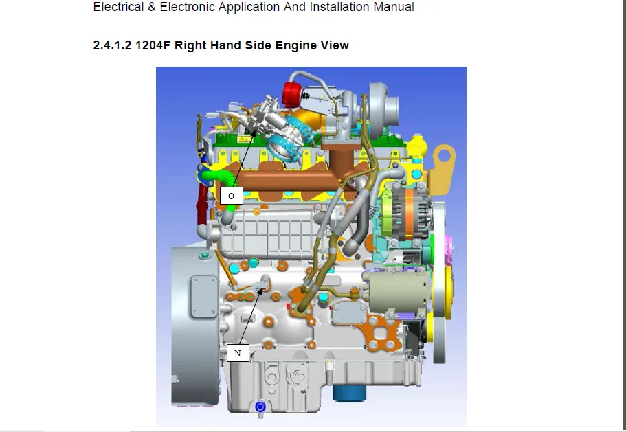
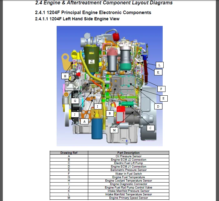
241 1204F Principal Engine Electronic Components 20
242 1206F Principal Engine Electronic Components 23
243 1204F AT Principal Components 26
244 1206F AT Principal Components 27
30 CUSTOMER SYSTEM OVERVIEW KEY ELEMENTS 28
31 AFTERTREATMENT CONFIGURATIONS 28
32 TIER 4F MANDATORY INSTALL COMPONENTS 28
33 OPTIONAL CUSTOMER INSTALLED COMPONENTS 29
40 POWER & GROUNDING CONSIDERATIONS 30
41 SYSTEM GROUNDING 30
411 Ground Stud On Starter Motor 30
412 Engine Block Ground Connection 30
413 Aftertreatment System Grounding 31
42 SYSTEM VOLTAGE & CURRENT REQUIREMENTS 32
421 Engine ECM 32
422 1204F DEF System 32
423 1206F DEF System 33
424 System Effect on Alternator Specification 33
43 ECM POWER SUPPLY & CIRCUIT RESISTANCE 34
431 Important Voltage Supply Circuit Considerations 36
432 Battery (+) Connection 36
433 Battery (-) Connection 38
434 Correct method of ECM battery connection 39
435 Incorrect method of ECM battery connection 39
44 ENGINE ECM POWER SUPPLY CIRCUIT RESISTANCE TEST 40
441 Test Procedure 40
45 DEF SYSTEM POWER SUPPLY 42
451 1204F DEF System Power Supply connection 42
452 1206F DEF System Power Supply Connection 43
46 SUPPRESSION OF VOLTAGE TRANSIENTS 44
461 Suppression Methods & Best Practice 44
47 DIRECT BATTERY CONNECTION REQUIREMENTS 45
48 POWERING THE ENGINE ECM VIA AUXILIARY POWER SUPPLIES 46
49 SENSOR COMMON CONNECTIONS 46
Electrical & Electronic Application And Installation Manual
Production Release Version 10
Page 3
491 Actuator Driver Return 46
492 Analogue Sensor Return 46
493 Switch Return 47
494 Digital Return 47
50 CONNECTORS & WIRING HARNESS REQUIREMENTS 48
51 ENGINE ECM J1 CONNECTOR 48
511 J1 Connector Layout 48
512 Tightening The OEM Connector 49
513 ECM Connector Wire Gauge Sealing Capability 49
514 Hand Crimping For Prototype machines and Low Volume Production: 49
515 ECM connector sealing plug installation guidelines 49
516 OEM harness Dress Cover With Integrated Strain Relief 49
517 Machine Crimping For High Volume Production 50
52 ENGINE ECM J1 CONNECTOR I/O 50
53 ECM CONNECTOR ASSEMBLY & DISASSEMBLY 53
531 Connector Assembly 53
532 Connector Disassembly 55
54 DIAGNOSTIC CONNECTOR 56
541 Diagnostic Connector Layout 56
542 Diagnostic Connector Wire Gauge Size 56
543 Pin Information 57
55 MANDATORY ENGINE & AFTERTREATMENT CONNECTORS 58
56 CONNECTOR TERMINAL CONTACTS 58
57 WIRE SPECIFICATION REQUIREMENTS 58
571 Wire Thickness Overview 59
58 HARNESS WIRING STANDARDS 60
581 Connectors 60
582 Harness Bends Near Connectors 61
583 Cable routing 61
584 Electromagnetic Compatibility (EMC) 62
585 Insulation Selection and Thermal Protection 62
60 CUSTOMER CONNECTION OF ENGINE COMPONENTS 63
61 WATER IN FUEL SWITCH 63
611 WIF Switch Operation 63
612 WIF Switch Configuration 63
613 WIF Switch Installation 64
62 AMBIENT AIR TEMPERATURE SENSOR 64
621 Ambient Air Temperature Sensor Operation 64
622 Ambient Air Temperature Sensor Configuration 65
623 Ambient Air Temperature Sensor Installation 65
63 ENGINE ELECTRICAL FUEL LIFT PUMP 66
631 Engine Electrical Fuel Lift Pump Operation 66
632 Engine Electrical Fuel Lift Pump Configuration 66
633 Engine Electrical Fuel Lift Pump Installation 66
70 1204F CONNECTING TO THE ENGINE AFTERTREATMENT 70
71 DOC + DPF + SCR 70
711 System Architecture 70
712 Electrical Connections 71
713 Component I/O 72
72 DOC + SCR 74
721 System Architecture 74
722 Electrical Connections 74
723 Component I/O 76
73 1204F DEF SYSTEM 77
731 System Architecture 77
732 PEU Electrical Connections & Component Installation Requirements 78
Electrical & Electronic Application And Installation Manual
Production Release Version 10
Page 4
733 Component I/O 84
74 1204F AFTERTREATMENT WIRING SCHEMATICS 86
741 1204F DOC & SCR Schematic 86
742 1204F DOC, DPF & SCR Schematic 87
80 1206F CONNECTING TO THE ENGINE AFTERTREATMENT 88
81 IG CEM 88
811 System Architecture 88
812 IG CEM Electrical Connections 90
813 Component I/O 91
82 1206F PUMP ELECTRONICS & TANK UNIT (PETU) 93
821 PETU System Architecture 93
822 PETU Electrical Connections & Component Installation Requirements 94
823 Component I/O 100
83 1206F AFTERTREATMENT WIRING SCHEMATIC 101
90 COMPONENT INSTALLATION REQUIREMENTS 102
91 DPF SOOT SENSOR 102
911 DPF Soot Sensor Operation 102
912 DPF Soot Sensor Configuration 102
913 DPF Soot Sensor Installation 102
92 NOX SENSOR 106
921 NOx Sensor Operation 106
922 NOx Sensor Configuration 107
923 NOx Sensor Installation 107
93 AMMONIA (NH3)SENSOR 110
931 Ammonia (NH3) Sensor Operation 110
932 Ammonia (NH3) Sensor Configuration 111
933 Ammonia (NH3) Sensor Installation 111
94 DPF IN AND SCR PERKINSIN COMBINED TEMP SENSOR (1206F) 114
941 DPF & SCR Temp Sensor Operation 114
942 DPF & SCR Temp Sensor Configuration 114
943 DPF & SCR Temp Sensor Installation 115
95 IG CEM ID MODULE 116
951 IG CEM ID Module Operation 116
952 IG CEM ID Module Configuration 116
953 IG CEM ID Module Installation 116
96 DOC, DPF & SCR INLET TEMPERATURE SENSORS (1204F) 120
961 DOC, DPF & SCR Inlet Temperature Sensor Operation 120
962 DOC, DPF & SCR Inlet Temperature Sensor Configuration 120
963 DOC, DPF & SCR Inlet Temperature Sensor Installation 120
100 STARTING AND STOPPING THE ENGINE 123
101 STARTING THE ENGINE 123
102 STOPPING THE ENGINE (AND PREVENTING RESTART) 124
1021 Ignition Keyswitch 124
1022 Battery Isolation Switches 125
1023 User Defined Shutdown Switch (Remote Shutdown) 126
1024 Delayed Engine Shutdown (1206F Only) 127
1024 Intake Air Shutoff Valve 127
1025 Overspeed Verify Switch 128
1026 Datalink stops 128
1027 Engine Emergency Stops 129
1028 Common problems with the application of stop devices 129
110 ENGINE SPEED DEMAND 130
111 ANALOGUE SENSOR 131
1111 Analogue Sensor Operation 131
1112 Analogue Sensor Configuration 131
Electrical & Electronic Application And Installation Manual
Production Release Version 10
Page 5
1113 Analogue Sensor Installation 132
1114 Evaluating Component Compatibility (Testing) 132
112 PWM SENSOR – COMPATIBILITY 135
1121 PWM Sensor Operation 135
1122 PWM Sensor Configuration 136
1123 PWM Sensor Installation 136
113 THROTTLE LOCK (PTO MODE) 137
1131 Throttle Lock Mode Operation 137
1132 Throttle Lock Mode Configuration 141
1133 Throttle Lock Mode Installation 141
1134 Throttle Lock Operation Under Engine Load 141
114 MULTI POSITION THROTTLE SWITCH (MPTS) 142
1141 MPTS Operation 142
1142 MPTS Configuration 143
1143 MPTS Installation 144
115 TORQUE SPEED CONTROL TSC1 (SPEED CONTROL OVER CAN) 144
116 ARBITRATION OF SPEED DEMAND 144
1161 Manual Throttle Selection Switch 145
117 ACCELERATION AND DECELERATION RAMP RATES 145
118 THROTTLE BEHAVIOUR DURING ENGINE GOVERNOR CHANGES 145
119 ENGINE LIMP HOME SPEED 146
1110 THROTTLE CALIBRATION 146
11101 Throttle Parameter Description 148
11102 Throttle Calibration Function 150
11103 Idle Validation Switch 154
1111 DEFINITION OF ENGINE SPEED POINTS 155
11111 Engine Low Idle 156
11112 Engine High Idle 156
11113 Engine Rated Speed 157
120 COLD WEATHER ENGINE OPERATION & STARTING AIDS 158
121 CONTROL OF GLOW PLUGS BY THE ENGINE ECM 160
1211 Glow Plug System Operation 160
1212 Glow Plug System Configuration 162
1213 Glow Plug System Installation 162
122 ETHER COLD START SYSTEMS 164
1221 Ether start Operation 164
1222 Ether start Configuration 164
1223 Ether start Installation 164
123 HEATED BREATHER 167
1231 Heated Breather Operation 167
1232 Heated Breather Configuration 167
1233 Heated Breather Installation 168
124 COLD WEATHER REGENERATION AID 168
1241 Cold Weather Regeneration Aid Operation 168
1242 Cold Weather Regeneration Aid Configuration 169
1243 Cold Weather Regeneration Aid Installation 169
125 EXTREME LOW TEMPERATURE AFTERTREATMENT AMBIENT AIR TEMPERATURE SENSOR 169
1251 Aftertreatment Ambient Air Temperature Sensor Operation 169
1252 Aftertreatment Ambient Air Temp Sensor Configuration 169
1253 Aftertreatment Ambient Air Temp Sensor Installation 170
126 ENGINE SOFT START PROTECTION 171
1261 Engine Soft Start Protection Operation 171
1262 Engine Soft Start Protection Configuration 171
1263 Engine Soft Start Protection Installation 171
130 OPERATOR INDICATORS & FAULT DISPLAYS 173
131 ENGINE & AT DIAGNOSTIC SYSTEMS 173
1311 Monitoring System Fault Status Levels 174
132 GAUGE DRIVERS 175
Electrical & Electronic Application And Installation Manual
Production Release Version 10
Page 6
1321 Datalink Driven Intelligent Displays 175
1322 Minimum Functional Specification for J1939 display 175
133 LAMP OUTPUTS & OPERATION 176
1331 Hardwired Lamp Outputs 176
1332 J1939 Indicator Support 176
1333 Indicator ISO Reference Symbols 177
1334 Engine Shutdown Indicator 178
1335 Engine Warning Indicator 178
1336 Engine Wait To Start Indicator 179
1337 Oil Pressure Indicator 180
1338 Emissions System Malfunction Indicator 180
1339 Low DEF Level Indicator 181
13310 Wait To Disconnect Indicator 182
13311 Delayed Engine Shutdown Active Indicator (1206F Only) 182
140 ENGINE & AFTERTREATMENT MONITORING SYSTEM 183
141 GENERAL INFORMATION 184
1411 Monitoring Levels 184
1412 Parameter Severity Levels 185
1413 Monitoring System Example 186
142 NON EMISSIONS CRITICAL COMPONENT MONITORING & PROTECTION 187
1421 Coolant Temperature 187
1422 Engine Oil Pressure 188
1423 Intake Manifold Temperature 189
1424 Engine Overspeed 190
1425 High NRS Temperature 191
143 EMISSIONS CRITICAL COMPONENTS MONITORING & PROTECTION 192
1431 Inducement Strategy High Level Overview 192
1432 Combined EU/EPA Inducement Strategy Operation 192
1433 Combined EU/EPA Inducement Strategy Configuration 197
1434 Repeat Occurrence and Final Inducement Handling 198
1435 Final Inducement Safe Harbor Mode 199
1436 Engine First Fit Inducement Activation 199
1437 Emergency Inducement Override Strategy 199
150 MONITORED INPUTS FOR CUSTOMER FITTED SENSORS 200
151 AIR FILTER SERVICE INDICATOR – AIR INTAKE RESTRICTION SWITCH 200
1511 Air Intake Restriction Switch Operation 200
1512 Air Intake Restriction Switch Configuration 201
1513 Air Intake Restriction Switch Installation 201
152 COOLANT LEVEL SWITCH 202
1521 Coolant Level Switch Operation 202
1522 Coolant Level Switch Configuration 202
1523 Coolant Level Switch Installation 203
153 AUXILIARY TEMPERATURE SENSOR 203
1531 Auxiliary Temperature Sensor Operation 203
1542 Auxiliary Temperature Sensor Configuration 204
1543 Auxiliary temperature Sensor Installation 204
155 AUXILIARY PRESSURE SENSOR 206
1551 Auxiliary Pressure Sensor Operation 206
1552 Auxiliary Pressure Sensor Configuration 206
1553 Auxiliary pressure Sensor Installation 206
160 AFTERTREATMENT SYSTEM MACHINE INTEGRATION 208
161 AFTERTREATMENT SYSTEM OPERATION 208
1611 DOC Operation 208
1612 DPF Operation 208
1613 SCR Operation 208
162 LOW TEMPERATURE AFTERTREATMENT REGENERATION SYSTEM 208
Electrical & Electronic Application And Installation Manual
Production Release Version 10
Page 7
1621 Low Speed Regeneration 1204F DOC + SCR only 208
1632 Low Temperature Regeneration 1204F & 1206F DOC, DPF + SCR Products 209
162 DEF SYSTEM OPERATION 211
163 DEF SYSTEM MACHINE INTERFACE REQUIREMENTS 214
1631 Delayed Engine Shutdown (1206F Only) 214
1632 System Purge 219
1633 DEF Thaw 225
1634 Operator Indicators and Displays 225
170 ENGINE GOVERNOR 227
171 MIN / MAX GOVERNING 227
1711 Min / Max Governing Operation 227
1712 Min / Max Governing Configuration 228
1713 Min / Max Governing Installation 228
172 ENGINE ALL SPEED GOVERNING 228
1721 Engine All Speed Governing Operation 228
1723 Engine All Speed Governing Configuration 230
1723 Engine All Speed Governing Installation 231
173 RATING SELECTION USING EST 231
174 ENGINE HIGH SPEED GOVERNOR (GOVERNOR RUN-OUT) 231
1741 Engine High Speed Governor Operation 231
1742 Engine High Speed Governor Configuration 232
175 MODE SELECTION 232
1751 Mode Selection Operation 232
1752 Mode Selection Configuration 233
1753 Installation 233
1754 Rating and Droop changes requested via the J1939 datalink 233
180 DATALINK SUPPORT 234
181 SAE J1939 234
1811 Summary of Key J1939 Application Issues 234
1812 Physical layer 234
1813 Network Layer 235
1814 Application Layer 235
182 CONNECTION AND USE OF THE J1939 CAN BUS 236
190 J1939 SUPPORTED PARAMETERS QUICK REFERENCE 238
200 J1939 PARAMETERS – DETAILED DESCRIPTIONS 247
201 SENDING MESSAGES TO THE ENGINE ECM 247
2011 Source Addressing 247
2012 Destination Addressing 247
202 J1939 SECTION 71 – TSC1 OPERATION 248
2021 Torque Speed Control (TSC1) Operating Principles 248
2022 Torque Speed Control (TSC1) Message Configuration & Control 250
APPENDIX 252
APPENDIX 1 COMPLETE SYSTEM CONNECTOR LISTS 252
1204F Connector Parts List 252
1206F Connector Parts List 254
DESCRIPTION:
Perkins 1200F Models MT, MU, MV, MW, BM and BN Series ELECTRONIC APPLICATION & INSTALLATION MANUAL
PREFACE:
Electrical & Electronic Application And Installation Manual:
- The information contained in this manual is confidential and proprietary to Perkins. It is intended for circulation only to Perkins employees, or to employees of OEMs intending to purchase and install Tier 4 Final/EU Stage IV Perkins engines in their equipment.
- Distribution of this material must be limited to personnel whose duties require knowledge of such material and is intended exclusively for their information and training. Distribution of this material for other purposes is strictly prohibited.
- A&I Manual Introduction This manual has been compiled to explain mandatory requirements, provide information for designers, and provide information on the application and installation of the 1204F-1206F engines into industrial equipment, to meet U.S. Environmental Protection Agency (EPA) Tier 4 Final and European Union (EU) Stage IV emission standards.
Serial number prefixes for the engines referenced in this manual are:
1204F : MT, MU, MW & MV
1206F : BM & BN
The following media publications for the relevant engine type should also be used for further technical information:
• 1204F-1206F Application and Installation Manual TPD1830
• 1204F DEF System Supplement TPD1832
• 1206F DEF System Supplement TPD1834
• Operator and Maintenance Manual (OMM)
• System Operation Test and Adjust (SOTA)
• Disassembly and Assembly (D&A)
• Engine Specification Manual (ESM)
PERKINS 1200F MODELS MT, MU, MV, MW, BM AND BN SERIES ELECTRONIC APPLICATION & INSTALLATION MANUAL – PDF DOWNLOAD:
IMAGES PREVIEW OF THE MANUAL:
PLEASE NOTE:
- This is not a physical manual but a digital manual – meaning no physical copy will be couriered to you. The manual can be yours in the next 2 mins as once you make the payment, you will be directed to the download page IMMEDIATELY.
- This is the same manual used by the dealers inorder to diagnose your vehicle of its faults.
- Require some other service manual or have any queries: please WRITE to us at [email protected]
Maddox Carson –