
Perkins 1500 1700 2000 Series ElectropaK Electronic Application & Installation Manual TPD1970
Original price was: $34.95.$19.95Current price is: $19.95.
Perkins 1500/1700/2000 Series ElectropaK Electronic Application & Installation Manual TPD1970 Issue 8. Covers ECM, wiring harness, J1939 data link, engine monitoring, speed control, and installation procedures for 1506, 1706, 2206, 2506, and 2806 engines in electric power applications.
Description
Perkins 1500/1700/2000 Series ElectropaK Electronic Application & Installation Manual
This Perkins 1500/1700/2000 Series ElectropaK Electronic Application & Installation Manual (Publication TPD1970, Production Issue 8, August 2020) is the complete guide for integrating Perkins 1500, 1700, and 2000 Series electronic engines into electric power applications. Written for original equipment manufacturers and installation engineers, it covers every aspect of the electronic engine control system, from ECM pinouts and wiring harness design to J1939 data link configuration, engine monitoring, and speed control. Whether you are building a new genset or retrofitting an existing installation, this Perkins ElectropaK installation manual gives you the technical detail needed to get the job done right.
File Details
- Manual Type: Electronic Application & Installation Manual
- Brand: Perkins
- Models Covered: 1506, 1706, 2206, 2506, 2806 Series
- Engine Types: 1506A/C-E88TAG1-5, 1706A-E93TAG1-2, 1706D-E93TAG1-2, 2206A/C/D-E13TAG2-6, 2506A/C/D-E15TAG1-4, 2806A/C-E18TAG1-3, 2806A-E18TTAG4-7, 2806C-E18TTAG6-7
- Language: English
- Page Count: 144
- File Format: PDF
- Document Number: TPD1970
- Edition/Revision: Production Issue 8
- Date: August 2020
Chapters Covered
- 1.0 Introduction and Purpose — Warning, Welding, Replacement Parts, Terminology
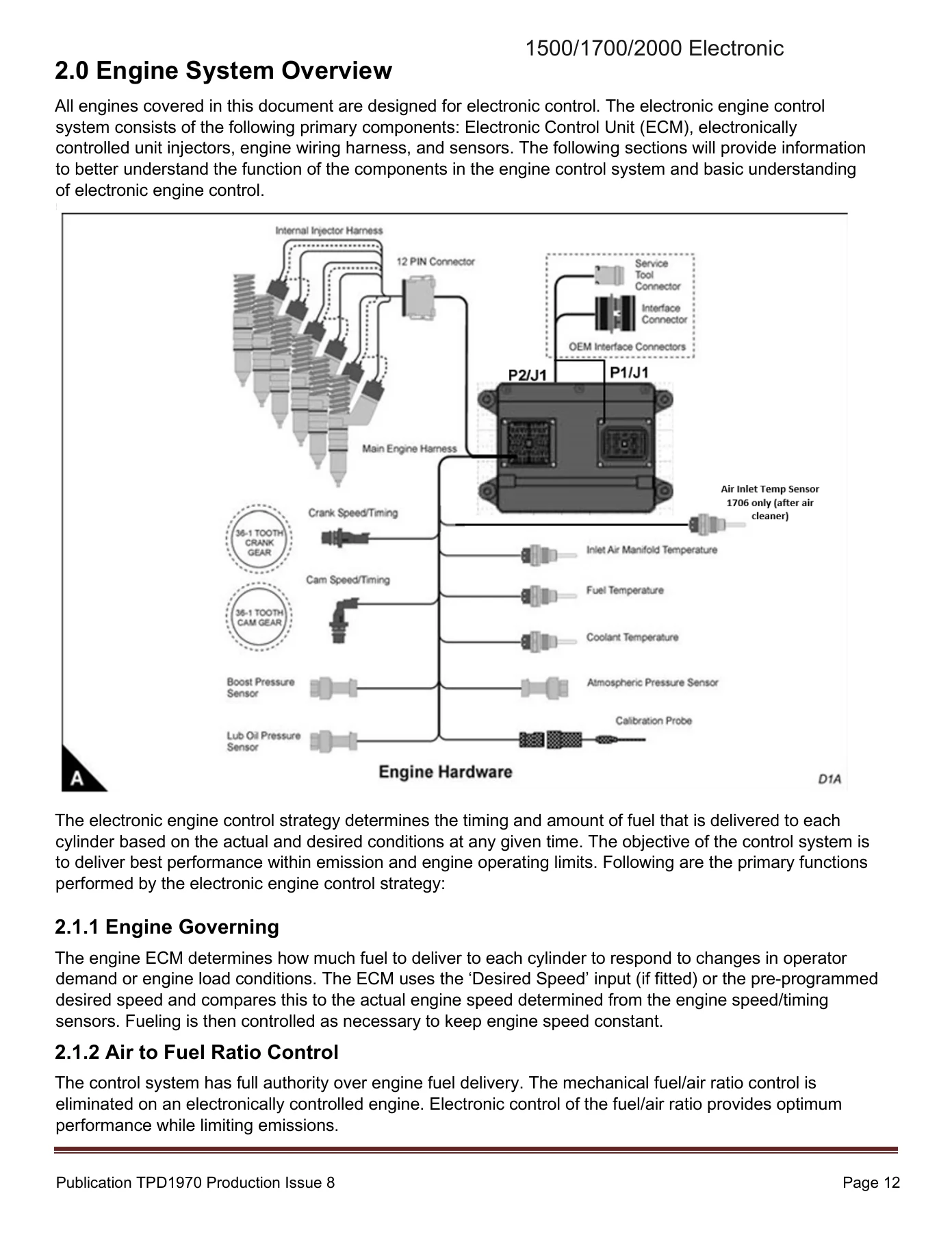
- 2.0 Engine System Overview — Engine Governing, Air to Fuel Ratio Control, Injection Timing Control, Cold Starting Strategy, Engine Protection and Monitoring, Factory Configuration Parameters, Engine Component Overview, Engine System Diagrams
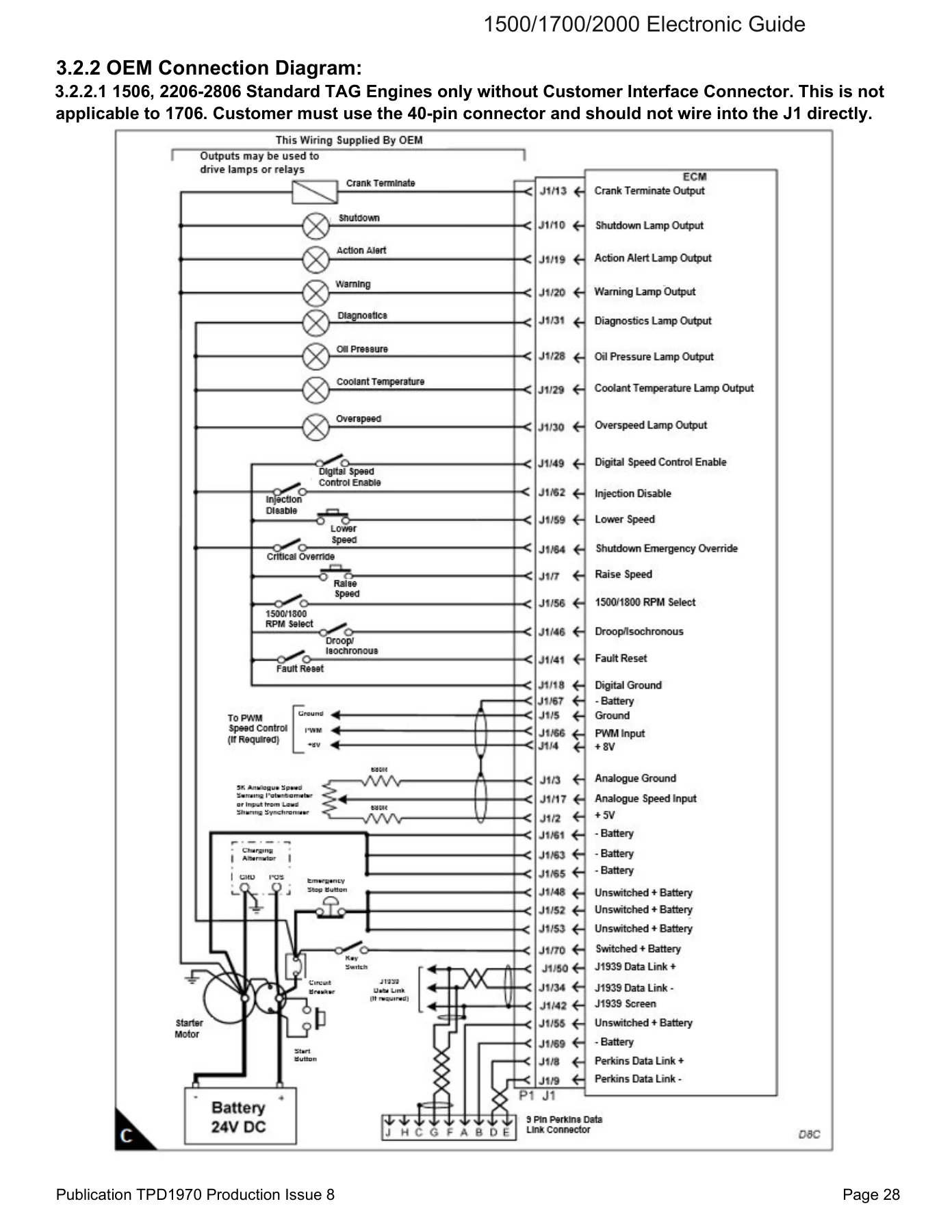
- 3.0 Customer System Overview — Customer Configuration Parameters, Customer Component Overview, Customer Installed Components Diagram, OEM Connection Diagram, Application Wiring Schematic, Speed Control Hardware, Digital Inputs, Digital Outputs, Customer Optional Components
- 4.0 Power and Grounding Considerations — Power Requirements, System Voltage, Battery (+) Connection, Circuit Protection, Engine Grounding, Recommended Power Supply Wiring, ECM Battery (-) Connections, Engine Ground Stud to Vehicle Battery Ground, Air Starter Equipped Vehicles, Sensor Common Connections, Suppression of Voltage Transients, Battery Disconnect Switch
- 5.0 Connectors and Wiring Harness Requirements — Wiring Harness Components, Deutsch DT Connector, Deutsch HD-10 Connectors, Deutsch DRC/AEC Connector, 1500/2000 Series A4 ECM 70-Pin Connector, Connector Terminal Contacts, Wire Type and Gauge Size, Connector Seal Plug, Wiring Harness Design, Harness Routing, Maintenance Considerations, Harness Bends, Sealing Splices and Ring Terminals, Wire Connection Guidelines, ECM Guards, Customer Supplied Service Tool Connector (J66) Wiring, SAE J1939/11 Data Bus Wiring
- 6.0 Customer Equipment I.D. and Passwords — Equipment Identification, Customer Passwords
- 7.0 Factory Configured Parameters — Engine Serial Number, Rating Number, FLS (Full Load Setting), FTS (Full Torque Setting)
- 8.0 Stopping the Engine — Auxiliary Engine Shutdown Switch, J1939 Engine Shutdown, Emergency Shutdown
- 9.0 Engine Speed Demand — PWM Speed Control, Analogue Speed Control Input, Digital Speed Control, J1939 Speed Control (TSC1), EST Override (Dyno Test Mode), Low Idle Speed, Engine Acceleration Rate
- 10.0 Load Calculations — Load Factor, Percent Load
- 11.0 Engine Monitoring and Protection — Engine Monitoring Parameters, Oil Pressure, Coolant Temperature, Engine Speed, Inlet Air Temperature, Fuel Temperature Monitoring, Fuel Pressure, Altitude (Exhaust Temperature), Boost Pressure, Engine Monitoring Lamps, Diagnostic Lamp
- 12.0 Data Link Support — SAE J1939, Perkins Data Link, Other Data Link Standards
- Appendix A 1.0 ECM Interface Requirements — PWM Input, Switch to Ground Input, High-Side Current Driver (2 A) Output, Low-Side Current Driver (300 mA) Output
- Appendix A 2.0 ECM Connector (J1/P1) Pinout Table — 1506/2206/2506/Standard 2806 (TAG), Power Density 2806 Model (TTAG), 1706A/D Model
- Appendix A 3.0 Customer Configuration Parameter Table — 1506, 1706 EP LRC, 2000 Series (non-PD), 2806 PD TTAG
- Appendix A 4.0 Customer Parameter Worksheet
- Appendix A 5.0 Engine Monitoring System Parameter Table — 1506, 1706, Standard TAG (2206-2806), Power Density 2806 E18TTAG4-7
- Appendix A 6.0 Switch Specifications
- Appendix A 7.0 Installation Checklist
- Appendix A 8.0 Reference Media Numbers
- Appendix A 9.0 Issue Change Summary
This Perkins ElectropaK manual is not a generic engine service guide — it is a dedicated installation manual for the electronic control systems used across the 1500, 1700, and 2000 Series engine families. It walks through the ECM hardware, sensor packages, fuel systems (including HEUI, MEUI, and common rail variants), and the wiring and grounding practices that keep them reliable. The document explains how the ECM governs engine speed, controls air-to-fuel ratio, manages injection timing, and executes cold starting strategies, then shows how those functions are configured and monitored through Perkins EST. For OEMs and installers, the OEM connection diagrams, application wiring schematics, and customer interface connector pinouts are essential reference material for building a harness that works the first time.
What This Manual Helps You Do
The Perkins 1500/1700/2000 Series ElectropaK Electronic Application & Installation Manual gives you the technical foundation to:
- Design and build a customer harness that interfaces correctly with the engine ECM, including the 70-pin A4 ECM connector, 40-pin customer connector, and 8-pin connector used on Power Density engines.
- Configure ECM parameters for speed control, engine monitoring, protection thresholds, and data link communication.
- Wire and troubleshoot digital inputs and outputs for warning lamps, shutdown lamps, action alert lamps, starter relays, and auxiliary shutdown switches.
- Set up SAE J1939 data links with proper termination, shielding, and stub length, and understand the supported PGNs for engine control and diagnostics.
- Interpret engine monitoring parameters for oil pressure, coolant temperature, engine speed, inlet air temperature, fuel temperature, fuel pressure, altitude derate, and boost pressure.
- Follow installation checklists for battery connections, grounding, circuit protection, harness routing, and suppression of voltage transients.
Every section is written for the installer who needs to get the electrical and electronic systems right the first time. The wiring diagrams, pinout tables, and configuration parameter tables are laid out clearly, and the appendix includes a full installation checklist that helps prevent common start-up issues. If you are commissioning, servicing, or retrofitting a Perkins 1506, 1706, 2206, 2506, or 2806 engine in a genset or electric power application, this manual is the reference that ties the electronic control system together.
Why This Manual Matters
Electronic engines are only as reliable as their installation. A harness built to the wrong spec, a ground path that introduces noise, or an incorrectly configured ECM parameter can cause hard starting, intermittent shutdowns, or diagnostic faults that are difficult to trace. This Perkins ElectropaK installation manual exists to eliminate those problems by giving you the exact wiring requirements, connector part numbers, wire gauge selections, and configuration options that Perkins specifies. It covers the subtle details — like keeping the key switch wired directly to battery positive through a circuit breaker, using gold-plated sockets in the ECM connector, and maintaining the correct bend radius near connectors — that make the difference between a clean installation and a troubleshooting nightmare.
IMAGES PREVIEW
Instant PDF Delivery
This Perkins 1500/1700/2000 Series ElectropaK Electronic Application & Installation Manual is delivered as an instant PDF download. No shipping, no waiting. You can view it on any device, print the pages you need for the shop, and keep the full manual on hand for reference. Whether you are working on a single engine or supporting a fleet, having the complete TPD1970 Issue 8 manual available immediately means you can start the job without delay.


Reviews
There are no reviews yet.