
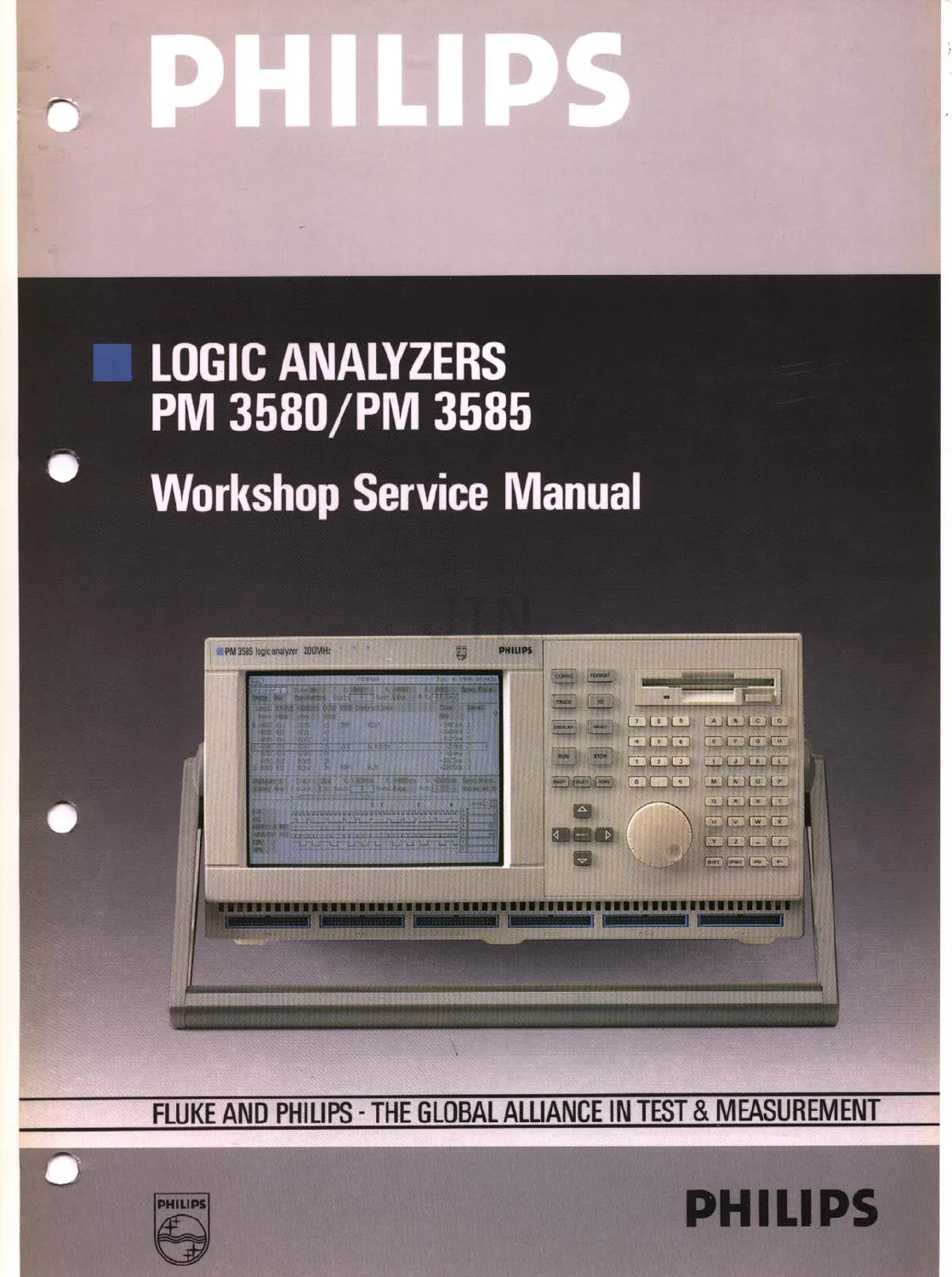
Philips PM 3580 PM 3585 Logic Analyzer Workshop Service Manual PDF Download
Original price was: $29.95.$18.95Current price is: $18.95.
150-page workshop service manual for Philips PM 3580 and PM 3585 State and Timing Logic Analyzers, covering dismantling, mainframe circuitry, adjustments, adaptors, extensive diagnostic testing and corrective-maintenance guidance. Instant PDF download.
Description
Philips PM 3580 / PM 3585 Logic Analyzer Workshop Service Manual
This 150-page workshop service manual covers the Philips PM 3580 and PM 3585 family of State and Timing Logic Analyzers. It provides detailed servicing information for dismantling, mainframe hardware, power supply and display circuitry, adjustments, adaptor interfaces, built-in diagnostics and fault-isolation procedures. The supplied PDF contains Chapters 1 through 6 and the opening portion of Chapter 7, ending in the Corrective Maintenance section.
Models and Configurations Covered
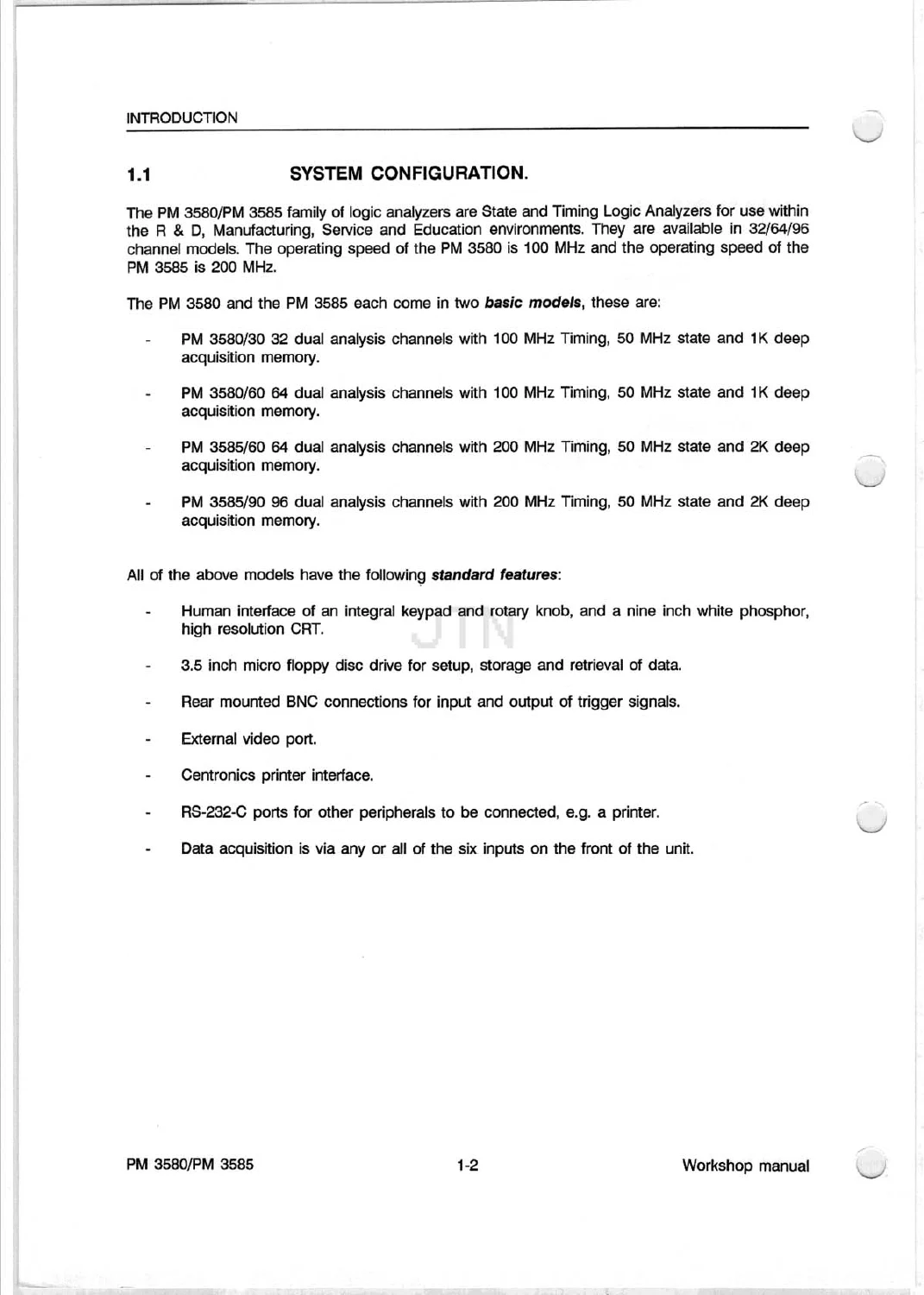
- PM 3580/30 — 32 dual analysis channels, 100 MHz timing, 50 MHz state and 1K deep acquisition memory.
- PM 3580/60 — 64 dual analysis channels, 100 MHz timing, 50 MHz state and 1K deep acquisition memory.
- PM 3585/60 — 64 dual analysis channels, 200 MHz timing, 50 MHz state and 2K deep acquisition memory.
- PM 3585/90 — 96 dual analysis channels, 200 MHz timing, 50 MHz state and 2K deep acquisition memory.
The PM 3580 and PM 3585 family is shown with features including an integral keypad and rotary knob, 3.5-inch micro floppy disk drive, rear-mounted BNC trigger connections, external video port, Centronics printer interface, RS-232-C ports and front-panel data-acquisition inputs.
Main Systems and Subjects Included
- General information, safety instructions and system configuration
- Peripheral equipment and analyser accessories
- Mains-voltage setting and instrument access procedures
- Rear access plate, instrument sleeve and handle removal
- Disk-drive and keyboard assemblies
- Main-board removal and hardware description
- Power-supply unit and fan assembly servicing
- Visual display unit and CRT-related servicing procedures
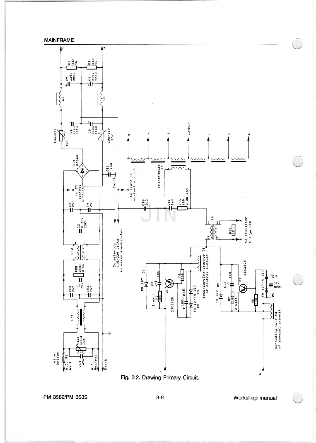
- Power-supply circuitry, block diagrams and protection functions
- Floppy-disk drive, keyboard and video-monitor sections
- Main-board CPU, acquisition and peripheral circuitry
- Adjustment procedures and jumper settings
- Timing and microprocessor adaptor information
- Diagnostic tests and fault-report interpretation
- Corrective-maintenance replacement guidance
Diagnostic and Service Coverage
A major portion of the manual is dedicated to diagnostic testing. It explains the Power On Self Test and service diagnostic diskette procedures, together with tests for the stack, ROM, RAM, floppy controller and Multi-Function Peripheral.
- Dynamic and static RAM testing
- EPROM checksum testing
- Video Controller Test
- 68070 timer testing
- Keyboard testing
- RS-232 connector loop-back testing
- Centronics interface testing
- Floppy-controller testing
- Multi-Function Peripheral testing
- Boundary Scan Test operation
- Error-vector, probability, pinning and diagnostic reports
Why This Manual Is Useful
This manual gives technicians a structured path from safe instrument disassembly through circuit-level understanding and built-in diagnostic testing. The detailed diagrams, assembly procedures, test routines and error-report explanations are particularly useful when locating faults in the PM 3580/PM 3585 mainframe, memory, interfaces, display, power supply and associated logic circuitry.
PDF coverage note: the supplied 150-page file ends at Chapter 7, section 7.1.4, Static Sensitive Components. Later chapters shown in the front table of contents are not present in this PDF.
Instant PDF Download
Delivered as a digital PDF for immediate access after payment. View it on a computer, tablet or other PDF-compatible device whenever you need the service information.
Reviews
There are no reviews yet.