
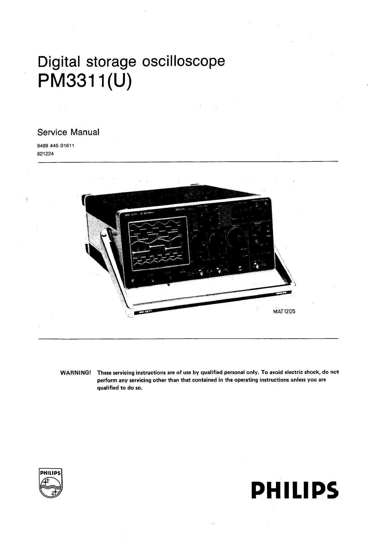
Philips PM3311 PM3311U Digital Storage Oscilloscope Service Manual – 60 MHz Two-Channel
Original price was: $39.95.$24.95Current price is: $24.95.
Complete Philips PM3311(U) 60 MHz digital storage oscilloscope service manual – circuit descriptions, block diagrams, board layouts, checking and adjusting procedures, parts lists and additional diagrams for the two-channel microprocessor-controlled instrument.
Description
Philips PM3311(U) 60 MHz Digital Storage Oscilloscope Service Manual
The Philips PM3311(U) is a portable, two-channel 60 MHz digital storage oscilloscope built around a microprocessor-controlled acquisition system, and this is the complete service documentation package for it. If you own, maintain or repair one of these instruments, this Philips PM3311 service manual gives you the circuit descriptions, block diagrams, board layouts, adjustment procedures and parts information that the operating manual alone cannot provide.
This PDF bundles the operating manual together with the full service manual, modifications, circuit descriptions, dismantling procedures, checking and adjusting routines, corrective maintenance, an introduction to microprocessors, an explanation of the symbols used throughout the schematics, complete parts lists and additional diagrams – everything Philips published for field and bench service of the PM3311(U). Ordering number 9499 445 01611 821224.
File Details
- Manual type: Service manual (with integrated operating manual)
- Brand: Philips
- Model: PM3311(U) Digital Storage Oscilloscope
- Also references: PM3325 IEC Bus Operating Manual
- Language: English
- Page count: Approximately 300 pages
- File format: PDF
- Ordering number: 9499 445 01611 821224
- Operating manual ordering number: 9499 440 23001
Chapters Covered
- Operating Manual PM3311(U) – Tab 1 Operating Manual, Tab 2 Bedienungsanleitung, Tab 3 Notice d’Emploi
- PM3325 I.E.C. Bus Operating Manual
- Service Manual PM3311(U) – Tab 4 Service Manual, Tab 5 Modifications, Tab 6 Circuit Descriptions, Tab 7 Dismantling the Instrument, Tab 8 Checking and Adjusting, Tab 9 Corrective Maintenance, Tab 10 Introduction to Microprocessors, Tab 11 Explanation of Used Symbols, Tab 12 Parts Lists, Additional Diagrams
- Introduction and Characteristics – CRT, vertical deflection, time base, triggering, memory, display modes, plot output, interfaces, XY display, calibration output, power supply, environmental characteristics, dimensions and weight
- Circuit Descriptions – Acquisition system (vertical channels, analog-to-digital converter including P2CCD, trigger and trigger delay circuits, sampling system, time-base system, acquisition control), Display system (memories, dot join and plot, vertical final amplifier, horizontal final amplifier, CRT section, alphanumeric display), Microprocessor and software, Power supply
- Unit Descriptions – A1 Front side, A2 Front, A3 Motherboard, A4 Microprocessor, A5 Spare, A6 RAM, A7 Buffer, A8 Conversion, A9 ACL, A10 CCD logic, A11 P2CCD, A12 Time-base, A13 Delay trigger, A14 IEC, A15 DC power, A16 AC power, A17 Rear side, A18 Delay line, A19 CRT socket, A20 Final amplifier, A21 Amplifier, A22 Trigger, A23 EHT, A34 Driver
- Dismantling the Instrument – warnings, removing the covers, access to parts for checking and adjusting
- Checking and Adjusting – general information, recommended test equipment, preliminary settings, survey of adjusting elements, checking and adjusting procedure (power supply, CRT circuit, pre-adjustment P2CCD circuit, balance adjustments, final amplifier adjustments, vertical channels, time coefficient adjustments, triggering, X-Y mode, range indication, plotter outputs, periodic and random deviations, effect of mains voltage variations), interactions, performance check
- Corrective Maintenance – replacements (knobs, handle, cabinet plates, plug-in units, P2CCD unit, front unit, LEVEL control, trigger mode switch, CRT, delay line, rear plate, DC power unit, mains filter, EHT unit, vertical amplifier, trigger unit), soldering techniques, handling MOS devices, special tools, recalibration after repair, instrument repackaging, troubleshooting (power-up routine, trouble shooting aids, service faultfinding software routines, trouble shooting hints, overall view of provisions and service methods, mains voltage setting)
- Introduction to Microprocessors
- Explanation of Used Symbols
- Parts Lists – mechanical parts and electrical parts
- Additional Diagrams
Technical Highlights of the PM3311(U)
The oscilloscope uses a D14-292 GH/39 cathode ray tube with a 10 kV accelerating voltage and an 8 x 10 cm screen with illuminated graticule lines. Vertical deflection spans 10 mV/div to 50 V/div in twelve calibrated 1-2-5 positions, with a frequency range of DC to 60 MHz (AC coupled 10 Hz to 60 MHz) and a rise time under 6 ns. Input impedance is 1 MOhm // 25 pF with a maximum safe input of 400 V DC plus AC peak. Time coefficients run from 5 ns/div to 60 min/div, with a maximum sample rate of 125 MHz and 25 samples per division resolution.
Four memories (one accumulator plus three store registers) hold signal data, and the instrument supports Single, Recurrent, Roll and Multiple operating modes. An optional IEC bus interface can be added via the PM3325 plug-in board, and plotter outputs are provided for chart recording. Supply voltage is switchable between 100-120 V and 220-240 V ranges, both at 10 percent tolerance. Memory back-up is provided by two 1.5 V penlight batteries. The instrument weighs approximately 12 kg and measures 460 mm long, 316 mm wide and 154 mm high excluding handle and controls.
From Circuit Descriptions to Corrective Maintenance
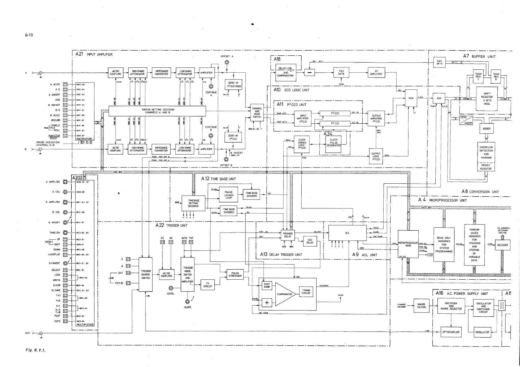
The circuit descriptions chapter is the technical heart of this Philips PM3311(U) service manual. It explains the acquisition system in full – the two identical vertical channels A and B, the analog-to-digital conversion chain with the Profiled Peristaltic Charge Coupled Device (P2CCD), the trigger and trigger delay circuits, the sampling system, the time-base system and the acquisition control logic. Each of the four system modes (Direct, Roll, Sampling and P2CCD) is described with its own timing diagram so you can follow exactly what the microprocessor expects from the hardware in each mode.
The display system coverage walks through the ACCU and STO1-3 memories, the dot-join and plot circuits, the vertical and horizontal final amplifiers, the CRT section and the alphanumeric display. The microprocessor chapter explains the 8085-based control system, its address and data buses, the memory map, ROM and RAM usage, the trap and watchdog circuits and the blanking arrangement for the CRT.
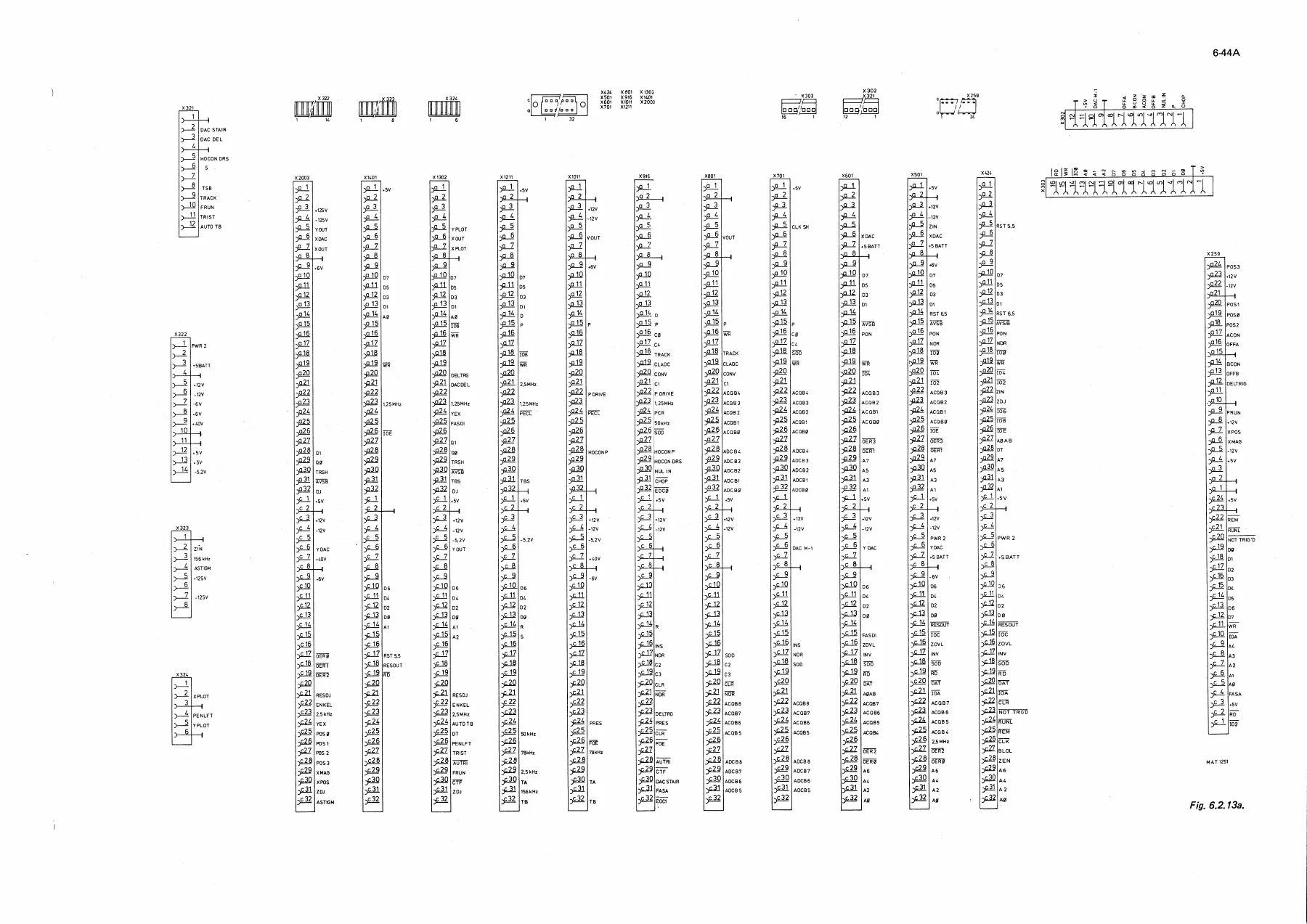
The unit descriptions section is where you get practical board-level detail. Each plug-in unit is described in turn – front side A1, front A2, motherboard A3, microprocessor A4, spare A5, RAM A6, buffer A7, conversion A8, ACL A9, CCD logic A10, P2CCD A11, time-base A12, delay trigger A13, IEC A14, DC power A15, AC power A16, rear side A17, delay line A18, CRT socket A19, final amplifier A20, amplifier A21, trigger A22, EHT A23 and driver A34. For every unit you get a functional description of the circuit blocks, the incoming and outgoing signals with their generated and used units, test point locations and connector pinouts.
The dismantling chapter covers the mechanical side – removing the upper and lower cabinet plates after slackening the four quick-release fasteners, removing the rear panel to access the AC and DC power units, and the specific procedures for replacing single and double knobs, the carrying handle, the cabinet plates, the screen bezel, the plug-in units, the P2CCD unit, the front unit, the LEVEL control, the trigger mode switch, the CRT, the delay line unit, the rear plate with AC power unit, the DC power unit, the mains filter, the EHT unit, the vertical amplifier unit and the trigger unit.
Checking, Adjusting and Troubleshooting
The checking and adjusting chapter opens with recommended test equipment (constant amplitude sine-wave generator, time mark generator, square-wave calibration generator, low-frequency generator, cables, trimming probe, variable mains transformer, monolith meter, oscilloscope and digital multimeter) and moves into the full adjustment sequence. Because the control functions are interdependent, the procedure is presented in the order Philips recommends, with cross-references to any circuit that affects a particular adjustment.
Individual adjustment groups include power supply (current consumption, +12 V and +5 V rails, oscillator frequency), cathode-ray-tube circuit (cathode voltage, intensity, focus and astigmatism, trace rotation), pre-adjustment P2CCD circuit (low-frequency, 0.5 microsecond/div and 0.2 microsecond/div P2CCD adjustments), balance adjustments (vertical amplifier, trigger point symmetry, trigger balances AC-DC for external, A, B and LINE, trigger amplifier balance), final amplifier adjustments (vertical trace height, display positions, invert registers, horizontal trace length, dot join, calibration voltage), vertical channels (sensitivity, input attenuators, square-wave response, bandwidth, OFFSET control range, common mode rejection), time coefficient adjustments (recurrent mode, roll mode, effective delay, single shot, multiple, VCO), triggering (sensitivity, slope and level, AUTO, EXT, EXT divided by 10, mains frequency triggering, TV triggering, trigger delay adjustment), X-Y mode, range indication and plotter outputs.
The corrective maintenance chapter gives you the practical repair workflow – replacement procedures for the major assemblies, soldering techniques, handling of MOS devices, the special tools needed, recalibration requirements after repair, instrument repackaging and a dedicated troubleshooting section. The troubleshooting material includes the power-up routine, trouble shooting aids, service faultfinding software routines, trouble shooting hints, an overall view of provisions and service methods, and the mains voltage setting procedure. If the PM3311 comes up dead or the display misbehaves, this is where you start.
Why This Manual Matters for PM3311 Owners
Digital storage oscilloscopes of this era combine analog acquisition, charge-coupled device storage, microprocessor control and a high-voltage CRT supply in one chassis – there is nowhere to hide from a fault, and guesswork is expensive. The Philips PM3311 service manual removes that guesswork by giving you the complete signal path from input socket through the attenuators, the P2CCD, the ADC and correction circuits, the RAM and DAC chain, the dot-join circuitry and the final amplifiers to the deflection plates. Every test point, every connector and every adjustment is documented, and the block diagrams let you trace a signal fault back to a specific board before you start pulling plug-in units.
The parts lists chapter gives you the mechanical and electrical part numbers, and the additional diagrams section adds the schematics and supplementary drawings needed when a component-level repair is the only option. Between the circuit descriptions, unit descriptions, checking and adjusting procedures and corrective maintenance chapter, this is the reference a workshop needs to keep a PM3311(U) on the bench and in calibration rather than retired to a shelf.
IMAGES PREVIEW
Instant PDF Delivery
This Philips PM3311 PM3311U Digital Storage Oscilloscope Service Manual is delivered as an instant PDF download – no shipping, no waiting, no physical media. Open it on any laptop, tablet or phone in the workshop, zoom into the block diagrams and board layouts, print the pages you need for the bench, and keep the file on hand for every future repair. Whether you are balancing the trigger amplifier, chasing a dot-join fault, adjusting the P2CCD zero level, replacing the EHT unit or simply working through the periodic performance check, the procedures and specifications in this manual are the ones that keep the instrument accurate. Add it to your library today and repair with confidence.
Reviews
There are no reviews yet.