★ TRUSTED BY 321,897+ PROFESSIONALS WORLDWIDE
🏒
Trusted Business
Verified & Licensed
πŸ›‘οΈ
Virus Free Files
100% Safe Downloads
πŸ”’
Secure Payment
SSL Protected
⚑
Instant Delivery
Available Immediately
Sale!

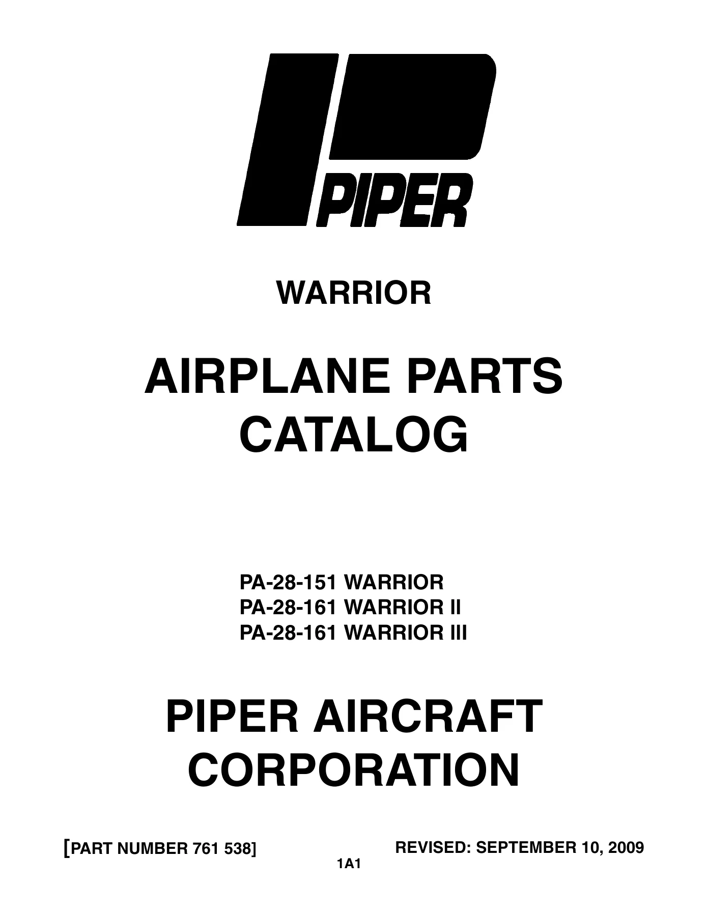
Piper PA-28-151/161 Warrior Warrior II Warrior III Airplane Parts Catalog 761 538

Original price was: $39.95.Current price is: $24.95.

Complete illustrated Piper parts catalog (Doc 761 538) covering the PA-28-151 Warrior, PA-28-161 Warrior II, and PA-28-161 Warrior III. Every figure, index number, Piper part number, nomenclature, quantity, and serial number effectivity for the full airplane – 422 pages, instant PDF download.

⚑
Instant PDF Download
Available immediately
πŸ’Ύ
Save to Your Device
Download & keep forever
πŸ›‘οΈ
Antivirus Scanned
100% virus-free
🌍
Trusted Worldwide
175,000+ customers

Description

File Details

  • Manual Type: Illustrated Airplane Parts Catalog
  • Brand: Piper Aircraft Corporation
  • Models Covered: PA-28-151 Warrior, PA-28-161 Warrior II, PA-28-161 Warrior III
  • Document Number: 761 538
  • Original Issue: June 11, 1979
  • Latest Revision: September 10, 2009 (PR090910)
  • Publisher: Piper Aircraft Corporation, Technical Publications, Vero Beach, Florida
  • Language: English
  • Page Count: 422 pages
  • File Format: PDF

What the Piper Warrior Parts Catalog 761 538 Delivers

This is the complete illustrated replacement parts catalog for the Piper PA-28-151 Warrior, PA-28-161 Warrior II, and PA-28-161 Warrior III. Every figure, index number, Piper part number, nomenclature, quantity required, and serial number effectivity across the entire airplane is indexed here in one document. If a component exists on a Warrior airframe and it can be ordered, this catalog shows the number to order it by. The catalog was originally issued June 11, 1979 and carries revisions through September 10, 2009, so late-production Warrior III serials are included alongside the earliest 1974 PA-28-151s.

The document is split into thirteen major sections covering the complete airplane, followed by a Miscellaneous Group for placards, optional equipment kits, repair kits, special tools, and consumable hardware. Each section is subdivided into figures – exploded illustrations of each assembly – paired with a parts listing that ties the figure index numbers to the actual part numbers.

Sections Covered in This Piper PA-28-151 / PA-28-161 Parts Manual

  • Section I – Wing Group: Wing Installation, Wing Leading Edge Assembly, Wing Trailing Edge Assembly, Aileron Assembly (early and later serials), Flap Assembly
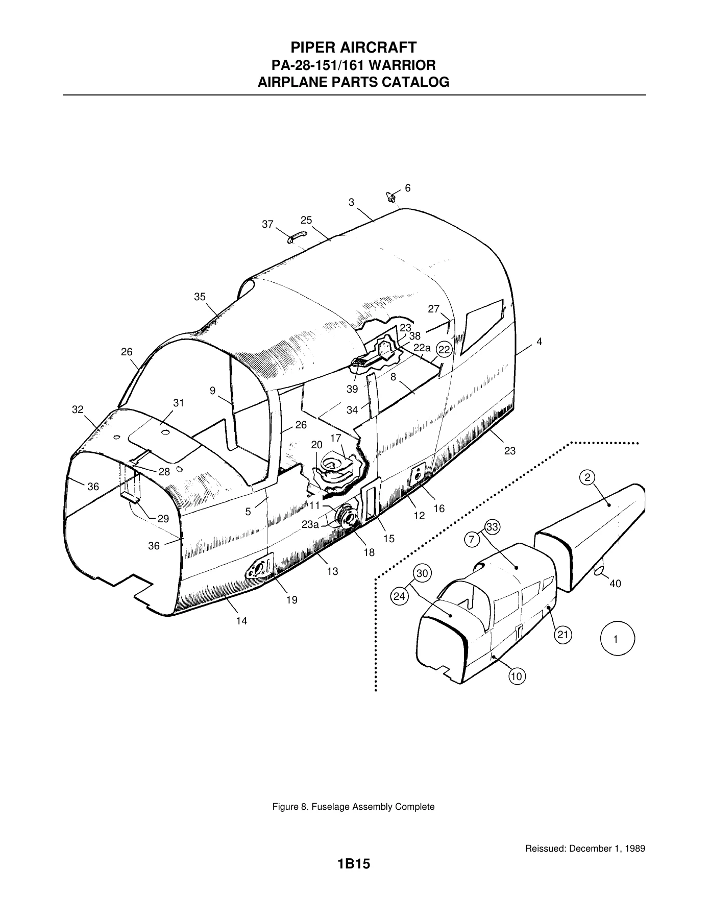
  • Section II – Fuselage Group: Fuselage Assembly Complete, Upper Forward Cockpit Assembly, Upper Center Cockpit Assembly, Lower Forward Cockpit Assembly, Lower Aft Cockpit Assembly, Fuselage Aft Section, Baggage Door Assembly, Cabin Door Assembly, Fuselage Enclosure Installation
  • Section III – Tail Surfaces Group: Tail Surfaces Installation, Stabilator Assembly, Fin Assembly, Rudder Assembly
  • Section IV – Landing Gear Group: Nose Gear Installation, Nose Gear Strut Assembly, Nose Wheel Assembly (Cleveland and McCauley), Main Gear Installation, Main Wheel Assembly, Brake Assembly, Main and Nose Wheel Fairing Installation, Main Landing Gear Strut Fairing Installation, Hand Brake Installation, Toe Brake Installation, Toe Brake Master Cylinder Assembly
  • Section V – Cabin Equipment Group: Cockpit Finishing Installation, Window Curtains Installation, Carpet Installation, Seats Installation, Vertically Adjustable Front Seat Assembly
  • Section VI – Instruments Group: Instrument Panel Installation, Vacuum System Installation, Auxiliary Vacuum System Installation, Pitot Static System Installation
  • Section VII – Power Plant Group: Power Plant Installation, Engine Exhaust System Installation, Engine Baffle Installation, Oil Cooler Installation, Engine Cowl Installation, Engine Controls Installation
  • Section VIII – Fuel System Group: Forward Fuel System Installation, Aft Fuel System Installation, Fuel Tank Assembly
  • Section IX – Control System Group: Control System Installation, Flap Control Installation, Stabilator Trim Installation, Rudder Trim Mechanism Installation, Control Wheel Installation, Rudder Pedal Installation
  • Section X – Environmental Group: Cabin Heat and Defroster Installation, Cabin Overhead Air Vent Installation, Air Conditioning Compressor, Refrigerant Lines and Alternator Installation, Air Conditioning Duct and Evaporator Installation, Air Conditioning Condenser Installation
  • Section XI – Electrical System Group: Electrical System Installation, Instrument Panel Electrical Installation, Air Conditioning Electrical Installation, Battery Box Installation, External Power Supply Installation, Auxiliary Power Receptacle Installation, Alternator Assembly (Prestolite), Alternator Installation (Chrysler), Strobe Light Installation
  • Section XII – Electronics Group: Electric Trim Installation, AutoFlite II Installation, AutoControl III and IIIB Installation, Century 21 AutoPilot Installation, King KAP 100/150 AutoPilot Installation, Piper Automatic Locator (ELT) installations, Radar Altimeter Installation, Encoder Installation, Piper PM-1 Marker Beacon Installation, Radio, Antenna System and Static Wicks Installation, Audio Selector Assembly, Avionics Cooling Installation
  • Section XIII – Miscellaneous Group: Placards and Exterior Stencils, Optional Equipment Kits and Repair Kits, Miscellaneous Hardware and Consumables

Between the illustrated figures and the parts listings, this catalog gives a technician or restorer the full bill of materials for any Warrior assembly – down to the attaching hardware in many cases. The introductory notes explain how to read the figure and index numbers, how the asterisk indention system identifies sub-assemblies versus individual parts, how the CODE column flags special-use parts, and how the SERIAL NUMBERS AFFECTED column isolates the exact part for a specific airplane. Piper has also documented the parts affected by each applicable Service Bulletin and Service Letter, so a purchaser can match replacements to the current airworthiness status of the airframe.

Serial Number Coverage

Serial number ranges run from the first 1974 PA-28-151 Warrior (28-7415001) through the final PA-28-161 Warrior III (2816119). The catalog breaks out the serial-specific parts for each model year, including the four-set numbering system used through the 1980s and the three-set system adopted in late 1986. Serial numbers affected are printed against every applicable part so the correct configuration is identified on the first try.

Engines and Engine Variants Referenced

  • Lycoming 0-320-E3D (PA-28-151 Warrior, early serials)
  • Lycoming 0-320-D3G with Slick magnetos (PA-28-161 Warrior)
  • Lycoming 0-320-D3G with Bendix magnetos (PA-28-161 Warrior, later serials)

Why the Piper Warrior Parts Catalog 761 538 Belongs in the Hangar

Airframe repairs, annual inspections, and restorations all stall on the same problem – identifying and ordering the right part. Generic parts references and guesswork produce the wrong item, an extra week of downtime, and a second freight bill. This parts catalog removes that friction. Every illustrated figure is cross-referenced to a part number that Piper still recognises, and the serial number effectivity flags keep buyers from installing a part that was designed for a different production block.

For a shop running PA-28 series aircraft, this catalog is the reference that sits on the bench while the phone call to the distributor is being placed. For the private owner managing a rebuild, it is the difference between one purchase order and three.

Complete PDF Bookmark Tree

Complete Bookmarks

The complete bookmarks in the β€œPiper PA-28-151/161 Warrior Warrior II Warrior III Airplane Parts Catalog 761 538” are as follows:

761-538 – WARRIOR PARTS CATALOG – PA-28-151 WARRIOR/161-WARRIOR II/IIIp. 1
REVISION STATUSp. 3
INTRODUCTIONp. 4
GRID NUMBERINGp. 5
HOW TO IDENTIFY A PART IF YOU KNOW WHAT IT LOOKS LIKE AND KNOW WHERE IT IS LOCATEDp. 5
HOW TO ORDER PARTSp. 5
GENERAL INFORMATIONp. 5
MODEL SERIAL NUMBER INFORMATIONp. 6
SERIAL NUMBER EXPLANATIONp. 6
STANDARD PAINT CHARTp. 7
TABLE OF CONTENTSp. 9
SERVICE BULLETINS / SERVICE LETTERS / SERVICE SPARES LETTERS INCORPORATEDp. 12
FIGURE 1. VIEW OF COMPLETE AIRPLANEp. 13
SECTION I – WING GROUPp. 15
FIGURE 2. WING INSTALLATIONp. 15
FIGURE 3. WING LEADING EDGE ASSEMBLYp. 20
FIGURE 4. WING TRAILING EDGE ASSEMBLYp. 24
FIGURE 5. AILERON ASSEMBLY (28-7415001 THRU 28-7515459)p. 29
FIGURE 6. AILERON ASSEMBLY (28-7615001 AND UP, AND 28-7716001 AND UP)p. 33
FIGURE 7. FLAP ASSEMBLYp. 36
SECTION II – FUSELAGE GROUPp. 39
FIGURE 8. FUSELAGE ASSEMBLY COMPLETEp. 39
FIGURE 9. FUSELAGE UPPER FORWARD COCKPIT ASSEMBLYp. 43
FIGURE 10. FUSELAGE UPPER CENTER COCKPIT ASSEMBLYp. 47
FIGURE 11. FUSELAGE LOWER FORWARD COCKPIT ASSEMBLYp. 52
FIGURE 12. FUSELAGE LOWER AFT COCKPIT ASSEMBLYp. 56
FIGURE 13. FUSELAGE AFT SECTIONp. 59
FIGURE 14. FUSELAGE BAGGAGE DOOR ASSEMBLYp. 63
FIGURE 15. FUSELAGE CABIN DOOR ASSEMBLY (28-7415001 THRU 28-7615001)p. 66
FIGURE 16. FUSELAGE CABIN DOOR ASSEMBLY (28-7615002 AND UP, AND 28-7716001 AND UP)p. 70
FIGURE 17. FUSELAGE ENCLOSURE INSTALLATIONp. 75
SECTION III – TAIL SURFACES GROUPp. 81
FIGURE 18. TAIL SURFACES INSTALLATIONp. 81
FIGURE 19. STABILATOR ASSEMBLYp. 85
FIGURE 20. FIN ASSEMBLYp. 88
FIGURE 21. RUDDER ASSEMBLYp. 91
SECTION IV – LANDING GEAR GROUPp. 95
FIGURE 22. NOSE GEAR INSTALLATIONp. 95
FIGURE 23. NOSE GEAR STRUT ASSEMBLYp. 99
FIGURE 24. NOSE WHEEL ASSEMBLY (CLEVELAND)p. 103
FIGURE 25. NOSE WHEEL ASSEMBLY (MCCAULEY)p. 106
FIGURE 26. MAIN GEAR INSTALLATIONp. 109
FIGURE 27. MAIN WHEEL ASSEMBLYp. 113
FIGURE 28. BRAKE ASSEMBLYp. 116
FIGURE 29. MAIN AND NOSE WHEEL FAIRING INSTALLATION (28-7415001 AND UP, AND 28-7716001 THRU 28-7716323)p. 119
FIGURE 30. MAIN AND NOSE WHEEL FAIRING INSTALLATION (28-7816001 AND UP)p. 122
FIGURE 31. MAIN LANDING GEAR STRUT FAIRING INSTALLATIONp. 126
FIGURE 32. HAND BRAKE INSTALLATIONp. 129
FIGURE 33. TOE BRAKE INSTALLATIONp. 132
FIGURE 34. TOE BRAKE MASTER CYLINDER ASSEMBLYp. 135
SECTION V – CABIN EQUIPMENT GROUPp. 139
FIGURE 35. COCKPIT FINISHING INSTALLATIONp. 139
FIGURE 36. WINDOW CURTAINS INSTALLATION (S/N 28-8016001 AND UP)p. 147
FIGURE 37. CARPET INSTALLATIONp. 150
FIGURE 38. SEATS INSTALLATIONp. 157
FIGURE 39. VERTICALLY ADJUSTABLE FRONT SEAT ASSEMBLYp. 163
SECTION VI – INSTRUMENT GROUPp. 169
FIGURE 40. INSTRUMENT PANEL INSTALLATION (S/N 28-7415001 AND UP, AND 28-7716001 THRU 2816109)p. 169
FIGURE 40A. INSTRUMENT PANEL INSTALLATION (S/N 2816110 AND UP)p. 175
FIGURE 41. VACUUM SYSTEM INSTALLATION (S/N 28-7415001 AND UP, AND 28-7716001 THRU 2816109)p. 178
FIGURE 41A. VACUUM SYSTEM INSTALLATION (S/N 2816110 AND UP)p. 181
FIGURE 41B. AUXILIARY VACUUM SYSTEM INSTALLATIONp. 184
FIGURE 42. PITOT STATIC SYSTEM INSTALLATIONp. 188
SECTION VII – POWER PLANT GROUPp. 193
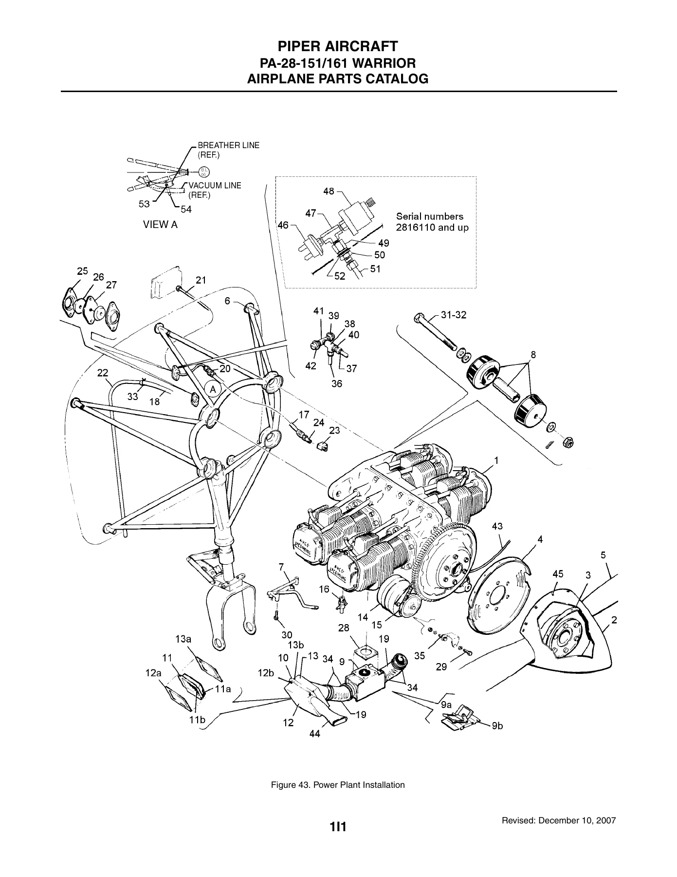
FIGURE 43. POWER PLANT INSTALLATIONp. 193
FIGURE 44. ENGINE EXHAUST SYSTEM INSTALLATIONp. 197
FIGURE 45. ENGINE BAFFLE INSTALLATIONp. 200
FIGURE 46. OIL COOLER INSTALLATIONp. 203
FIGURE 47. ENGINE COWL INSTALLATIONp. 206
FIGURE 48. ENGINE CONTROLS INSTALLATIONp. 209
SECTION VIII – FUEL SYSTEM GROUPp. 213
FIGURE 49. FORWARD FUEL SYSTEM INSTALLATIONp. 213
FIGURE 50. AFT FUEL SYSTEM INSTALLATION (S/N 28-7415001 THRU 28-7515459)p. 217
FIGURE 51. AFT FUEL SYSTEM INSTALLATION (S/N 28-7615001 AND UP AND 28-7716001 AND UP)p. 220
FIGURE 52. FUEL TANK ASSEMBLYp. 223
SECTION IX – CONTROL SYSTEM GROUPp. 227
FIGURE 53. CONTROL SYSTEM INSTALLATIONp. 227
FIGURE 54. FLAP CONTROL INSTALLATIONp. 231
FIGURE 55. STABILATOR TRIM INSTALLATIONp. 235
FIGURE 56. RUDDER TRIM MECHANISM INSTALLATIONp. 239
FIGURE 57. CONTROL WHEEL INSTALLATIONp. 242
FIGURE 58. RUDDER PEDAL INSTALLATIONp. 246
SECTION X – ENVIRONMENTAL GROUPp. 249
FIGURE 59. CABIN HEAT AND DEFROSTER INSTALLATIONp. 249
FIGURE 60. CABIN OVERHEAD AIR VENT INSTALLATIONp. 253
FIGURE 61. AIR CONDITIONING COMPRESSOR, REFRIGERANT LINES AND ALTERNATOR INSTALLATION (28-7816001 AND UP)p. 257
FIGURE 62. AIR CONDITIONING DUCT AND EVAPORATOR INSTALLATION (S/N 28-7816001 AND UP)p. 261
FIGURE 63. AIR CONDITIONING CONDENSER INSTALLATION (S/N 28-7816001 AND UP)p. 264
SECTION XI – ELECTRICAL SYSTEM GROUPp. 283
FIGURE 64. ELECTRICAL SYSTEM INSTALLATIONp. 283
FIGURE 65. INSTRUMENT PANEL ELECTRICAL INSTALLATION (S/N 28-7415001 AND UP, 28-7716001 THRU 2816109)p. 288
FIGURE 65A. INSTRUMENT PANEL ELECTRICAL INSTALLATION (S/N 2816110 AND UP)p. 292
FIGURE 66. AIR CONDITIONING ELECTRICAL INSTALLATION (S/N 28-7816001 AND UP)p. 296
FIGURE 67. BATTERY BOX INSTALLATIONp. 299
FIGURE 68. EXTERNAL POWER SUPPLY INSTALLATION (S/N 28-7415001 AND UP AND 28-7716001 THRU 28-8216236)p. 304
FIGURE 68A. EXTERNAL POWER SUPPLY INSTALLATION (S/N 28-8316001 THRU 2816109)p. 307
FIGURE 68B. AUXILIARY POWER RECEPTACLE INSTALLATION (S/N 2816110 AND UP)p. 310
FIGURE 69. ALTERNATOR ASSEMBLY (PRESTOLITE)p. 313
FIGURE 70. ALTERNATOR INSTALLATION (CHRYSLER)p. 316
FIGURE 71. STROBE LIGHT INSTALLATIONp. 320
SECTION XII – ELECTRONICS GROUPp. 327
FIGURE 72. ELECTRIC TRIM INSTALLATIONp. 327
FIGURE 73. AUTOFLITE II INSTALLATIONp. 330
FIGURE 74. AUTOCONTROL III AND IIIB INSTALLATION (28-7415001 AND UP AND 28-7716001 THRU 28-8216236)p. 333
FIGURE 75. CENTURY 21 AUTOPILOT INSTALLATION (28-8116019 AND UP)p. 336
FIGURE 75A. KING KAP 100/150 AUTOPILOT INSTALLATION (28-8316001 AND UP)p. 339
FIGURE 76. PIPER AUTOMATIC LOCATOR (ELT) INSTALLATION (GARRET MFG. LTD.)p. 342
FIGURE 77. PIPER AUTOMATIC LOCATOR (ELT) INSTALLATION (COMMUNICATIONS COMPONENTS CORP.)p. 345
FIGURE 78. PIPER AUTOMATIC LOCATOR (ELT 10) INSTALLATION (NARCO AVIONICS)p. 348
FIGURE 78A. PIPER AUTOMATIC LOCATOR (ELT 910) INSTALLATION (NARCO AVIONICS)p. 351
FIGURE 78B. EMERGENCY LOCATOR INSTALLATION (ELT-110-4) SERIAL NUMBERS 2816094 AND UPp. 354
FIGURE 79. RADAR ALTIMETER INSTALLATIONp. 356
FIGURE 80. ENCODER INSTALLATION (NARCO-AR 500 AND UNITED-5125-P3)p. 359
FIGURE 81. PIPER PM-1 MARKER BEACON INSTALLATION (28-7415001 THRU 28-7415713)p. 362
FIGURE 82. RADIO, ANTENNA SYSTEM AND STATIC WICKS INSTALLATIONp. 365
FIGURE 83. AUDIO SELECTOR ASSEMBLYp. 369
FIGURE 84. AVIONICS COOLING INSTALLATIONp. 372
AVIONICS INSTALLATION DRAWINGSp. 375
SECTION XIII – MISCELLANEOUS GROUPp. 379
FIGURE 85. PLACARDS AND EXTERIOR STENCILSp. 379
OPTIONAL EQUIPMENT KITS AND REPAIR KITSp. 385
MISCELLANEOUS HARDWARE AND CONSUMABLESp. 389
NUMERICAL INDEXp. 391


IMAGES PREVIEW

Piper PA-28-151/161 Warrior Warrior II Warrior III Airplane Parts Catalog 761 538 β€” PDF page 1 preview
Piper PA-28-151/161 Warrior Warrior II Warrior III Airplane Parts Catalog 761 538 β€” PDF page 39 preview
Piper PA-28-151/161 Warrior Warrior II Warrior III Airplane Parts Catalog 761 538 β€” PDF page 193 preview

Instant PDF Delivery

The Piper PA-28-151/161 Warrior Warrior II Warrior III Airplane Parts Catalog 761 538 is delivered as a complete PDF that opens on any device – laptop, tablet, or phone – and can be printed page by page for a shop binder. No shipping, no waiting on a physical book, no risk of a bound copy going missing in the hangar. Order the download, open the file, find the figure, and order the part the same afternoon.
Reviews

There are no reviews yet.

Be the first to review “Piper PA-28-151/161 Warrior Warrior II Warrior III Airplane Parts Catalog 761 538”

What Our Customers Say

β˜…β˜…β˜…β˜…β˜… Live reviews from customers
Loading customer reviews...
0
    0
    Your Cart
    Your cart is emptyReturn to Shop
    πŸ›’
    Recently Purchased
    πŸ•’ verified order