
Piper PA-32RT-300 & PA-32RT-300T Lance II Illustrated Parts Catalog 761-640
Original price was: $34.95.$19.95Current price is: $19.95.
Complete illustrated Piper parts catalog 761-640 for the PA-32RT-300 Lance II and PA-32RT-300T Turbo Lance II – every figure, part number, index and serial-number application across all fourteen sections of the aircraft.
Description
Piper PA-32RT-300 & PA-32RT-300T Lance II Illustrated Parts Catalog 761-640
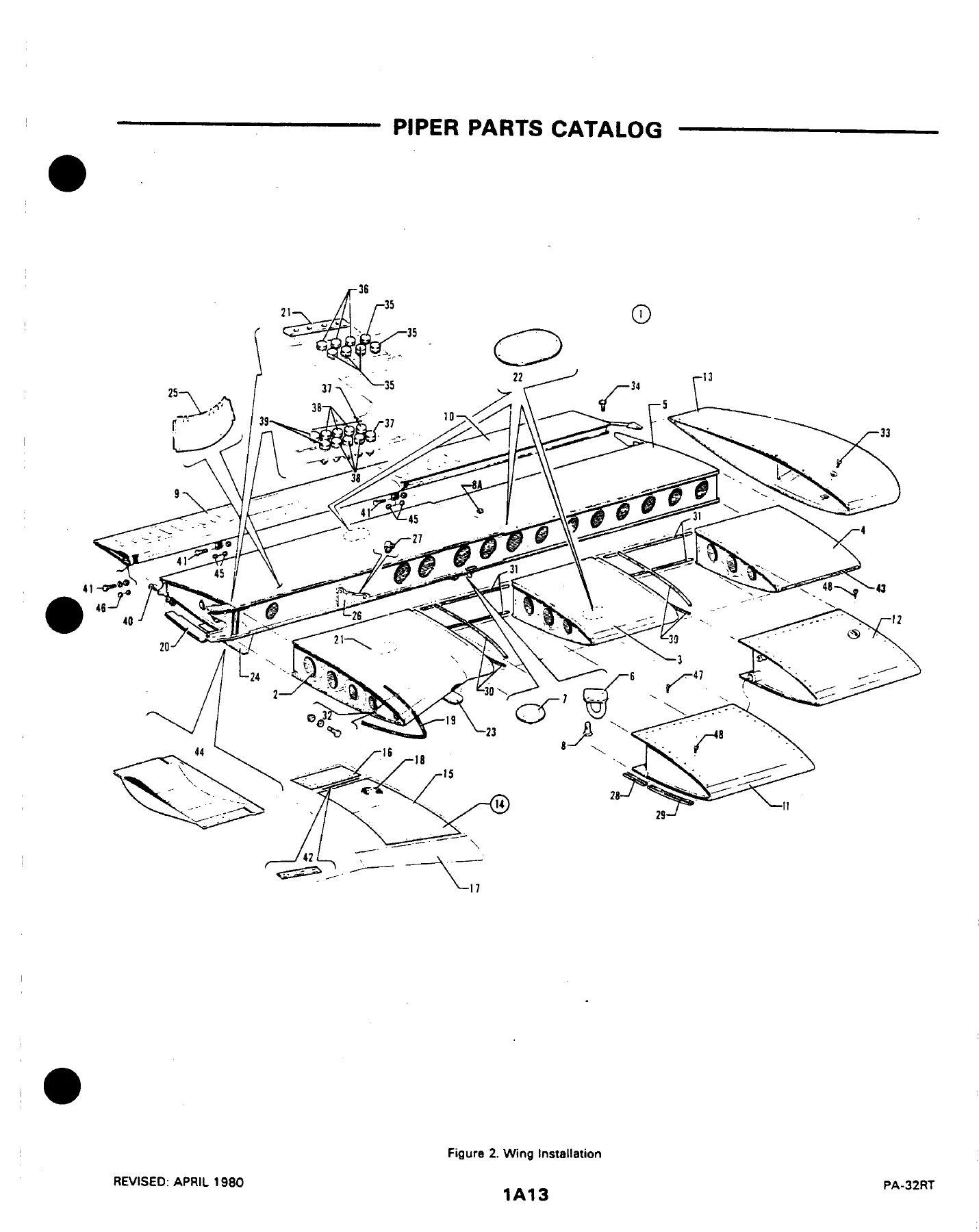
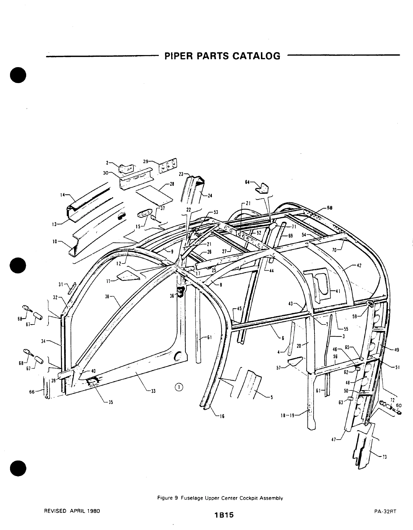
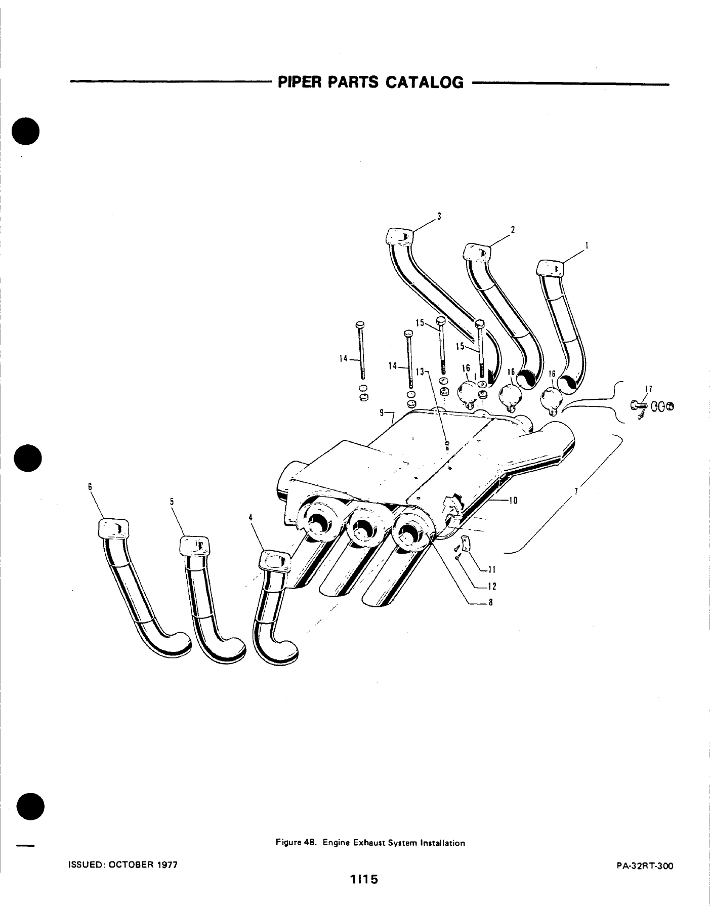
This is the Piper Parts Catalog covering the PA-32RT-300 Lance II and the turbocharged PA-32RT-300T, published under document number 761-640. It was originally issued on October 28, 1977 and consolidated through the January 1983 revision, giving you the accumulated parts breakdown for both normally aspirated and turbocharged Lance II airframes. Every replacement part in the catalog carries a Piper part number, a figure-and-index reference tying it back to its illustration, and where applicable a serial-number range showing which aircraft the part fits.
File Details
- Manual type: Illustrated Parts Catalog (Aerofiche format)
- Brand: Piper Aircraft Corporation
- Models covered: PA-32RT-300 Lance II, PA-32RT-300T Turbo Lance II
- Document number: 761-640
- Original issue date: October 28, 1977
- Revisions incorporated: September 1978, May 1979, April 1980, April 1981, January 1983
- Aerofiche set: Two cards (card 1 of 2 and card 2 of 2)
- Language: English
- Format: PDF
Chapters Covered
The catalog is organised into fourteen major sections. Each section is further divided into illustrated sub-groups, and every sub-group carries its own parts listing.
- Section I – Wing Group: Wing Installation; Leading Edge Assembly; Trailing Edge Assembly; Aileron Assembly; Flap Assembly
- Section II – Fuselage Group: Fuselage Assembly Complete; Upper Forward, Center and Aft Cockpit Assemblies; Lower Forward and Aft Cockpit Assemblies; Aft Section; Forward Cabin Door; Aft Cabin Door; Forward Baggage Door; Aft Cargo Door; Enclosure Installation
- Section III – Tail Surfaces Group: Tail Surfaces Installation; Stabilator Assembly; Fin Assembly; Rudder Assembly
- Section IV – Landing Gear Group: Nose Gear Installation and Assembly; Cleveland and McCauley Nose Wheels; Main Gear Installation and Assembly; Main Wheel Assembly; Brake Assembly; Landing Gear Doors (PA-32RT-300 and PA-32RT-300T); Hand Brake Installation; Toe Brake Installation; Toe Brake Master Cylinder Assembly
- Section V – Cabin Equipment Group: Cockpit Finishing Installation; Window Curtain Installation; Carpet Installation; Headliner and Forward Air Duct Installation; Seats Installation; Vertically Adjustable Front Seat Assembly; 7th Seat Installation; Aft Facing Center Seat Assembly; Club Seating Installation
- Section VI – Instruments Group: Instrument Panel Installation; Vacuum System Installation; Pitot Static System Installation
- Section VII – Power Plant Group: Power Plant Installation (PA-32RT-300 and PA-32RT-300T); Engine Instrument Lines; Engine Exhaust System; Engine Baffle Installation; Engine Cowl Assembly; Propeller Assembly; Engine Controls Installation
- Section VIII – Fuel System Group: Forward Fuel System Installation; Aft Fuel System Installation; Fuel Tank Assemblies
- Section IX – Control System Group: Control System Installation; Flap Control Installation; Stabilator Trim Installation; Rudder Trim Mechanism Installation; Control Wheel Installation; Rudder Pedal Installation
- Section X – Hydraulic System Group: Hydraulic System Installation
- Section XI – Environmental Group: Cabin Heat and Defroster System; Aft Fresh Air Duct Installation; Air Conditioning Compressor, Refrigerant Lines and Alternator Installation; Air Conditioning Duct and Evaporator Installation; Air Conditioning Condenser Installation
- Section XII – Electrical System Group: Electrical System Installation; Instrument Panel Electrical Installation; Air Conditioning Electrical Installation; Battery Box Installation; External Power Supply Installation; Standard Alternator Assembly (Chrysler); Air Conditioning Alternator Assembly (Prestolite)
- Section XIII – Electronics Group: Electric Trim Installation; AutoFlite II Installation; AutoControl III B Installation; AltiMatic III C Installation; King KFC-200 AutoPilot Installation; Piper Automatic Locator (ELT) Installations; Radar Altimeter Installation; Encoder Installation; Radio, Antenna System and Static Wicks Installation; Audio Selector Assembly; Radar System Installation; Radio Installation Drawings
- Section XIV – Miscellaneous Group: Placards and Exterior Stencils; Optional Equipment Kits and Repair Kits
- Standard Paint Chart: Acrylic Lacquer and Polyurethane Enamel exterior finish references
What separates this catalog from a generic service book is the way every part is anchored. The “Figure and Index Number” column ties each listing back to a numbered callout on the matching exploded illustration, so you can look at a drawing of the stabilator, find callout 23, and read straight across to the part number, description and quantity required. Indented listings show assembly hierarchy – order the parent assembly and you receive the components listed beneath it, or order the sub-component on its own. The “No. Req.” column tells you whether the quantity is per figure or per assembly, and the “AR” symbol flags parts used as required. The “Serial Numbers Affected” column is particularly valuable on a twin-variant catalog like this one, because so many Lance II parts were changed between the 1978 and 1979 production runs, or between the normally aspirated and turbocharged airframes. Codes throughout the listings direct parts with a “W” suffix to the Lock Haven spares department and everything else to Vero Beach, so you know which supply channel a part belongs to before you place an order.
The document also carries Piper’s own ordering and identification guidance – how to trace a part from its location on the aircraft, how to read the indent structure in the nomenclature column, and what information to supply when ordering. A complete table of contents at the start of each card lets you move directly to the figure you need instead of scanning hundreds of pages.
What This Lance II Parts Catalog Lets You Do
Whether you are maintaining a 1978 PA-32RT-300, a 1979 Turbo Lance II, or any aircraft in the covered serial ranges, this catalog gives you the identification layer that repair work depends on. You can trace a worn or damaged component from its position on the airframe diagram to its correct Piper part number, confirm whether that number applies to your specific serial number, and see exactly how many are required and what it attaches to.
That matters most when parts have been superseded. The catalog’s revision history runs through January 1983, and the code explanations scattered through the figures call out the differences directly – for example, stabilator trim barrel changes by serial number break, or landing gear door hardware that differs between the PA-32RT-300 and the PA-32RT-300T. Ordering the wrong variant of a small bracket or a trim cable is an expensive mistake, and the serial-number column is what prevents it.
Because the coverage spans wings, fuselage structure, tail surfaces, landing gear, brakes, cabin interior, instruments, power plant, exhaust, baffles, cowl, propeller, fuel system, flight controls, hydraulics, environmental systems, electrical system and the full electronics/avionics group, one document handles nearly every identification question that comes up on these aircraft. Airframe shops, avionics installers, interior refurbishers and owner-maintainers all work from the same reference.
IMAGES PREVIEW
Delivered as an instant PDF download – no shipping, no waiting, and no physical binder to keep track of. Open it on a workshop laptop, a tablet at the aircraft, or a phone in the hangar. Print just the figures you need for the job in front of you, whether that is a single page or the whole wing group.
Reviews
There are no reviews yet.