
Piper PA-46-500TP Malibu Meridian Airplane Parts Catalog – Part Number 767-004
Original price was: $39.95.$24.95Current price is: $24.95.
Comprehensive factory illustrated parts catalog for the Piper PA-46-500TP Malibu Meridian turboprop aircraft (Serial Numbers 4697001 and up, without Garmin G1000). Features full airframe exploded diagrams, structural assemblies, systems breakdowns, part numbers, and serial number effectivity.
Description
Piper PA-46-500TP Malibu Meridian Airplane Parts Catalog – Part Number 767-004
The Piper PA-46-500TP Malibu Meridian Airplane Parts Catalog – Part Number 767-004 is the authoritative, factory-published illustrated parts breakdown for the turboprop-powered Piper PA-46-500TP Malibu Meridian. Published by the Technical Publications Group of Piper Aircraft, Inc. in Vero Beach, Florida, this catalog provides positive identification of every replaceable component across the entire aircraft. It applies directly to aircraft serial numbers 4697001 and up configured without the Garmin G1000 integrated avionics suite, spanning extensive airframe, mechanical, flight control, hydraulic, environmental, electrical, and avionics installations.
Airframe Coverage and Serial Number Applicability
This parts catalog provides precise part application tracking by airframe serial number, ensuring technicians and parts managers locate the exact components required for each manufacturing year. Model year effectivity identified within this publication includes:
- 2000 Model Year: Serial Numbers 4697001 thru 4697037
- 2001 Model Year: Serial Numbers 4697038 thru 4697119, 4697121, 4697123, 4697125
- 2002 Model Year: Serial Numbers 4697120, 4697122, 4697124, 4697126 thru 4697130, 4697132 thru 4697141, 4697143, 4697145, 4697147
- 2003 Model Year: Serial Numbers 4697142, 4697144, 4697146, 4697148 thru 4697173
- 2004 Model Year: Serial Numbers 4697174 thru 4697197
- 2005 Model Year: Serial Numbers 4697198 thru 4697215
- 2006 Model Year: Serial Numbers 4697216 thru 4697282
- 2007 Model Year: Serial Numbers 4697283 thru 4697323
- 2008 Model Year: Serial Numbers 4697324 thru 4697380
- 2009 Model Year: Serial Numbers 4697381 and Up
File Details
- Document Type: Airplane Parts Catalog / Illustrated Parts Breakdown (IPC)
- Manufacturer: Piper Aircraft, Inc.
- Model: PA-46-500TP Malibu Meridian
- Document Part Number: 767-004
- Original Issue Date: October 1, 2000
- Reissue Date: September 10, 2008
- Revision Date: September 10, 2009
- Language: English
- File Format: Adobe PDF
Catalog Organization and Parts Ordering Structure
The Piper PA-46-500TP Malibu Meridian Airplane Parts Catalog – Part Number 767-004 uses an intuitive assembly relationship format to display every component in its proper mechanical context. The parts lists feature figure and index numbers matching detailed illustrations, original Piper and vendor part numbers, standardized nomenclature, total quantity required per assembly, and serial number effectivity ranges. Assembly relationships are visually established through an indentation structure using asterisks (*), where sub-assemblies and individual detail items are clearly indented below their next higher assembly. In addition, standard attaching hardware (AN, MS, NAS bolts, washers, and locknuts) are fully itemized, allowing maintenance facilities to order attaching hardware in exact piece counts directly from Piper parts distributors.
Chapters Covered
This parts catalog contains fourteen primary sections covering all airframe groups and operational systems of the Piper PA-46-500TP Malibu Meridian:
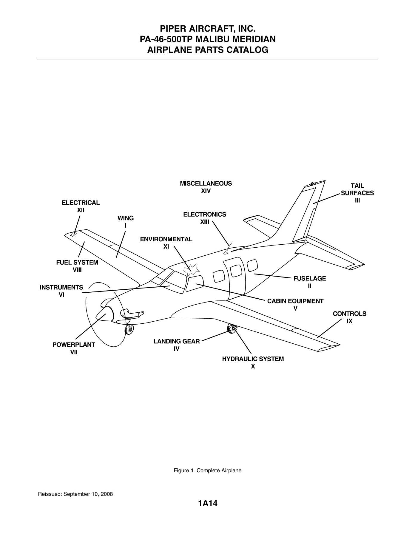
- Section I — Wing Group: Wing Installation, Wing to Fuselage Fairing Installation, Outboard Wing Installation, Aileron Installation, Flap Installation
- Section II — Fuselage Group: Fuselage Assembly Complete, Forward Fuselage Assembly, Fuselage Assembly (F.S. 95 thru 100), Cockpit and Forward Cabin Fuselage, Instrument Panel Support, Center Cabin Fuselage, Aft Cabin Fuselage, Rear Fuselage Assembly, Floorboard Installation, Cabin Entrance Door Installation, Upper Cabin Entrance Door Assembly, Lower Cabin Entrance Door Assembly, Emergency Exit Installation, Windshield and Windows Installation
- Section III — Tail Surfaces Group: Tail Surfaces Installation, Fin Assembly, Rudder Assembly, Stabilizer Assembly, Elevator Assembly
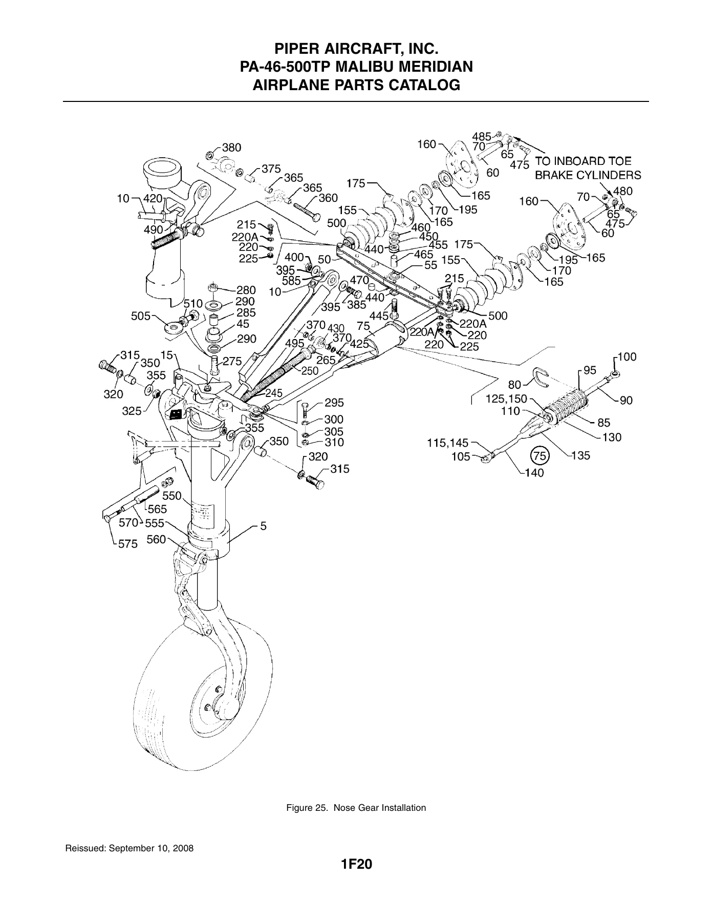
- Section IV — Landing Gear Group: Nose Gear Installation, Nose Gear Locking Actuator, Nose Gear Assembly, Nose Wheel Assembly, Main Gear Installation, Main Gear Assembly, Main Gear Fairing Installation, Main Wheel Assembly, Brake Assembly, Nose and Main Gear Door Actuation Installation, Nose Gear Door Actuator, Brake System Installation, Toe Brake Installation
- Section V — Cabin Equipment Group: Cockpit Finishing Installation, Entertainment Cabinet Installation, Side Panel Installation, Window Frame and Shade Installation, Sun Visor Installation, Cabin Carpet Installation, Seats Installation, Front Seat Assembly, Aft-Facing Seat Assembly, Aft Bench Seat Assembly, Relief Tube Installation
- Section VI — Instruments Group: Instrument Panel Installation (Without Entegra), Instrument Panel Installation (With Entegra), Vacuum System Installation, Pitot Static System Installation (Without Entegra), Pitot Static System Installation (With Entegra)
- Section VII — Power Plant Group: Power Plant Installation, Engine Fire Detection System, Induction System Installation, Plenum Assembly, Oil System Installation, Propeller Installation, Exhaust System Installation, Environmental Protection System, Air Conditioning Installation, Drain System Installation, Accessory Drive Installation, Engine Mount Assembly, Engine Cowling Installation, Engine Controls Installation
- Section VIII — Fuel System Group: Fuel System Installation, Fuel System Installation (4697174 and Up), Fuel Probe Installation
- Section IX — Control System Group: Control Console / Pedestal Installation, Power Lever Assembly, Aileron Control Installation, Rudder Control Installation, Aileron and Rudder Interconnect Installation, Elevator Control Installation, Elevator Trim Installation, Flap Drive Electrical Installation, Flap Drive Mechanical Installation, Control Wheel Installation
- Section X — Hydraulic System Group: Forward Hydraulic System Installation, Center Hydraulic System Installation, Aft Hydraulic System Installation
- Section XI — Environmental Group: Cabin Air System Installation, Cabin Pressurization Control System Installation, Bleed Air and Conditioning System Installation, Air Conditioning Compressor and Freon Lines Installation, Air Conditioning Evaporator and Condenser Installation, Pneumatic Deicing System Installation, Fixed Oxygen Cylinder System Installation, Fixed Oxygen Generator System Installation
- Section XII — Electrical System Group: Forward Electrical System Installation, Fuselage Electrical System Installation, Wing Electrical System Installation, Center Electrical System Installation, Aft Electrical System Installation, Instrument Panel Electrical Installation, Overhead Switch Panel Installation, Pilot Circuit Breaker Panel Installation, Copilot Circuit Breaker Panel Installation, Battery Installation, External Power Installation, Landing Light Installation, Navigation and Strobe Lights Installation, Propeller De-Ice System Installation
- Section XIII — Electronics Group: Antenna, Static Wicks, and Stereo Installation (Standard and Entegra), Emergency Locator Transmitter Installation, Avionics Cooling Installation, Avionics Installation Drawings
- Section XIV — Miscellaneous Group: Placards and Decals Installation, Ground Protection Equipment Installation, Piper Service and Optional Kits, Special Tools, Miscellaneous Hardware and Consumables, Complete Numerical Index
Together, these sections equip maintenance personnel, aircraft operators, and restoration technicians with an exhaustive, part-by-part visual breakdown of the airframe. The manual covers everything from primary structural components, spar caps, and pressure vessel bulkheads to small clips, spacers, bearings, wiring clamps, and environmental ducting, eliminating guesswork when ordering replacement hardware or verifying installed equipment configurations.
Service Publications and Engineering Bulletins Incorporated
A vital feature of this PA-46-500TP Malibu Meridian parts manual is its thorough integration of service publications issued throughout production. The catalog incorporates modifications and replacement kit numbers resulting from numerous factory directives, including:
- Service Bulletins: Incorporates SB 1052 through SB 1202, including SB 1054, SB 1058, SB 1060, SB 1066, SB 1071, SB 1085, SB 1087, SB 1088, SB 1106, SB 1126, SB 1144, SB 1151, SB 1154, SB 1175, SB 1176, SB 1177, SB 1178, SB 1181, SB 1183, SB 1190, SB 1193, and SB 1195.
- Service Letters: Covers updates from SL 1046, SL 1051, SL 1056, SL 1057, SL 1059, SL 1062, SL 1065, SL 1067, SL 1072, SL 1075, SL 1076, SL 1077, SL 1082, SL 1085, SL 1090, SL 1097, SL 1100, SL 1102, SL 1104, SL 1109, and SL 1133.
- Service Spares Letters: Integrates critical spares updates from SSL 167, SSL 425, SSL 430, SSL 431, and SSL 432.
Professional Maintenance Capability and Digital Delivery
Whether you are performing scheduled inspections, rebuilding landing gear assemblies, servicing the environmental pressurization control system, or ordering airframe structural fasteners, having the exact Piper PA-46-500TP Malibu Meridian Airplane Parts Catalog – Part Number 767-004 is essential. Ordering correct replacement components by verified part number prevents maintenance delays, avoids incompatible part orders, and preserves the airworthiness standard of your turboprop aircraft.
This manual is provided as an immediate digital PDF download. Upon checkout, you receive instant access with no shipping wait or physical handling delays. The file is fully compatible with laptops, desktop computers, workshop tablets, and mobile devices across Windows, macOS, iOS, and Android systems. You can zoom in on intricate mechanical line art and high-density exploded diagrams or print specific sections, exploded figures, and part number pages directly for convenient hangar and bench reference.
Reviews
There are no reviews yet.