RAYMOND 21I TRACTOR SCR & RESISTOR PARTS CATALOG MAANUAL – PDF DOWNLOAD
$27.95
RAYMOND 21I TRACTOR SCR & RESISTOR PARTS CATALOG MAANUAL – PDF DOWNLOAD
Description
RAYMOND 21I TRACTOR SCR & RESISTOR PARTS CATALOG MAANUAL – PDF DOWNLOAD
FILE DETAILS:
RAYMOND 21I TRACTOR SCR & RESISTOR PARTS CATALOG MAANUAL – PDF DOWNLOAD
Language : English
Pages : 337
Downloadable : Yes
File Type : PDF
Size:37.7 MB
DESCRIPTION:
RAYMOND 21I TRACTOR SCR & RESISTOR PARTS CATALOG MAANUAL – PDF DOWNLOAD
• Brake and Steering • Elevating/ Attachments
• Drive Unit • Contactors
• Electrical • Special Options (if applicable)
page — the DRIVE MOTOR for this drive unit
on another page — the DRIVE WHEEL for this
unit on another page
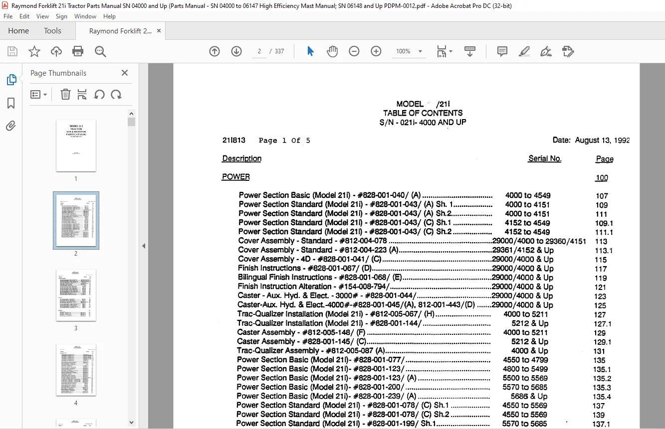
TABLE OF CONTENTS:
RAYMOND 21I TRACTOR SCR & RESISTOR PARTS CATALOG MAANUAL – PDF DOWNLOAD
Power Section Basic (Model 211) – #828-001-040 / (A) 4000 to 4549
Power Section Standard (Model 21i) – #828-001-043/ (A) Sh 1 4000 to 4151
Power Section Standard (Model 21Q – #828-001-043/ (A) Sh2 4000 to 4151
Power Section Standard (Model 21 Q – #828-001-043/ (C) Sh1 4152 to 4549
Power Section Standard (Model 211) -#828-001-043/ (C) Sh2 4152 to 4549
Cover Assembly- Standard – #812-004-078 29000/4000 to 29360/4151
Cover Assembly- Standard – #812-004-223 (A) 29361 /4152 & Up
Cover Assembly- 40 – #828-001-041/ (C) 29000/4000 & Up
Finish Instructions – #828-001-067/ (D) 29000/4000 & Up
Bilingual Finish Instructions – #828-001-068/ (E) 29000/4000 & Up
Finish Instruction Alteration – #154-008-794/ 29000/4000 & Up
Caster-Aux Hyd & Elect -3000# – #828-001-044/ 29000/4000 & Up
Caster-Aux Hyd & E!ect-4000#-#828-001-045/(A), 812-001-443/(D) 29000/4000 & Up
Trac-Oualizer Installation (Model 21 i) – #812-005-067 / (H) 4000 to 5211
Trac-Oualizer Installation (Model 21 i) – #828-001-144/ 5212 & Up
Caster Assembly- #812-005-148/(F) 4000 to 5211
Caster Assembly- #828-001-145/ (C) 5212 & Up
Trac-Oualizer Assembly- #812-005-087 (A) 4000 & Up
Power Section Basic (Model 211)- #828-001-077 / 4550 to 4799
Power Section Basic (Model 21i)- #828-001-123/ 4800 to 5499
Power Section Basic (Model 211)- #828-001-123/ (A) 5500 to 5569
Power Section Basic (Model 211)- #828-001-200/ 5570 to 5685
Power Section Basic (Model 211)- #828-001-239/ (A) 5686 & Up
Power Section Standard (Model 21 I) – #828-001-078/ (C) Sh1 4550 to 5569
Power Section Standard (Model 21 Q – #828-001-078/ (C) Sh2 4550 to 5569
Power Section Standard (Model 21Q -#828-001-199/ Sh1 5570 to 5685
Power Section Standard (Model 211) – #828-001-199/ Sh2 5570 to 5685
Power Section Standard (Model 21 i) – #828-001-238 / (B) Sh1 5686 to 6003
Power Section Standard (Model 21 I) – #828-001-238/ (B) Sh2 5686 to 6003
Power Section Standard (Model 211) – #828-001-238/ (C) Sh1 6004 & Up
Power Section Standard (Model 21 I) – #828-001-238/ (C) Sh2 6004 & Up
Power Section to Mast – #812-000-008/ (K) 29000/4000 & Up
Power Section to Mast – #828-003-278/
Mech Overhead Guard Posts Installation – #828-000-889/ (A) 29000/4000 &”lJp
Mech Overhead Guard Posts Installation – #828-003-869/ 33607 /6148 & Up
Fire Extinguisher Installation – #828-001-436/ 29000/4000 & Up
Back Guard Installation (Rear Guard) -#812-004-175/ (E) 29000/4000 & Up
Back Guard Installation (Full Length) – #100-014-333 (G) 29000/4000 & Up
Rear View Mirror Installation – #828-001-302/ 29000/4000 & Up
Battery Roller Assembly – #828-001-430/ (A) 33372/6004 & Up
Fire Extinguisher Installation – #828-003-727 / 33607 /6148 & Up
Mech Steer Control Assembly – Reverse – #812-004-016 (E) 29000 / 4000 to 32087 / 4549
Mech Steer Control Assembly- Forward – #812-004-017 (F) 29000/4000 to 32087 /4549
Mech Steer Control Assembly- 40 Reverse – #812-004 018 (E) 29000/4000 to 32087 /4549
Mech Steer Cantrel Assembly – 40 Forward – #812-004-019 (E) 29000/4000 to 32087 /4549
Brake & Motor Assembly (Modet 21ij – #812-005-006/ (B) – 4000 to 4549
Brake Assembly- #812-001-541 (C), 400-037 – – 29000/4000 to 34040/6281
Brake Assembly – #828-001-544, 400-060 34041 /6282 & Up
Steering Wheel Assembly- #812-004-150 ; 29000/4000 to_
Steering Wheel Assembly- #828-001-212 (C) _ & Up
Mech Steer Control Assembly – Reverse – #828-001-079 (A) 4550 to 5499
Mech Steer Control Assembly – Reverse – #828-001-265 (A) 5500 & Up
Mech Steer· Contra Assembly – Forward – #828-001-080 (A) 4550 to 5499
Mech Steer Control Assembiy- Forward – #828-001-266 (A) 5500 & Up
Mech Steer Contra Assembly – 40 Reverse- #828-001-081 (A) 4550 to 5499
Mech Steer Contra Assembiy-40 Reverse – #828-001-267 (A) 5500 & Up
Mech Steer Contra Assembly – 40 Forward – #828-001-082 (A) 4550 to 5499
Mech Steer Control Assembly – 40 Forward – #828-001-268 (A) 5500 & Up
Brake & Motor Assembly (Model 21 ij – #828-001-089/ (B) : 4550 & Up
Master Cytfnder Assembly- #812-002-052 29000/4000 & Up
Brake & Motor Assembly (Model 21 EE) – #828-001-490 (A) – 4000 & Up
Steer Assembly Retrofit Kits – #828-900-003, 004, 005, 006 29000/4000 & Up
DRIVE UNIT
Drive Unit Assembly (Model 21 ij – #812-005-007 / (0) 4000 to 4549
Drive Unit Assembly (Model 21 i) – #828-001-088/ 4500 to 5211
Drive Unit Assembly (Model 21 ij – #828-001-088/ (C) 5212 & Up
Bearing Assembly- #812-001-230 (E), 812-001-231 (0) 29000/4000 & Up
Drive Wheel Assembly- #812-000-279 (8), 812-000-299/ (0) 29000/4000 to 31507 /5211
Drive Wheel Assembly – #828-001-148/ (A) – – 31508/5212 & Up
Drive Motor Assembly (Modef 21 ij _- Prestollte – #570-440 4000 to 4549
Drive Motor Assembly (Modet 211) – Prestollte – #570-251 /200 4550 & Up
Drive Motor Assembly (Modet 21 ij – Prestolfta – #570-251 /201 4550 & Up
Drive Motor Assembly (Model 21 ij – GE – #570-251/100 4550 & ‘1Jp
Drive Motor Assembly (Modet 21 Q -Advanced DC – #570-251 /500 4550 & Up
Drive Unit Assembly (Model 21EE) – #828-001-489/ (A) 4000 & Up
EL,ECTBICAL
Sectrical Symbol _____,
Wiring Diagram – #154-008-781 (L) Sh 1 2M00/4000 & Up
Wiring Diagram – #154-008-781 (L) Sh 2 291)()()/4000 & Up
Wiring Diagram – #154-008-781 (L) Sh 3 2M00/4000 & Up
Wiring Diagram – #154-008-781 (L) Sh 4 29000/4000 & Up
Electrical Schematic· #154-008-782 (K) Sh 1 ·–·-···············29000/4000 & Up
Electrical Schematic – #154-008-782 (K) Sh 2 29000/4000 & Up
System Electrical – #154-008-780/ (J) Sh 1 29000/4000 to 32244/5569
System Electrical – #154-008-780/ (J) Sh 2 29000/4000 to 32244/5569
System Electrical – #154-008-780/ (L) Sh 1 32245/5570 to 32884/5685
System Electrical – #154-008-780/ (L) Sh 2 32245/5570 to 32884/5685
System Electrical – #154-008-780/ (P) Sh 1 32885/5686 to 33417 /6036
System Electrical – #154-008-780/ (P) Sh 2 32885/5686 to 33417 /6036
System Electrical – #154-008-780/ (T) Sh 1 33418/6037 & Up
System Electrical – #154-008-780/ (T) Sh 2 33418/6037 & Up
SCR Panel Assembly- #154-008-725/ (G) 29000/4000 & Up
Electrical Power Filter Assembly-#154-008-862 (C) 29000/4000 & Up
Electric Control Assembly- #154-008-723/ (8) 29000/4000 to
Electric Control Assembly- #154-008-723/ (E) & U-p-
Mechanical Control Assembly- #154-008-724 (H) –& Up
Handle Assembly- #154-002-542/ (L) 29000/4000 to
Handle Assembly – #812-010-201 / (8) _ & Up–
Panel Assembly- #812-004-146 (C) 29000/4000 & Up
Elect Batt Conn Installation – #154-008-790/ (B) 29000/4000 & Up
Elec Connector Assembly- #154-008-n5/ (C) 29000/4000 & Up
Indicator Light Assembly – #154-008-950/ (A) 29000/4000 & Up
Switch Assembly- #154-008-960/ 29000/4000 & Up
Meter Installation -Curtis Fuel Gauge – #154-008-787 (C) 29000/4000 & Up
Back-Up Lamp Assembly- #154-008-958/ 29000/4000 & Up
Light Rework – #154-007-255 (RIE1), 154-008-963 29000/4000 & Up
System Elect Supplement Remote – #154-008-785/ (G) 29000/4000 & Up
Remote Assembly- #154-010-023 29000/4000 & Up
Wiring Supplement- #154-010-024 29000/4000 & Up
Discharge Indicator Installation – #154-008-955/ 29000/4000 & Up
Working Light Installation – #154-008-965/ (A) 29000/4000 & Up
Light Assembly- #812-002-021 (A), 812-005-080 29000/4000 & Up
EE Conversion Kit Installation – #828-001-055/ (8) 29000/4000 to 32884/5685
EE Conversion Kit Installation – #828-001-055/ (0) ·—···········32aas/5686 & Up
Limit Switch Install – 24 High Speed RH – #154-007-235/ (RIE3) 29000/4000 & Up
Limit Switch Install -24 High Speed LH -#154-007-236/ (RIE3) 29000/4000 & Up
Limit Switch Install – 20 High Speed RH – #154-007-237 / (RIE3) 29000/4000 & lJp
Limit Switch Install – 20 High Speed LH – #154-007-238/ (RIE3) 29000/4000 & Up
Elec Limit Switch Installation – #625-000-260/ (RIE3) 29000/4000 & Up
Contactor Assembly-36V Remote- #1-105-079 4000 & Up
Contactor Assembly (M, P, X) 36V – #154-008-740/ 4000 to 5569
Contactor Assembly (M, P, X) 36V – #154-010-740/ 5570 & Up
Contactor Assembly (F & R) 36V- #154-008-742/ 4000 to 5569
Contactor Assembly (F & R) 36V – #154-010-742/ 5570 & Up
Resistor Assembly Installation – #828-000-980/ (G) 29000/4000 & Up
Resistor Assembly- EE – #812-002-915/ (A) 29000/4000 & Up
Resistor Assembly- E – #812-002-905 (8) 29000/4000 & Up
Electric Fan Installation – #828-001-437 / (A) 29000/4000 & Up
Heavy Duty Traction Motor- #812-900-200/ (A) 4000 & Up
Working Lights Installation – #828-003-n3/ 33607 /6148 & Up
Light Rework – #828-003-728/ 33607 /6148 & Up
Strobe Light Installation – #828-003-n5/ 33607 /6148 & Up
Strobe Light Assembly – #828-003-730/ _____ 33607 /6148 & Up
Warning Lights Installation – #828-003-nS/ (A) –············33607 /6148 & Up
Warning Ught Installation – #154-005-638/ 33607 /6148 & Up
Back-Up Alarm Installation – #828-003-780/ 33607 /6148 & Up
Back-Up Ughts Installation – #828-003-786/ 33607 /6148 & Up
All Travet Alann lnstalJatfon #828-003-788/ 33607 /6148 & Up
Fan Assembly· #828-003-796/ 33607 /6148 & Up
HYORAULJC
Standard Hydraulic Symbas
Hydraulic Schematic – #812-004-134 (C) 29000/4000 to 30664/4799
Hydraulic Schematic – #828-001-121 (8) 30665/4800 & Up
System Hydraulic – #828-001-051 / (0) 29000/4000 to 30664/4799
System Hydraulic – #828-001-120/ (G) : 4800 & Up
System Hydraulic – Straddle w/Aux – #828-001-053/ (C) 29000/4000 to 30664/4799
Manifold Assembly- #812-004-166/ (G) 29000/4000 to_:_
Manifold Assembly – #812-004-166/ (H) _ & Up
Lift/Lower Manifold – #520-825/ 29000/4000 to
Lift/Lower Manifold #520-845/ & Up
Auxiliary Valve Assembly- 1 Spool· #812-002-169 (F) 29000/4000 & Up
Valve Assembly- 2 Spool – #828-001-049 (C)·—········ 29000/4000 & Up
Valve Assembly-3 Spool – #828-001-050 (8) 29000/4000 & Up
Valve Assembly· #828-001-000/ (A)–····· ···············—-····29000/4000 & Up
Auxiliary Valve Assembly – 2 Spool – #812-002-170 (D)—··············29000/4000 & Up
Auxiliary Valve Assembly – 3 Spool – #828-001-038 (A) 29000/4000 & Up
Control Valve Assembly· 1 Spool – #520-075 29000/4000 & Up
Control Valve Assembly- 2 Spool – #520-076/520-078 29000/4000 & Up
Control Valve Assembly- 3 Spool – #520-077 /520-079 29000/4000 & Up
Control Valve Assembly (Lift) – #812-004-141 (C) 29000/4000 & Up
Auxiliary Pump and Motor Assembly – (Modal 21 Q – #812-005-010 (E) 4000 & Up
Auxiliary Motor Assembly- (Modal 21Q -Prestollte- #570-442/100 4000 & Up
Auxiliary Motor Assembly – (Modal 21 ij – Warfield – #570-442/150 4000 & Up
Auxiliary Motor Assembly – (Modal 21 ij – GE – #570-442/200 4000 & tJp
Auxiliary Pump Assembly- #500-417 /100 29000/4000 & Up
Auxiliary Pump Assembly- #500-417 /200 29000/4000 & Up
Auxiliary Pump Assembly – #500-417 /201 29000/4000 & Up
Lift Pump and Motor Assembly- EE – #812-002~4 (E) 29000/4000 to 32884/5685
Lift Pump and Motor Assembly – (Modal 21 Q – #812-005-009 (E) 4000 to 4549
Lift Motor Assembly – GE – #570-427 /101 29000/4000 to 32884/5685
Lift Motor Assembly- Prestolite – #570-427 /201 29000/4000 to 32884/5685
Lift Motor Assembly- Hitachi- #570-427 /400 29000/4000 to 32884/5685
Lift Motor Assembly – GE – (Model 21 Q #570-217 /100 ······—-· 4000 to 5685
Lift Motor Assembly – Prestolite – (Model 211) #570-217 /200 ····—· 4000 to 5685
Lift Motor Assembly – Warfield – (Model 211) #570-217 /150 ········— 4000 to 5685
Lift Motor Assembly – Advanced DC- (Mode 21 i) – #570-257 /500 5686 & Up
Lift Motor Assembly – Prestolite (EE)- (Model 211) – #570-257 /200—- 5686 & Up
Lift Pump Assembly- EE – 500-344 29000/4000 to 32884/5685 571
Lift Pump Assembly – (Model 21 i) – #500-423/ 4000 & Up 575
Reservoir Assembly- #812-004-024 29000/4000 to 32884/5685 577
Reservoir Assembly – #828-001-274 (B) 32885/5686 & Up 5n1
Hydraulic Ram Feed Line Installation – #812-005-061/ 29000/4000 & Up 579
Hydraulic Ram Feed Line Installation – #812-005-172/ (C) 29000/4000 to 33606/6147 5791
Hydraulic Ram Feed Line Installation – #828-003-762/ 33607 /6148 & Up 5792
Motor Steer Assembly- #812-002-623 (F) 29000/4000 to 32087 /5499 581
Motor Steer Assembly – #828-001-254 32088/5500 & Up 5811
Lift Pump and Motor Assembly (Model 21 i) – #828-001-085 4550 to 5685 585
Lift Pump and Motor Assembly (Model 21 i) – #828-001-223 (D) 5686 & Up 5851
Valve Assembly- R/R w/Equalizing – #154-008-971 (A) 30665/4800 & Up 587
Travel R/R Manifold w/Equalizing- #520-840 30665/4800 & Up 589
Valve Assembly- R/R w/o Equalizing- #154-008-975 (A) 30665/4800 & Up 591
Travel R/R Manifold w/o Equalizing- #520-842 30665/4800 & Up 593
Lift Pump and Motor Assembly- Model 21EE – #828-001-491 (A) 5686 & Up 597
Auxiliary Pump and Motor Assembly (Model 21 EE) – #828-001-488 5686 & Up 5101
IMAGES PREVIEW OF THE MANUAL:
Customer Support: [email protected]
PLEASE NOTE:
- This is the SAME exact manual used by your dealers to fix your vehicle.
- The same can be yours in the next 2-3 mins as you will be directed to the download page immediately after paying for the manual.
- Any queries / doubts regarding your purchase, please feel free to contact [email protected]
S.M