Raymond 6210 Walkie Straddle Stacker Maintenance Manual SN 621-15-00100 & Up – PDF DOWNLOAD
Original price was: $86.95.$28.95Current price is: $28.95.
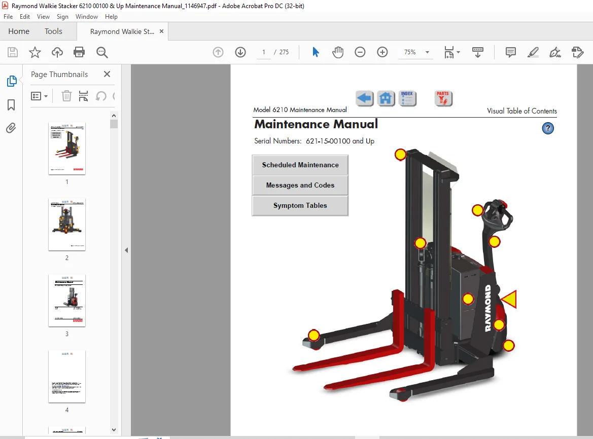
Raymond 6210 Walkie Straddle Stacker Maintenance Manual SN 621-15-00100 & Up – PDF DOWNLOAD
Description
Raymond 6210 Walkie Straddle Stacker Maintenance Manual SN 621-15-00100 & Up – PDF DOWNLOAD
FILE DETAILS:
Raymond 6210 Walkie Straddle Stacker Maintenance Manual SN 621-15-00100 & Up – PDF DOWNLOAD
Language : English
Pages : 275
Downloadable : Yes
File Type : PDF
DESCRIPTION:
Raymond 6210 Walkie Straddle Stacker Maintenance Manual SN 621-15-00100 & Up – PDF DOWNLOAD
Manual Design:
- This manual is designed to give personnel, with an expected level of expertise, the technical information necessary to maintain, troubleshoot, and repair a Raymond product.
- The two-line running page header at the top of each page contains the name of the manual, the title of the current section, and the topic of the current page.
This manual includes the following sections:
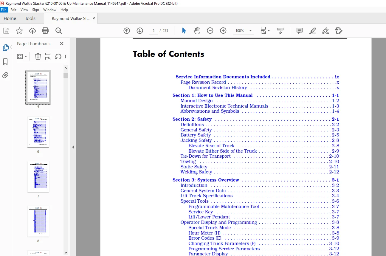
TABLE OF CONTENTS:
Raymond 6210 Walkie Straddle Stacker Maintenance Manual SN 621-15-00100 & Up – PDF DOWNLOAD
Service Information Documents Included ix
Page Revision Record x
Document Revision History x
Section 1: How to Use This Manual 1-1
Manual Design 1-2
Interactive Electronic Technical Manuals 1-3
Abbreviations and Symbols 1-4
Section 2: Safety2-1
Definitions 2-2
General Safety 2-3
Battery Safety 2-5
Jacking Safety 2-8
Elevate Rear of Truck 2-8
Elevate Either Side of the Truck 2-9
Tie-Down for Transport 2-10
Towing 2-10
Static Safety 2-11
Welding Safety 2-12
Section 3: Systems Overview 3-1
Introduction3-2
General System Data 3-3
Lift Truck Specifications 3-4
Special Tools3-6
Programmable Maintenance Tool 3-7
Service Key 3-7
Lift/Lower Pendant3-7
Operator Display and Programming 3-8
Special Truck Mode3-8
Hour Meter (H)3-8
Error Codes (E) 3-9
Changing Truck Parameters (P) 3-10
Programming Service Parameters 3-12
Parameter Display3-12
Setting Individual PIN-Key Codes 3-13
Display Part Numbers (Pn) 3-19
Display Test (d) 3-19
Service Input/Output Display 3-20
Digital Inputs/Outputs from Traction Amplifier and VM3-21
Traction Amplifier System Mode 3-23
Modes of Operation 3-24
Programmable Maintenance Tool (PMT)3-24
Monitor Mode 3-24
Faults Mode 3-25
Clear 3-25
Information Mode3-25
Programmer Mode3-25
Table of Contents Model 6210 Maintenance Manual
ii Publication: 1146947, Revised: 12 Jan 2017
FlashWare 3-27
Overview 3-27
Requirements 3-27
Installing FlashWare on PC 3-27
Connecting PC to Truck3-27
Starting FlashWare 3-27
Section 4: Scheduled Maintenance 4-1
Scheduled Maintenance Guidelines 4-2
Initial 90 Day/250 Deadman Hour (HD) Maintenance 4-3
Every 180 Days or 500 Deadman Hours (HD) 4-4
Every 360 Days or 2000 Deadman Hours (HD) 4-6
Lubrication Points4-7
Chain Maintenance 4-8
Fork Inspection 4-9
Section 5: Troubleshooting5-1
List of Troubleshooting Charts and Tables 5-2
Electrical Troubleshooting Guidelines 5-1
General 5-1
Shorts to Frame 5-1
DC Electric Motor5-4
DC Motor Types 5-4
Inspection 5-4
Servicing5-4
Open Circuit Motor Test5-7
Grounded Motor Test 5-7
Short-Circuited Armature 5-7
Short-Circuited Winding5-8
AC Electric Motors 5-9
AC Motor Type5-9
Open Winding5-9
Shorted Winding 5-9
Hydraulic Troubleshooting Guidelines5-10
Symptom Tables: Travel System (Forward/Reverse) 5-11
No travel in either direction, lift/lower okay
(Code E106, Digital output overcurrent) 5-11
No travel in either direction, lift/lower okay
(Code E201, M-error) 5-11
No travel in either direction, lift/lower okay
(Code E214, Traction Amplifier CAN timeouts) 5-12
Slow travel, lift/lower okay No fault codes 5-12
No travel 5-12
Slow or no travel (Code C41, Battery under-voltage warning)5-12
Slow or no travel (Code C43, Traction Amplifier
thermal cutback)5-13
No travel (Code C42, Battery over-voltage warning) 5-13
Truck does not accelerate correctly 5-14
No Travel or Slow Travel TA Flash Code 2,2, (Thermal
Cutback) Heatsink Temperature Exceeded 185°F (85°C)
Operator Display May Indicate Hot2 (C45) 5-14
No Travel, No Lift/Lower TA Flash Code 3,1
Operator Display May Indicate Error Code E1065-14
Model 6210 Maintenance Manual Table of Contents
Publication: 1146947, Revised: 12 Jan 2017 iii
No Travel, Main Contactor Does Not Close TA Flash Code 3,9
Operator Display Indicates Error Code E107 5-15
No Travel, No Lift/Lower TA Flash Code 1,2
Operator Display Indicates Error Code E201 5-15
No Travel, No Lift/Lower TA Flash Code 1,3
Operator Display Indicates Error Code E202 5-15
No Truck Functions Active TA Flash Code 1,7, (Low
Battery Voltage) Operator Display May Indicate E2215-15
No Truck Functions Active TA Flash Code 1,8, (Excessive
Battery Voltage) Operator Display May Indicate E2225-16
Symptom Tables: Wiring System5-17
Truck functions partially, some functions do work
when commanded 5-17
Symptom Tables: Electrical Problems5-18
Green and red LEDs on keypad do not light when a
button on the keypad is pushed (keypad option only) 5-18
Horn does not sound when horn button is pushed5-18
Battery discharge indicator (BDI) will not reset to 100%5-18
Charger Troubleshooting 5-19
Section 6: Messages and Codes 6-1
List of Messages and Codes 6-2
Caution and Error Codes 6-5
Messages and Caution Codes 6-6
Code ‘GATE’ 6-6
Code ‘TEST’ 6-6
Code ‘SLO’ 6-6
Code ‘Sro’ (C14) 6-7
Code ‘LoGn’ (C15) (iWAREHOUSE Only) 6-7
Code br_o (C16) 6-7
Code C196-8
Code HPd (C20) 6-8
Code C266-8
Code C276-9
Code C306-9
Code C316-9
Code C32 6-10
Code C33 6-10
Code C35 6-10
Code Lo (C41) 6-11
Code Hi (C42) 6-11
Code Cold (C43) 6-12
Code Hot1 (C44) 6-12
Code Hot2 (C45) 6-13
Code C46 (iWAREHOUSE® Only) 6-13
Code C47 (iWAREHOUSE® Only) 6-13
Code C48 6-14
Code C57 6-14
Code C60 6-14
Code C61 6-15
Code C62 6-15
Code C64 6-15
Code C66 6-16
Table of Contents Model 6210 Maintenance Manual
iv Publication: 1146947, Revised: 12 Jan 2017
Code C67 6-16
Code C68 6-16
Code C70 6-17
Code C71 6-17
Code C72 6-17
Code 075 6-18
Code C95 6-18
Code C96 6-18
Code C97 6-19
Code C98 6-19
Code AC (C256) 6-19
Code C257 6-20
Code C258 6-20
Code C259 6-20
Code C380 6-21
Code C381 6-21
Code C382 6-21
Code C383 6-22
Code C384 6-22
Code C385 6-22
Code C386 6-23
Code C395 6-23
Code C405 6-23
Error Codes 6-24
Code E101 6-24
Code E106 6-24
Code E107 6-25
Code E108 6-25
Code E109 6-25
Code E140 6-26
Code E141 6-26
Code E142 6-26
Code E150 6-27
Code E151 6-27
Code E152 6-27
Code E157 6-28
Code E159 6-28
Code E160 6-28
Code E201 6-29
Code E202 6-29
Code E203 6-29
Code E220 6-30
Code E221 6-30
Code E222 6-30
Code E223 6-31
Code E224 6-31
Code E225 6-31
Code E228 6-32
Code E230 6-32
Code E232 6-32
Code E233 6-33
Code E235 6-33
Model 6210 Maintenance Manual Table of Contents
Publication: 1146947, Revised: 12 Jan 2017 v
Code E236 6-33
Code E248 6-34
Code E249 6-34
Code E250 6-34
Code E251 6-35
Code E254 6-35
Code E690 6-35
Code E691 6-36
Code E700 6-36
Code E901 6-36
Code E996 6-37
Code E997 6-37
Code E998 6-37
Code E999 6-38
Code BTLR 6-38
Traction Amplifier Flash Codes 6-39
Delta-Q Charger Codes 6-41
Section 7: Component Procedures 7-1
List of Component Procedures 7-2
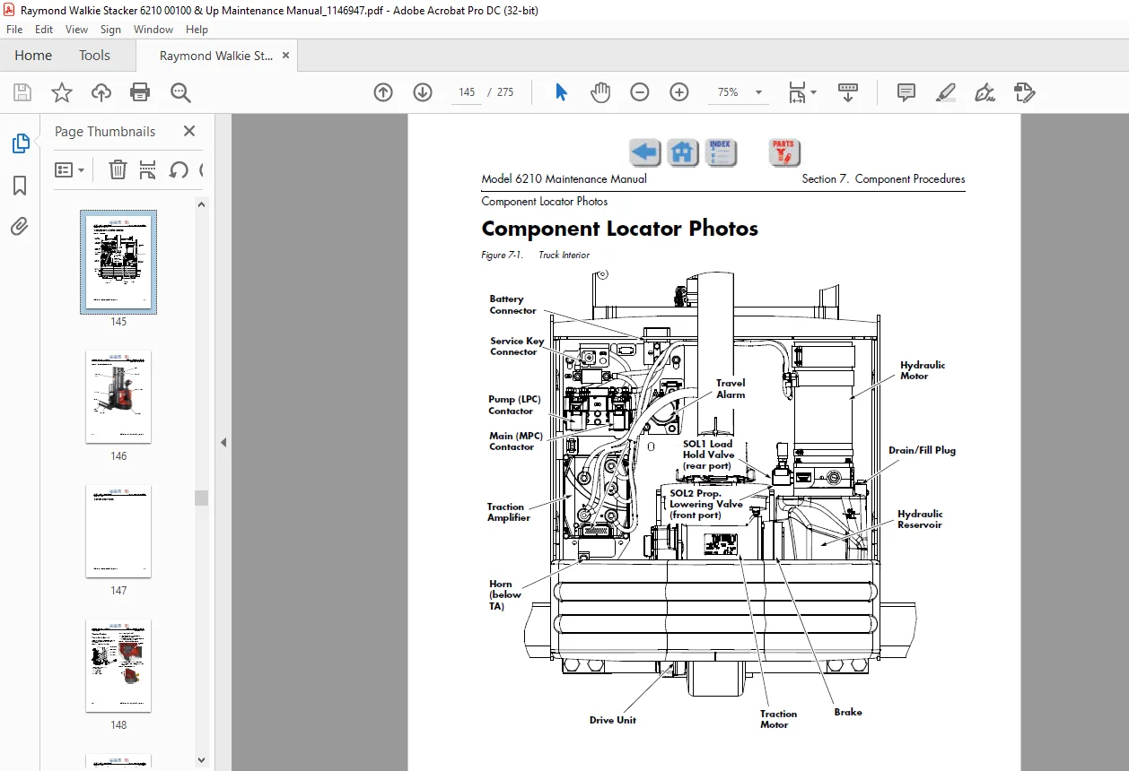
Component Locator Photos 7-1
Covers and Finish 7-3
Tractor Covers 7-4
Tractor Cover Removal 7-4
Tractor Cover Installation 7-6
Tractor Bumper 7-9
Bumper Removal 7-9
Bumper Installation7-9
Steering and Controls 7-11
Control Arm Assembly7-12
Control Arm Removal 7-13
Control Arm Installation 7-13
Control Head Assembly 7-15
Control Head Removal 7-16
Control Head Installation 7-17
Keypad 7-18
Keypad Removal 7-18
Keypad Installation 7-19
Drive and Brake 7-21
Drive Unit Assembly 7-22
Drive Unit 7-24
Drive Unit Removal 7-24
Drive Unit Disassembly7-25
Drive Unit Assembly 7-25
Drive Unit Installation 7-26
Drive Unit Housing Lubrication 7-27
Drive Wheel7-28
Drive Wheel Removal 7-28
Tire Replacement 7-29
Drive Wheel Installation7-30
Electromagnetic Brake Assembly7-31
Brake Disc Location 7-31
Table of Contents Model 6210 Maintenance Manual
vi Publication: 1146947, Revised: 12 Jan 2017
Air Gap Inspection7-31
Friction Disc Replacement 7-31
Electric Brake Release 7-32
Mechanical Brake Release 7-32
Electrical Components 7-33
Battery 7-34
Swing-out Battery Pack7-34
Charger Replacement 7-36
Removal (Industrial Battery)7-38
Installation (Industrial Battery) 7-38
Inspection and Care 7-38
Battery Connector 7-43
Inspection 7-43
Cable Removal, Replacement, and Installation 7-43
Power Cables 7-45
Power Cable Repair 7-45
Wiring Harness 7-47
Wiring Harness Terminology7-47
Wiring Harness Inspection 7-47
Wiring Harness Repair 7-48
Wiring Harness Soldering Procedures 7-48
Fuses7-49
Fuse Test/Inspection 7-49
Horn 7-50
Horn Removal 7-50
Horn Installation 7-50
Traction Amplifier 7-51
Motor Circuit7-51
Control Circuit 7-51
Maintenance7-52
Safety 7-52
Diagnostics and Troubleshooting 7-52
To Clean the Traction Amplifier 7-52
Traction Amplifier Removal 7-53
Traction Amplifier Installation 7-53
Contactors7-54
Resistance Testing7-54
Contactor Removal 7-54
Contactor Installation 7-54
Switches 7-55
General7-55
Testing/Inspecting Switches7-55
Main ON/OFF Switch 7-55
2-Position Keyed Switch (Optional) 7-56
Arm Angle Proximity Switch 7-56
Converting from Keypad 7-58
DC Motors, General 7-59
Motor Brush Inspection7-59
Motor Brush Replacement 7-59
Motor Brush Spring Tension7-60
Terminal Nuts 7-61
Polishing the Commutator 7-61
Model 6210 Maintenance Manual Table of Contents
Publication: 1146947, Revised: 12 Jan 2017 vii
Traction Motor 7-62
Traction Motor Disassembly 7-64
Traction Motor Assembly 7-64
Lift Motor 7-67
Lift Motor Removal7-67
Lift Motor Installation 7-67
Lift Motor Brush Replacement 7-67
Hydraulic Components 7-69
Hydraulic System 7-70
Hydraulic Diagram and Components 7-70
Main Components7-70
Hydraulic Unit Torque Specifications 7-71
Hydraulic Unit 7-72
Reservoir 7-74
Reservoir Removal7-74
Reservoir Inspection 7-74
Reservoir Installation 7-74
Hydraulic Fluid Level Check7-75
Changing Hydraulic Fluid 7-75
Hydraulic Pump7-76
Hydraulic Pump Removal 7-76
Hydraulic Pump Installation7-76
Filter Screen 7-77
Removal7-77
Inspection 7-77
Installation 7-77
Lift Cylinder 7-78
Removal7-78
Disassembly/Assembly7-78
Installation 7-79
Mast, Chain, Hose, Cable7-81
Main Mast 7-82
Guidance Damper7-82
Adjusting Mast Guides/Dampers 7-83
Carriage Removal and Mast Disassembly 7-84
Outrigger Assembly 7-85
General7-85
Maintenance7-85
Support Arm Width Adjustment 7-85
Load Wheels 7-88
Load Wheel Removal 7-88
Load Wheel Installation7-88
Lift Chain 7-90
Lift Chain Adjustment 7-90
Options 7-91
Cold Storage Conditioning 7-92
Cold Storage Hydraulic Fluid7-92
Travel Alarm 7-93
Flashing Light 7-93
Table of Contents Model 6210 Maintenance Manual
viii Publication: 1146947, Revised: 12 Jan 2017
Section 8: Theory of Operation 8-1
Definitions 8-2
Acceleration 8-2
Arm Angle Proximity Switch 8-2
Click-to-Creep8-2
Continuity 8-2
Controller Area Network (CAN)8-2
Creep Speed 8-2
Current Limiting 8-2
Deceleration 8-3
Emergency Reverse8-3
Fault Codes 8-3
Open Circuit 8-3
Overvoltage Cutoff 8-3
PIN-Key Code8-3
Pulse Width Modulation8-3
Regenerative Braking 8-3
Short-Circuit or Short 8-4
Speed Limiting 8-4
Thermal Cutback (Traction Amplifier) 8-4
Tractor 8-4
Truck Off Delay (Keypad only)8-4
Undervoltage Cutoff8-4
Vehicle Manager 8-4
Direction/Speed Control 8-5
Control Arm Positioning 8-5
Travel Request, Forks Trailing8-5
Travel Request, Forks-First 8-5
Emergency Reverse8-6
Truck Starting 8-6
Lift/Lower System8-7
Lift8-7
Lower 8-7
Traction System 8-8
Vehicle Manager 8-8
Traction Amplifier 8-8
Pinout Matrix 8-9
Section A: Appendix A-1
Lubrication Equivalency Chart A-2
Thread Adhesives, Sealants, and LubricantsA-3
Component Specific Service/Torque Chart A-4
Torque Chart – Standard (Ferrous) A-5
Torque Chart – Standard (Brass) A-6
Torque Chart – Metric (Ferrous) A-7
Torque Chart – Metric (Brass) A-8
Torque Chart – Thread Forming ScrewsA-9
Torque Chart – Hydraulic Fittings A-11
Torque Chart – Straight Thread Face Seal O-Rings A-12
Decimal Equivalent Chart A-13
Standard/Metric Conversions A-15
Section I: Index I-1
Questions? Email us: [email protected]
https://vimeo.com/834959181?share=copy
IMAGES PREVIEW OF THE MANUAL:
PLEASE NOTE:
- This is the SAME manual used by the dealers to troubleshoot any faults in your vehicle. This can be yours in 2 minutes after the payment is made.
- Contact us at [email protected] should you have any queries before your purchase or that you need any other service / repair / parts operators manual.
S.V