★ TRUSTED BY 321,897+ PROFESSIONALS WORLDWIDE
🏢
Trusted Business
Verified & Licensed
🛡️
Virus Free Files
100% Safe Downloads
🔒
Secure Payment
SSL Protected
⚡
Instant Delivery
Available Immediately
Sale!

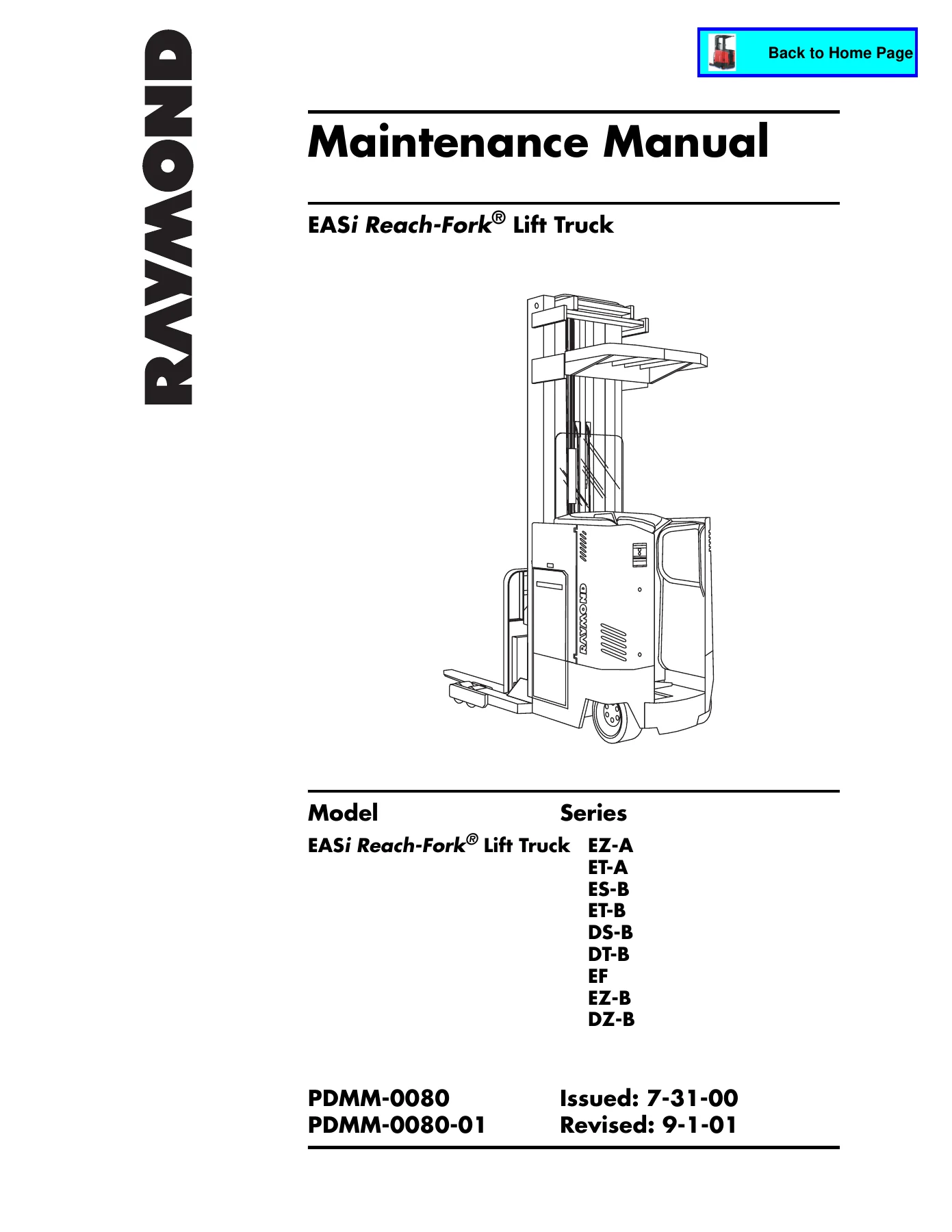
Raymond EASi Reach-Fork Lift Truck Maintenance Manual PDMM-0080 – EZ ET ES DS DT EF DZ Series

Original price was: $39.95.Current price is: $23.95.

Complete Raymond EASi Reach-Fork lift truck maintenance manual PDMM-0080 for Series EZ-A, ET-A, ES-B, ET-B, DS-B, DT-B, EF, EZ-B and DZ-B. Covers scheduled maintenance, troubleshooting, fault codes, component procedures, theory of operation, electrical schematics and hydraulic schematics in 746 pages.

⚡
Instant PDF Download
Available immediately
💾
Save to Your Device
Download & keep forever
🛡️
Antivirus Scanned
100% virus-free
🌍
Trusted Worldwide
175,000+ customers

Description

Raymond EASi Reach-Fork Lift Truck Maintenance Manual – PDMM-0080

This is the complete Raymond EASi Reach-Fork Lift Truck Maintenance Manual, document number PDMM-0080 (PDMM-0080-01), originally issued 7-31-00 and revised 9-1-01. It is the full-service reference used to keep EASi Reach-Fork trucks running correctly, from routine scheduled maintenance through component-level repair, electrical fault diagnosis and hydraulic system troubleshooting. Every chapter needed to service the truck is here: safety, systems overview, scheduled maintenance intervals, symptom-based troubleshooting, fault codes and electrical tests, step-by-step component procedures, theory of operation and full schematics in the appendix.

File Details

  • Manual type: Maintenance Manual
  • Brand: Raymond (The Raymond Corporation)
  • Model line: EASi Reach-Fork Lift Truck
  • Series covered: EZ-A, ET-A, ES-B, ET-B, DS-B, DT-B, EF, EZ-B, DZ-B
  • Language: English
  • Page count: 746 pages
  • File format: PDF
  • Document number: PDMM-0080 / PDMM-0080-01
  • Issued: 7-31-00
  • Revised: 9-1-01

Chapters Covered

The Raymond EASi Reach-Fork Lift Truck Maintenance Manual PDMM-0080 is organized into the following top-level chapters, each with their own sub-sections:

  • How to Use This Manual – Map of the Manual, Manual Design, Page Revision Record, Service Bulletins Included, Product Improvement Notices Included, START Page
  • Safety – Definitions, General Safety, Battery Safety, Static Precautions, Jacking Safety, Tie-down for Transport, Welding Safety
  • Systems Overview – Introduction, Lift Truck Specifications, Operator Displays, Modes of Operation
  • Scheduled Maintenance – Maintenance Guidelines, Operator’s Daily Checklist, Every 60 Days/250 Deadman Hours, Every 90 Days/600 Hours, Every 180 Days/1500 Hours, Every 360 Days/3000 Hours, Scheduled Maintenance Points, Motor Maintenance, Maintenance Minder Tool, Lubrication Points
  • Troubleshooting – How to Use This Chapter, Electrical Troubleshooting Guidelines, Electrostatic Discharge, Shorts to Frame Test, Hydraulic Troubleshooting Guidelines, Troubleshooting Procedure, Symptom Tables for Hydraulic Functions, Travel Functions and Electrical Symptoms
  • Messages, Codes, and Tests – Firmware Changes, Modes of Operation, Messages and Codes Summary List, Messages and Codes Summary Tables, Electrical Codes, Electrical Connector Locator Chart, Circuit Card Connectors, Electrical Test Summary List, Analog Tests, Digital Input Tests, Digital Output Tests
  • Component Procedures – Component Locator Photos, Covers and Finish, Steering and Controls, Drive and Brake, Electrical Components, Hydraulic Components, Mast/Chain/Hose and Cable, Options
  • Theory of Operation – Traction System Functional Operation, Operation of the Travel System, Brake System, Steering System, Lift/Lower System Functional Operation, Auxiliary System, 4-D Control
  • Appendix – Lubrication Specification Chart, Thread Adhesives/Sealants/Lubricants, Torque Charts (Standard Ferrous, Metric Ferrous, Standard Brass), Decimal Equivalent Chart, Standard/Metric Conversions, Electrical Schematics, Hydraulic Schematics
  • Index

In practice, this Raymond EASi Reach-Fork maintenance manual gives a technician a single reference for the entire truck platform. The electrical fault-code chapter alone covers dozens of codes – from Code 12 (lift motor temperature hot) through the PC, P, B and X contactor codes, VFC and System Card faults, and 4-D caster/steer faults – each with alarm behaviour, system response, how to clear, and the specific tests to run. The analog, digital input and digital output tests give measurable values so diagnosis is not guesswork. On the mechanical side, the component procedures walk through real teardown and reassembly of the drive unit, drive motor, brake, control handle, lift pump, auxiliary pump, steering pump, main manifold, reach cylinder, tilt cylinder, sideshift cylinder, lift cylinders and the full mast assembly. The appendix schematics and torque charts mean every fastener and hose can be reassembled to Raymond’s original specifications.

What This Manual Helps You Do

With the Raymond EASi Reach-Fork service information in this PDF you can carry out scheduled maintenance on all covered EASi Reach-Fork series, read and clear fault codes correctly, troubleshoot travel, lift, lower, steer, reach, tilt, sideshift and 4-D caster issues using the symptom tables and tests, remove and reinstall major components, replace brake pads and rotors to the published gaps, adjust caster height and mast backlash, service the hydraulic system and bleed it properly, and check electrical shorts to frame before they damage the System Card or VFC. Correct procedures and published torque and gap values matter on reach trucks: an over-shimmed mast binds, a mis-adjusted brake drags and overheats the drive motor, and a wrong brake rotor/pad gap can turn a routine repair into a component replacement. This document exists so those values are on hand rather than guessed.

Complete PDF Bookmark Tree

Complete Bookmarks

The complete bookmarks in the “Raymond EASi Reach-Fork Lift Truck Maintenance Manual PDMM-0080 – EZ ET ES DS DT EF DZ Series” are as follows:

EASi Reach-Fork® Lift Truckp. 1
How to Use This Manualp. 3
Map of the Manualp. 4
Design of the Manualp. 5
Page Revision Recordp. 7
Service Bulletins Includedp. 9
Product Improvement Notices Includedp. 10
Table of Contentsp. 13
How to Use This Manual 1-1p. 13
Safety 2-1p. 13
Systems Overview 3-1p. 13
Scheduled Maintenance 4-1p. 13
Troubleshooting 5-1p. 13
Messages, Codes, and Tests 6-1p. 14
Component Procedures 7-1p. 14
Theory of Operation 8-1p. 14
Appendix A-1p. 14
Index I-1p. 15
START Pagep. 17
Safetyp. 19
Definitionsp. 20
General Safetyp. 21
Battery Safetyp. 25
Static Precautionsp. 29
Figure 2-1: ESD Ground Jackp. 29
Figure 2-2: Anti-Static Kit with Wrist Strap and Matp. 30
Jacking Safetyp. 31
Figure 2-3: Verify A-frame Down-Travel Adjustment Boltp. 31
Figure 2-4: Correct Jacking Locationsp. 32
To elevate the rear of the lift truck:p. 32
To elevate either side of the lift truck:p. 32
Tie-down for Transportp. 32
Welding Safetyp. 33
Systems Overviewp. 35
Introductionp. 36
Lift Truck Specificationsp. 37
Figure 3-1: Lift Truck Specification Platep. 37
Battery Specificationsp. 38
Figure 3-2: Battery Specifications by Seriesp. 38
Optional Battery Gatesp. 38
Operator Displaysp. 39
Figure 3-3: Operator Display, Series ES/ET/EZ/EFp. 39
Main Operator Displayp. 39
Figure 3-4: Operator Display, Series DS/DT/DZp. 39
Setting Default Displaysp. 39
Selecting “Off Deadman” defaultp. 39
Selecting “On Deadman” defaultp. 40
4-D® Display (Series EF only)p. 41
Figure 3-5: 4-D Control Panel, Series EFp. 41
Figure 3-6: 4-D Display, Series EFp. 41
Modes of Operationp. 42
Overview of Modesp. 42
Run Modep. 42
Program Modep. 42
Learn Modep. 42
Configure Modep. 43
Maintenance Modep. 43
Passwordsp. 43
Passwordp. 43
Superwordp. 43
Scheduled Maintenancep. 45
Maintenance Guidelinesp. 46
Operator’s Daily Checklistp. 47
Every 60 Days or 250 Deadman Hours (HD)p. 49
Every 90 Days or 600 Deadman Hours (HD)p. 53
Every 180 Days or 1500 Deadman Hours (HD)p. 54
Every 360 Days or 3000 Deadman Hours (HD)p. 54
Scheduled Maintenance Pointsp. 55
Figure 4-1: Scheduled Maintenance Points, Mast Viewp. 55
Figure 4-2: Scheduled Maintenance Points, Tractor View (DZ-B shown)p. 56
Figure 4-3: Scheduled Maintenance Points, Operator Compartment (DZ-B shown)p. 57
Figure 4-4: Scheduled Maintenance Points, Undersidep. 58
Motor Maintenancep. 59
Motor Cleaningp. 59
Figure 4-5: Motor cleaning with compressed airp. 59
Maintenance Minder™ Toolp. 60
Factory Configurationp. 60
Enablingp. 60
Setting Time Interval and Action Optionp. 61
Changing Time Interval or Action Optionp. 61
Resetting Maintenance Minderp. 62
Disablingp. 62
Lubrication Pointsp. 63
Fluidsp. 63
Lubrication Point Locator Photosp. 64
Figure 4-6: Lubrication Points, Steering Linkage and A-frame (underside view)p. 64
Figure 4-7: Lubrication Points, Steering Linkage and A-frame (top views)p. 64
Figure 4-8: Lubrication Points, Caster Wheel bearing and axlep. 65
Figure 4-9: Lubrication Points, Steering Shaft and Drive Unit; Fork Carriage Pivot Pinp. 65
Figure 4-10: Reach Assembly (Deep-Reach® shown)p. 66
Figure 4-11: Reach Mechanismp. 66
Figure 4-12: Lubrication Points, Reach Cylinderp. 67
Figure 4-13: Lubrication Points, Mast and Carriagep. 68
Figure 4-14: Lubrication Points, Reach Mechanism; Sideshift Carriagep. 68
Troubleshootingp. 69
How to Use This Chapterp. 70
Electrical Troubleshooting Guidelinesp. 71
Electrostatic Dischargep. 73
Shorts to Frame Testp. 74
Hydraulic Troubleshooting Guidelinesp. 80
Troubleshooting Procedurep. 81
Symptom Tables: Hydraulic Functionsp. 85
Auxiliary Functionsp. 85
Multiple Functions Affectedp. 85
No Auxiliary Functions Work (Reach/Retract, Tilt, Sideshift)p. 85
All Auxiliary Functions are Slowp. 86
Tiltp. 86
No Tilt; other Aux Functions OKp. 86
Slow Tilt; other Aux Functions OKp. 87
Sideshiftp. 87
No Sideshift or One Direction Only; Other Aux Functions OKp. 87
Sideshift – Slow Operation; Other Aux Functions OKp. 87
Reachp. 88
Reach – Does Not Work; Other Functions OKp. 88
Reach – Slow Operation; Other Aux Functions OKp. 88
Retractp. 89
Retract – Does Not Work; Other Functions OKp. 89
Retract – Slow Operation; Other Functions OKp. 89
Lift/Lower Systemp. 90
Lift and Lowerp. 90
Intermittent Lift and Lowerp. 90
Lift Functionp. 91
No Liftp. 91
Slow Liftp. 92
Unable to Pick Up a Loadp. 93
Lower Functionp. 94
Slow Lowerp. 94
Intermittent Lowerp. 94
Load Drifting/Settlingp. 95
Symptom Tables: Travel Functionsp. 96
Slow or Sluggish Accelerationp. 96
Slow Travelp. 97
Symptom Tables: Electrical Symptomsp. 98
Electrical Motorsp. 98
Motor Arcingp. 98
Motor Overheatingp. 99
Operator Display Problemsp. 100
Scrambled or Intermittent Displayp. 100
Dead Lift Truckp. 101
Display is Dark; Lift Truck is NOT Operationalp. 101
Messages, Codes, and Testsp. 103
Firmware Changesp. 104
Figure 6-1: EASi Reach-Fork Firmware Changesp. 104
Modes of Operationp. 107
Overview of Modesp. 107
Run Modep. 107
Program Modep. 107
Configure Modep. 107
Learn Modep. 107
Maintenance Modep. 107
Passwordsp. 107
Electronic Operator Keyp. 107
Passwordp. 107
Superwordp. 108
Run Mode Tonesp. 108
Entering Program Modep. 109
Entering a Password or Superwordp. 109
To change Password or Superwordp. 109
Using Configure Modep. 110
To Place the Lift Truck in Configure Modep. 110
To Configure an Itemp. 110
To Configure Additional Itemsp. 110
If You Make a Mistakep. 110
To Save New Valuesp. 110
If You Change Your Mind About Making Changesp. 110
To Reinstate Factory Default Settingsp. 111
Configure Mode Settingsp. 112
Using Learn Modep. 115
Learn Controlsp. 115
Learn Weightp. 115
Using Maintenance Modep. 116
Static Maintenance Modep. 116
To Place the Lift Truck in Static Maintenance Modep. 116
Active Maintenance Modep. 117
To Enable a Test For Active Maintenance Modep. 117
To Clear a Test From the Active Maintenance Listp. 117
To Clear All Active Maintenance Tests At Oncep. 117
Messages and Codes Summary Listp. 119
Messages and Codes Summary Tablesp. 121
Electrical Codesp. 125
Code 12p. 125
Run Test:p. 125
Code 1Hp. 125
Run Tests:p. 125
Code 1Lp. 126
Run Tests:p. 126
Code 1Np. 126
(Optional)p. 126
Run Test:p. 126
Run Test:p. 126
Code 1Wp. 127
Run test:p. 127
Code 1Xp. 127
Code 1Yp. 128
Code 1Zp. 128
Code 20p. 129
Run Tests:p. 129
Code 21p. 130
Run Tests:p. 130
Code 23p. 131
Checks:p. 131
Run Tests:p. 131
Code 24p. 132
Run Tests:p. 132
Inspect the following components:p. 132
Code 25p. 133
Run Tests:p. 133
Code 26p. 134
Run Tests:p. 134
Inspect the following components:p. 134
Code 28p. 135
Run Test:p. 135
Code 29p. 136
Run Test:p. 136
Inspect following components:p. 136
Code 2Ap. 137
Run test:p. 137
Code 2Bp. 137
Run Tests:p. 137
Code 2Cp. 138
Run Tests:p. 138
Code 2Dp. 138
Run Test:p. 138
Code 2Ep. 139
Run Test:p. 139
Code 2Fp. 139
Run Tests:p. 139
Check:p. 139
Code 40p. 140
Run Tests:p. 140
Code 41p. 140
Run Tests:p. 140
Code 42p. 141
Run Test:p. 141
Run test:p. 141
Code 43p. 141
Run Test:p. 141
Run Test:p. 141
Code 44p. 142
Run Test:p. 142
Run Test:p. 142
Code 45p. 142
Code 49p. 143
Run test:p. 143
Run Test:p. 143
Code 4Ap. 143
Run test:p. 143
Run Test:p. 143
Code 5Dp. 144
Check the following:p. 144
Code 6Dp. 144
Check:p. 144
Run Test:p. 144
Code 6Fp. 145
Run Test:p. 145
Additional checks:p. 145
Code 6Gp. 145
Run Test:p. 145
Code 80p. 146
Run Test:p. 146
Code 81p. 146
Run Test:p. 146
Code 84p. 147
Run Test:p. 147
Code 85p. 148
Run Test:p. 148
Code 86p. 148
Run Test:p. 148
Code A0p. 149
Code A1p. 150
Code AGp. 151
Checks:p. 151
Code AHp. 152
Checks:p. 152
Code AKp. 153
Repair:p. 153
Code ECp. 154
Repairp. 154
Code F1p. 155
Diagnosis and Repairp. 155
Code F4p. 156
Diagnosis and Repairp. 156
Code F5p. 157
Diagnosis and Repairp. 157
Code F6p. 158
Diagnosis and Repairp. 158
Code F8p. 159
Repairp. 159
Code FEp. 160
Repairp. 160
Code FGp. 160
Run Test:p. 160
Code FHp. 161
Run Test:p. 161
Code GBp. 161
Code GCp. 162
Electrical Connector Locator Chartp. 163
Terminologyp. 163
Figure 6-2: Molex Jack and Pin Connectorp. 163
Figure 6-3: Electrical Connector Locator Chartp. 163
Circuit Card Connectorsp. 167
Power Cardp. 167
Figure 6-4: Power Card connectorsp. 167
System Cardp. 168
P/N 154-012-438 Used since 9-96p. 168
Figure 6-5: System Card connectorsp. 168
System Cardp. 169
P/N 154-012-390 Used 6-95 to 8-96p. 169
Figure 6-6: System Card connectorsp. 169
System Cardp. 170
P/N 828-004-200 Used 9-93 to 5-95p. 170
Figure 6-7: System Card connectorsp. 170
Vehicle Function Controller (VFC) Cardp. 171
Figure 6-8: Vehicle Function Controller (VFC) Cardp. 171
4-D® Circuit Cardp. 171
Figure 6-9: 4-D Circuit Card connectorsp. 171
Electrical Test Summary Listp. 173
Analog Testsp. 173
Input Testsp. 173
Output Testsp. 174
Analog Testsp. 175
Test A00 – PC Sense Voltagep. 175
Run Testp. 175
Diagnosis and Repairp. 175
Test A01 – Auxiliary Sense Voltagep. 176
Run Testp. 176
Diagnosis and Repairp. 176
Test A02 – Lift Pump Sense Voltagep. 177
Run Testp. 177
Diagnosis and Repairp. 177
Test A03 – BSense/Q1-C Sense Voltagep. 178
Run Testp. 178
Diagnosis and Repairp. 178
Test A04 – Throttle Potentiometer Voltagep. 179
Run Testp. 179
Diagnosis and Repairp. 179
Figure 6-10: JPS4 pin connector orientationp. 179
Test A05 – Lift/Lower Potentiometer Voltagep. 180
Run Testp. 180
Diagnosis and Repairp. 180
Figure 6-11: JPS4 pin connector orientationp. 180
Lift/Lower Potentiometer Adjustment – Wirewoundp. 180
Lift/Lower Potentiometer Adjustment – Solid Statep. 181
Test A06 – Display Remote Lift Sense Voltagep. 182
Run Testp. 182
Diagnosis and Repairp. 182
Test A07 – Display Remote Lower Sense Voltagep. 183
Run Testp. 183
Diagnosis and Repairp. 183
Test A08 – Traction Motor Temperature (v.4.5)p. 184
Firmware version 4.5 and abovep. 184
Run Testp. 184
Diagnosis and Repairp. 184
Firmware version 4.5 and abovep. 184
Test A08 – Traction Motor Temperature Voltage (v.3.6)p. 186
Firmware version 3.6p. 186
Run Testp. 186
Firmware version 3.6:p. 186
Diagnosis and Repairp. 186
Firmware version 3.6p. 186
Test A09 – Lift Pump Motor Temperature (v.4.5)p. 188
Firmware version 4.5 and abovep. 188
Run Testp. 188
Diagnosis and Repairp. 188
Firmware version 4.5 and abovep. 188
Test A09 – Lift Pump Motor Temperature Voltage (v.3.6)p. 190
Firmware version 3.6p. 190
Run Testp. 190
Diagnosis and Repairp. 190
Test A10 – Main Heat Sink Temperature Sensor (v.4.5)p. 192
Firmware version 4.5 and abovep. 192
Run Testp. 192
Diagnosis and Repairp. 192
Firmware version 4.5 and abovep. 192
Test A10 – Main Heat Sink Temperature Sensor Voltage (v.3.6)p. 194
Firmware version 3.6p. 194
Run Testp. 194
Diagnosis and Repairp. 194
Firmware version 3.6p. 194
Test A11 – Armature Current Sensor (v.4.5)p. 196
Firmware version 4.5 and abovep. 196
Run Testp. 196
Diagnosis and Repairp. 196
Test A11 – Armature Current Sensor Voltage (v.3.6)p. 197
Firmware version 3.6p. 197
Run Testp. 197
Diagnosis and Repair Firmware version 3.6p. 197
Test A12 – Field Current Sense (v.4.5)p. 198
Firmware version 4.5 and abovep. 198
Run Testp. 198
Diagnosis and Repairp. 198
Test A12 – Field Current Sense Voltage (v.3.6)p. 199
Firmware version 3.6p. 199
Run Testp. 199
Diagnosis and Repairp. 199
Test A13 – Pressure Sensor Voltagep. 200
Run Testp. 200
Diagnosis and Repairp. 200
Test A14 – Power Supply +12 Voltagep. 201
Run Testp. 201
Diagnosis and Repairp. 201
Test A15 – Battery Voltagep. 202
Run Testp. 202
Diagnosis and Repairp. 202
Test A17 – Remote Lift/Lower Optionp. 203
Diagnosis and Repairp. 203
Test A18 – Drive Motor RMS Current Calculator (v.4.5)p. 204
Firmware version 4.5 and above onlyp. 204
Digital Input Testsp. 205
Test I00 – Deadman Switchp. 205
Run Testp. 205
Diagnosis and Repairp. 205
Test I01 – Remote EPO and/or Unnested Switchp. 206
Run Testp. 206
Diagnosis and Repairp. 206
Test I02 – Mast Switch #1p. 207
Run Testp. 207
Diagnosis and Repairp. 207
Test I03 – Mast Switch #2p. 208
Run Testp. 208
Diagnosis and Repairp. 208
Test I04 – Lift Inhibit Bypass Switchp. 209
Run Testp. 209
Diagnosis and Repairp. 209
Test I05 – Lift Inhibit Mast Switchp. 210
Run Testp. 210
Diagnosis and Repairp. 210
Test I06 – Reach Switchp. 211
Run Testp. 211
Diagnosis and Repairp. 211
Figure 6-12: JPS4 pin connector orientationp. 211
Test I07 – Retract Switchp. 212
Run Testp. 212
Diagnosis and Repairp. 212
Figure 6-13: JPS4 pin connector orientationp. 212
Test I08 – Tilt Up Switchp. 213
Run Testp. 213
Diagnosis and Repairp. 213
Figure 6-14: JPS4 pin connector orientationp. 213
Test I09 – Tilt Down Switchp. 214
Run Testp. 214
Diagnosis and Repairp. 214
Figure 6-15: JPS4 pin connector orientationp. 214
Test I10 – Sideshift Right Switchp. 215
Run Testp. 215
Diagnosis and Repairp. 215
Figure 6-16: JPS4 pin connector orientationp. 215
Test I11 – Sideshift Left Switchp. 216
Run Testp. 216
Diagnosis and Repairp. 216
Figure 6-17: JPS4 pin connector orientationp. 216
Test I12 – Power Panel Temperature Limit Signalp. 217
Run Testp. 217
Diagnosis and Repairp. 217
Test I13 – Armature Current Limit Signalp. 219
Run Testp. 219
Diagnosis and Repairp. 219
Test I16 – Encoder Countp. 220
Run Testp. 220
Diagnosis and Repairp. 220
Test I17 – Drive Wheel Inputsp. 221
Run Testp. 221
Expected Resultsp. 221
Other Failuresp. 221
Diagnosis and Repairp. 221
Test I18 – Caster Wheel Inputsp. 222
Run Testp. 222
Expected Resultsp. 222
Other Failuresp. 222
Diagnosis and Repairp. 222
Digital Output Testsp. 223
Test O00 – Toggle the PC Contactorp. 223
Run Testp. 223
Diagnosis and Repairp. 223
Test O01 – Toggle the X Contactorp. 225
Run Testp. 225
Diagnosis and Repairp. 225
Test O02 – Toggle the P Contactorp. 227
Run Testp. 227
Diagnosis and Repairp. 227
Test O03 – Toggle the B Contactorp. 229
Preparationp. 229
Run Testp. 229
Diagnosis and Repairp. 229
Test O04 – Toggle Solenoid DIRAp. 231
Preparationp. 231
Run Testp. 231
Diagnosis and Repairp. 231
Test O05 – Toggle Solenoid DIRBp. 233
Preparationp. 233
Run Testp. 233
Diagnosis and Repairp. 233
Test O06 – Toggle Reach Solenoidp. 235
Preparationp. 235
Run Testp. 235
Diagnosis and Repairp. 235
Test O07 – Toggle Tilt Solenoidp. 237
Preparationp. 237
Run Testp. 237
Diagnosis and Repairp. 237
Test O08 – Toggle Sideshift Solenoid (all Series except EF)p. 239
Test O08 – Toggle 4-D Caster Wheel Positioner Solenoid (Series EF only)p. 239
All except Series EFp. 239
Series EF onlyp. 239
Preparationp. 239
Run Testp. 239
Diagnosis and Repairp. 239
Test O09 – Toggle Equalizing (EQ) Solenoidp. 241
Preparationp. 241
Run Testp. 241
Diagnosis and Repairp. 241
Test O10 – Toggle 2nd Pump Solenoidp. 243
Preparationp. 243
Run Testp. 243
Diagnosis and Repairp. 243
Test O11 – Toggle Load Hold Solenoidp. 245
Preparationp. 245
Run Testp. 245
Diagnosis and Repairp. 245
Test O12 – Proportional Solenoid PWM Rampp. 247
Preparationp. 247
Run Testp. 247
Diagnosis and Repairp. 248
Figure 6-18: Proportional Solenoid connectionsp. 248
Test O13 – Armature Enable Signalp. 250
Preparationp. 250
Run Testp. 250
Diagnosis and Repairp. 250
Test O14 – Armature PWM (v.4.5)p. 251
Firmware version 4.5 and abovep. 251
Preparationp. 251
Run Testp. 251
Diagnosis and Repair Firmware version 4.5 and abovep. 252
Test O14 – Armature PWM (v.3.6)p. 254
Firmware version 3.6p. 254
Preparationp. 254
Run Testp. 254
Diagnosis and Repairp. 255
Test O15 – Forward Enable Testp. 256
Preparationp. 256
Run Testp. 256
Diagnosis and Repairp. 256
Test O16 – Reverse Enable Testp. 257
Preparationp. 257
Run Testp. 257
Diagnosis and Repairp. 257
Test O17 – Field PWM Ramp (v.4.5)p. 258
Firmware version 4.5 and abovep. 258
Preparationp. 258
Run Testp. 258
Diagnosis and Repair Firmware version 4.5 and abovep. 259
Test O17 – Field PWM Ramp (v.3.6)p. 260
Firmware version 3.6p. 260
Preparationp. 260
Run Testp. 260
Diagnosis and Repair Firmware version 3.6p. 261
Test O18 – Toggle Hornp. 262
Preparationp. 262
Run Testp. 262
Diagnosis and Repairp. 262
Test O19 – Audible Alarm Testp. 263
Run Testp. 263
Diagnosis and Repairp. 263
Test O20 – K1 Travel Option Testp. 264
Run Testp. 264
Diagnosis and Repairp. 264
Figure 6-19: K1 Relay Connections on System Cardp. 264
Test O21 – Regen Enable Circuitp. 266
Preparationp. 266
Run Testp. 266
Diagnosis and Repairp. 266
Component Proceduresp. 267
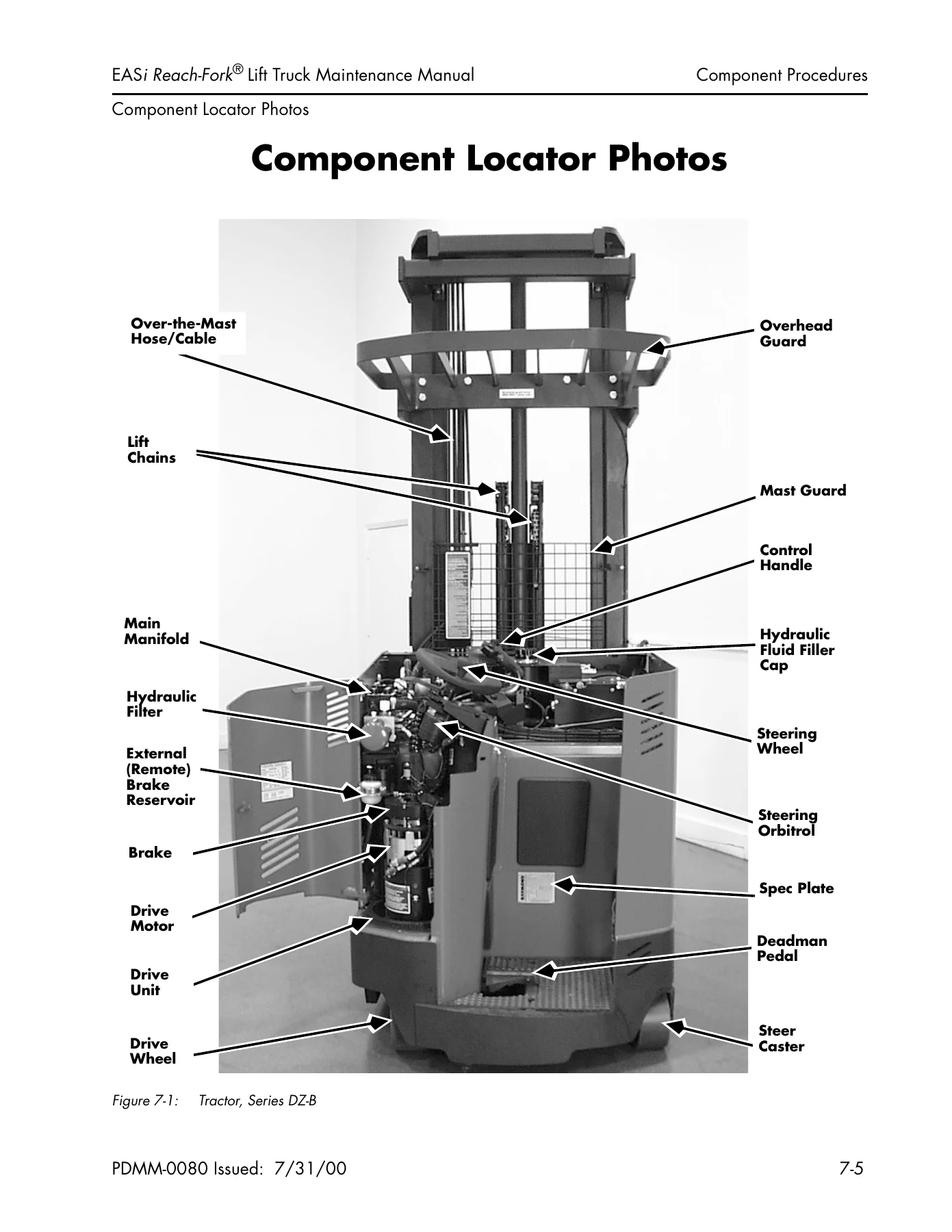
Component Locator Photosp. 271
Figure 7-1: Tractor, Series DZ-Bp. 271
Figure 7-2: Tractor, Series DZ-Bp. 272
Figure 7-3: Tractor, Series DZ-Ap. 273
Figure 7-4: Tractor, Series EZ-Ap. 274
Figure 7-5: Mast and Carriage, Series DZ-B Deep-Reach®p. 275
Figure 7-6: Underside Componentsp. 276
Covers and Finishp. 277
Right Side Coverp. 278
Figure 7-7: Right Side Cover, Series EZ-Bp. 278
Removalp. 278
Installationp. 278
Figure 7-8: Right Side Cover, Series DZ-Bp. 278
Top Coverp. 279
Series EZ, ES, ET, EFp. 279
Figure 7-9: Top Cover, Series EZ-B Cold Storage shownp. 279
Removalp. 279
Installationp. 279
Series DS, DT, DZp. 280
Figure 7-10: Top Cover, Series DZ-Bp. 280
Removalp. 280
Installationp. 280
OD/SMARTi® Coverp. 281
Series EZ, ES, ET, EFp. 281
Figure 7-11: OD/SMARTi® Cover, Series EZ-Bp. 281
Removalp. 281
Figure 7-12: Control Handle and OD Coverp. 281
Installationp. 281
Steering Wheel Coverp. 282
Series DS, DT, DZp. 282
Figure 7-13: Steering Wheel Cover, Series DZ-Bp. 282
Removalp. 282
Installationp. 282
Figure 7-14: Electronics Compartment Cover, Cold Storagep. 283
Electronics Compartment Coverp. 283
Removalp. 283
Figure 7-15: Electronics Compartment Cover, Cold Storage, Heatersp. 283
Installationp. 283
Drive Motor Compartment Doorp. 284
Figure 7-16: Drive Motor Compartment Doorp. 284
Openingp. 284
Removalp. 284
Installationp. 284
Decalsp. 285
Removalp. 285
Installationp. 285
Locationp. 285
Figure 7-17: Decal Location Chartp. 286
Figure 7-18: Decal and Specification Plate Locations, Tractorp. 287
Figure 7-19: Safety Decalsp. 288
Steering and Controlsp. 289
Steering Wheel and Knobp. 290
Series EZ, ES, ET, EFp. 290
Removalp. 290
Installationp. 290
Series DS, DT, DZp. 290
Removalp. 290
Installationp. 290
Steering Orbitrolp. 291
Figure 7-20: Steering Orbitrol (Series EZ-B shown)p. 291
Removalp. 291
Figure 7-21: Steering Orbitrol (Series DZ shown)p. 292
Installationp. 292
Steering Pumpp. 293
Steering Hydraulic Motorp. 293
Figure 7-22: Steering Hydraulic Motorp. 293
Removalp. 293
Installationp. 293
Steering Shaft and Gearp. 295
Figure 7-23: Steering Shaftp. 295
Removalp. 295
Figure 7-24: Steering Shaft and Gear Assemblyp. 296
Installationp. 296
Steering Electric Motor, Series EZ-B/DZ-B onlyp. 298
Figure 7-25: Steering Electric Motor Location (Series EZ-B Cold Storage shown)p. 298
Testingp. 298
Removalp. 298
Figure 7-26: Terminal Strip TS8 Locationp. 298
Figure 7-27: Hydraulic Filler Bracket, Attached Componentsp. 299
Installationp. 299
Figure 7-28: Steering Electric Motor, Impellerp. 300
Caster Assemblyp. 301
Removalp. 301
Installationp. 302
Steerable Casterp. 303
Figure 7-29: Setting Drive Wheel Parallelp. 303
Initial Adjustmentp. 303
Figure 7-30: Steering Adjustmentsp. 303
Figure 7-31: A-frame Down-Travel Adjustment Boltp. 304
Caster Height Adjustmentp. 304
Figure 7-32: A-frame Spring adjustmentsp. 304
Figure 7-33: A-frame Up-Travel Stop Adjustmentp. 306
Steering Linkagep. 307
Figure 7-34: Steering Linkagep. 307
Figure 7-35: Steering Linkage Exploded Viewp. 308
4-D® Casterp. 309
Figure 7-36: Connector JPS4 at System Cardp. 310
Control Handle, Series EZ/ES/ET/EFp. 310
Control Handle Shellp. 310
Removalp. 310
Figure 7-37: Control Handle Cable Retainer (EZ/ES/ET/EF)p. 310
Disassemblyp. 310
Figure 7-38: Control Handle Retaining Ring Removal (EZ/ES/ET/EF)p. 311
Figure 7-39: Control Handle, Right Halfp. 311
Figure 7-40: Control Handle Cable Routing (EZ,ES,ET,EF)p. 312
Assemblyp. 312
Figure 7-41: Tilt/Sideshift Button (EZ/ES/ET/EF)p. 312
Figure 7-42: Control Handle Assembly (EZ/ES/ET/EF)p. 312
Figure 7-43: Control Handle Installation (EZ/ES/ET/EF)p. 313
Installationp. 313
Figure 7-44: Control Handle Cable Loop (EZ/ES/ET/EF)p. 313
Throttle Potentiometer (VR1)p. 314
Removalp. 314
Figure 7-45: Throttle Potentiometer VR1 (EZ/ES/ET/EF)p. 314
Installationp. 315
Lift/Lower Potentiometer (VR2)p. 316
Figure 7-46: Lift Lower Potentiometer VR2 (EZ/ES/ET/EF)p. 316
Return Spring Replacementp. 316
Lift Knob Replacement, solid state pots onlyp. 317
Potentiometer Removalp. 317
Potentiometer Installationp. 318
Figure 7-47: Lift/Lower Knob and Potentiometer (EZ/ES/ET/EF)p. 318
Tilt/Sideshift Switch Card (S6-S9)p. 319
Figure 7-48: Tilt/Sideshift Switch Card (EZ/ES/ET/EF cold storage)p. 320
Removal (Cold Storage)p. 320
Installationp. 320
Horn Switch (S3)p. 321
Reach/Retract Switches (S4/S5)p. 321
Figure 7-49: Horn and Reach/Retract Switches (EZ/ES/ET/EF)p. 321
Removalp. 321
Installationp. 321
Figure 7-50: Connector JPS4 at System Cardp. 323
Control Handle, Series DS/DT/DZp. 323
Control Handle Shellp. 323
Removalp. 323
Disassemblyp. 323
Figure 7-51: Control Handle, Right Half (DS/DT/DZ)p. 324
Figure 7-52: Control Handle Cable Routing (DS/DT/DZ)p. 324
Assemblyp. 324
Figure 7-53: Tilt/Sideshift Button (DZ/DS/DT)p. 324
Figure 7-54: Control Handle Assembly (DS/DT/DZ)p. 325
Figure 7-55: Lift/Lower Knob and Potentiometer (DS/DT/DZ)p. 325
Figure 7-56: Control Handle Installation (DS/DT/DZ)p. 325
Installationp. 325
Figure 7-57: Control Handle Cable Loop (DS/DT/DZ)p. 326
Figure 7-58: Throttle Potentiometer VR1 (DS/DT/DZ)p. 326
Throttle Potentiometer (VR1)p. 326
Removalp. 326
Installationp. 327
Figure 7-59: Control Handle Shaft Installation (DS/DT/DZ)p. 328
Lift/Lower Potentiometer (VR2)p. 329
Return Spring Replacementp. 329
Figure 7-60: Lift Power Potentiometer VR2 (DS/DT/DZ)p. 329
Lift Knob Replacement, solid state pots onlyp. 329
Potentiometer Removalp. 330
Potentiometer Installationp. 330
Tilt/Sideshift Switch Card (S6-S9)p. 331
Figure 7-61: Tilt/Sideshift Switch Card (DS/DT/DZ cold storage)p. 332
Removal (Cold Storage)p. 332
Installationp. 332
Figure 7-62: Horn and Reach/Retract Switches (DS/DT/DZ)p. 333
Horn Switch (S3)p. 333
Reach/Retract Switches (S4/S5)p. 333
Removalp. 333
Installationp. 333
Key Switchp. 335
Electrostatic Dischargep. 335
Figure 7-63: Key Switch (Series EZ/ES/ET/EF)p. 335
Removalp. 335
Figure 7-64: Key Switch (Series DS/DT/DZ)p. 335
Installationp. 335
Operator Display (OD)p. 336
Pre-programmed vs. blank ODp. 336
Electrostatic Dischargep. 336
Figure 7-65: Operator Display Interface Cardp. 337
Removalp. 337
Figure 7-66: Operator Display Interface Cardp. 337
Installationp. 337
4-D® Control Panel and Displayp. 339
Figure 7-67: 4-D Control Panelp. 339
Removalp. 339
Installationp. 339
Drive and Brakep. 341
Drive Unitp. 342
Figure 7-68: Drive Unit Removal/Installation Toolp. 342
Removalp. 342
Figure 7-69: Drive Motor, Series EZ-Bp. 343
Installationp. 344
Repair Proceduresp. 345
Figure 7-70: Drive Motor Power Cablesp. 346
Drive Motorp. 346
Removalp. 346
Figure 7-71: Drive Motor, Series EZ-Bp. 346
Figure 7-72: Securing Hoist to Drive Motorp. 347
Installationp. 347
Drive Encoderp. 350
Figure 7-73: Drive Encoderp. 350
Removalp. 350
Figure 7-74: Drive Encoder Connection at System Card JPS15p. 350
Installationp. 350
Brake Adjustmentp. 352
Figure 7-75: Brake Assembly, Snap Ring Stylep. 352
Snap Ring Style Brakep. 352
Figure 7-76: Brake Assembly, Nut-Retained Stylep. 355
Nut-Retained Style Brakep. 355
Without Adjusting Boltsp. 355
With Adjusting Boltsp. 356
Figure 7-77: Brake Adjusting Bolt detailp. 356
Brake Pad Inspectionp. 358
Bleeding Brakep. 358
Brake Assemblyp. 359
Snap Ring Style Brakep. 359
Removalp. 359
Disassemblyp. 360
Assemblyp. 360
Installationp. 360
Brake O-ring Seal Replacementp. 362
Deadman (Brake) Pedalp. 365
Inspectionp. 365
Adjustmentp. 365
Figure 7-78: Deadman Switch (Series EZ/ES/ET/EF)p. 367
Deadman Switch (S2)p. 367
Removalp. 367
Figure 7-79: Deadman Switch (Series EZ/ES/ET/EF)p. 367
Installation and Adjustmentp. 367
Figure 7-80: Deadman Switch and Bracketp. 368
Figure 7-81: Deadman Switch (Series DS/DT/DZ)p. 368
Figure 7-82: Deadman Pedal, Switch, and Master Cylinder Assembly (DS/DT/DZ)p. 369
Brake Master Cylinderp. 369
Removalp. 369
Figure 7-83: Deadman Switch (DS/DT/DZ)p. 369
Figure 7-84: Brake Master Cylinder and Deadman Pedalp. 370
Installation and Bleedingp. 370
Inertial Dampenerp. 372
Figure 7-85: Inertial Dampener (unrelated parts removed for clarity)p. 372
Removalp. 372
Figure 7-86: Inertial Dampener (nuts, retainer, springs, friction plate removed)p. 372
Figure 7-87: Inertial Dampener (A-frame springs, slide plate removed)p. 373
Figure 7-88: Inertial Dampener (jacked up for shoulder bolt removal)p. 373
Installation and Adjustmentp. 373
Figure 7-89: Inertial Dampener partsp. 374
Figure 7-90: Inertial Dampener adjustmentp. 374
Electrical Componentsp. 375
Figure 7-91: Battery Disconnect Blockp. 376
Battery Proceduresp. 376
Battery Connector/Cablesp. 376
Locationp. 376
Inspectionp. 376
Figure 7-92: Battery Cable Removal from Connectorp. 377
Removal, Repair, and Installationp. 377
Figure 7-93: Battery Cable and Connectorp. 377
Battery Gatesp. 377
Inspectionp. 377
Battery Rollersp. 378
Inspectionp. 378
Figure 7-94: Battery Cable and Filler Plugp. 378
Battery Exterior Cleaningp. 378
Testing, Charging, and Maintenancep. 379
Battery State-of-Chargep. 379
Figure 7-95: Chip Extraction tool P/N 950-032p. 382
Firmware Replacementp. 382
General Instructionsp. 382
Figure 7-96: Firmware Socket and Chipp. 382
Removalp. 382
Figure 7-97: Firmware Chip Removalp. 382
Figure 7-98: Firmware Chip Inspection (chips upside down to reveal pins)p. 383
Chip Installationp. 383
Figure 7-99: Firmware Chip improperly seated in socketp. 383
Figure 7-100: Firmware Chip fully seated in socketp. 383
Pin Extractionp. 384
Figure 7-101: Molex Connector, end viewp. 384
Removalp. 384
Insertionp. 384
Figure 7-102: Pin Extractionp. 384
Wiring, Generalp. 385
Inspectionp. 385
Repairp. 385
Soldering Proceduresp. 386
Motorsp. 387
Figure 7-103: Motor Brush, Typical Locationp. 387
Motor Brushesp. 387
Inspectionp. 387
Replacementp. 388
Motor Brush Spring Tensionp. 389
Figure 7-104: Motor Brush Spring Tension Inspectionp. 389
Inspectionp. 389
Commutatorp. 392
Figure 7-105: Mica Undercuttingp. 392
Inspectionp. 392
Servicingp. 392
Figure 7-106: Motor Terminal Nutsp. 393
Terminal Nutsp. 393
Electric Motor Testsp. 394
Figure 7-107: Motor Circuitsp. 394
Motor Typesp. 394
Open Circuit Motor Testp. 394
Grounded Motor Testp. 395
Short Circuited Armature or Field Windingp. 396
Drive Motorp. 398
Electric Steering Motorp. 398
Lift Motorp. 399
Figure 7-108: Lift Motor, Series DZ-Ap. 399
Lift Motor – Series EZ-A/ES/ET/EF/DZ-A/DS/DTp. 399
Testingp. 399
Removalp. 399
Figure 7-109: Lift Motor Fan, Series EZ-Ap. 400
Installationp. 400
Lift Motor – Series EZ-B/DZ-Bp. 402
Figure 7-110: Control Handle Removalp. 402
Testingp. 402
Figure 7-111: Terminal Strip TS8 Location, Series EZ-Bp. 402
Removalp. 402
Figure 7-112: Hydraulic Filler Bracket, Attached Componentsp. 403
Figure 7-113: Lift Motor/Pump and Steering Motor/Pumpp. 403
Figure 7-114: Lift Pump, Accessing Lower Mounting Boltp. 403
Figure 7-115: Lift Motor Temperature Sensor and Connectorp. 404
Figure 7-116: Hydraulic Filler Bracket, Attached Componentsp. 404
Installationp. 404
Auxiliary Motorp. 407
Figure 7-117: Aux Motor, Series DZ-Ap. 407
Auxiliary Motor, Series ES/ET/EZ-A/DS/DT/DZ-Ap. 407
Testingp. 407
Removalp. 407
Figure 7-118: Aux Motor, Series EZ-Ap. 407
Installationp. 408
Figure 7-119: Auxiliary Pump and Motor Couplingp. 408
Auxiliary Motor, Series EZ-B/DZ-Bp. 409
Figure 7-120: Auxiliary Motor, Series EZ-Bp. 409
Testingp. 409
Removalp. 409
Figure 7-121: Auxiliary Pump and Motor Couplingp. 410
Installationp. 410
Contactorsp. 411
Figure 7-122: Contactor location, 3-motor, non-cold storagep. 411
Contactor Removalp. 411
Contactor Installationp. 411
Figure 7-123: Contactor location, 4-motor, cold storagep. 411
Figure 7-124: Contactor / Fuse Panel Layout, 4-motor, Non-Cold Storagep. 412
Figure 7-125: Contactor / Fuse Panel Layout, 4-motor, Cold Storagep. 412
Figure 7-126: Contactor / Fuse Panel Layout, 3-motor, Non-Cold Storagep. 413
Figure 7-127: Contactor / Fuse Panel Layout, 3-motor, Cold-Storagep. 413
Contactor Tip Replacementp. 414
Inspectionp. 414
Figure 7-128: Severely Pitted Contactor Tipsp. 414
Figure 7-129: Contactorp. 414
Contactor Tip Kitp. 414
Removalp. 415
Figure 7-130: Contactorp. 415
Figure 7-131: Contactorp. 415
Replacementp. 415
Figure 7-132: Contactorp. 416
Figure 7-133: Power Panel Temperature Sensorp. 417
Temperature Sensorp. 417
Removalp. 417
Figure 7-134: Drive Motor Temperature Sensorp. 417
Figure 7-135: Lift Motor Temperature Sensor, EZ-B/DZ-Bp. 417
Installationp. 417
Figure 7-136: Lift Motor Temperature Sensor, DZ-Ap. 418
Fusesp. 419
Test/Inspectionp. 419
Fuse Locator Chartp. 419
Figure 7-137: Mechanical Horn and Suppressor, Series ETp. 421
Horn Componentsp. 421
Horn and Suppressor Removalp. 421
Figure 7-138: Mechanical Horn and Suppressor, Series DZp. 421
Horn and Suppressor Installationp. 421
Figure 7-139: Electronic Horn and Suppressor, Series EZp. 422
Horn Suppressor Module Retrofitp. 422
Horn Relay (K2) Removalp. 423
Figure 7-140: Horn Relay location on system cardp. 423
Horn Relay (K2) Installationp. 423
Static Strapp. 424
Figure 7-141: Static Strap location on undersidep. 424
Inspection, Removal, Installationp. 424
Cold Storage Componentsp. 425
Figure 7-142: Control Panel Cover Heaters and Thermostatsp. 425
Control Panel & Control Panel Cover Heaters and Thermostatsp. 425
Removalp. 425
Figure 7-143: Control Panel Heater and Thermostatsp. 425
Installationp. 425
Control Handle Heaterp. 426
Figure 7-144: Cold Storage Heater Fuse locationsp. 426
Power Panel (Traction) Heatsinkp. 427
Removalp. 427
Figure 7-145: Power Panel (Traction) Heatsink locationp. 427
Installationp. 428
Figure 7-146: Power Panel (Traction) Heatsink componentsp. 428
Power Transistor (Q1)p. 429
Figure 7-147: Main Power Transistor Q1 on Power Panelp. 429
Removalp. 429
Installationp. 429
Testingp. 430
Figure 7-148: Q1 Power Transistor Connectionsp. 430
Figure 7-149: Regen Assembly locationp. 432
Regen Assemblyp. 432
Removalp. 432
Installationp. 432
Rectifiersp. 434
REC1, REC2, REC3p. 434
Figure 7-150: REC1, REC2, and REC3p. 434
Removalp. 434
Installationp. 434
Testingp. 435
Snubber Resistor R2p. 437
Figure 7-151: Snubber Resistor R2 location on Power Panelp. 437
Testingp. 437
Figure 7-152: System Card Componentsp. 438
System Cardp. 438
Removalp. 438
Installationp. 439
VFC Cardp. 441
Removalp. 441
Figure 7-153: VFC Card Location on System Cardp. 441
Figure 7-154: VFC Card, Removedp. 442
Installationp. 442
Figure 7-155: Power Card Locationp. 443
Power Cardp. 443
Removalp. 443
Figure 7-156: Power Card Connectionsp. 443
Installationp. 444
Coil Driver Cardsp. 445
Removalp. 445
Figure 7-157: Coil Driver Boardsp. 445
Installationp. 445
Figure 7-158: 4-D Circuit Cardp. 446
4-D® Circuit Cardp. 446
Removalp. 446
Figure 7-159: 4-D Circuit Card Connectorsp. 446
Installationp. 446
Field Transistors TM1/TM2p. 448
Removalp. 448
Installationp. 448
Testing TM1/TM2p. 449
Figure 7-160: TM1/TM2 Field Transistor Connectionsp. 449
SMARTi® Modulep. 450
Removalp. 450
Installationp. 450
Operationp. 450
Line Filterp. 451
Figure 7-161: Line Filter, Series EZ-Bp. 451
Removalp. 451
Figure 7-162: Line Filter, Series DZ-Bp. 451
Installationp. 451
Figure 7-163: 4-D Caster Switch detailp. 452
Switch S61/S62 (4-D®Caster Wheel)p. 452
Removalp. 452
Figure 7-164: 4-D Caster Switches and Bracketp. 452
Replacementp. 452
4-D® Proximity Sensorp. 454
Figure 7-165: 4-D Proximity Sensor relative to Drive Motorp. 454
Removalp. 454
Figure 7-166: PS63 connection on 4-D Circuit Cardp. 454
Installation and Adjustmentp. 455
Figure 7-167: 4-D Proximity Sensor alignmentp. 456
Figure 7-168: 4-D Proximity Sensor and Harnessp. 456
4-D® Proximity Sensor Sensing Ringp. 457
Figure 7-169: 4-D Proximity Sensor Sensing Ring at Drive Motorp. 457
Removalp. 457
Figure 7-170: 4-D Proximity Sensor Sensing Ringp. 457
Replacementp. 457
Hydraulic Componentsp. 459
Hydraulic Fluid Replacementp. 460
Series EZ-Bp. 460
Draining the Systemp. 460
Figure 7-171: Auxiliary Motor Pressure Line at Manifoldp. 460
Refilling the Systemp. 461
Bleeding the Systemp. 462
Procedurep. 462
Figure 7-172: Bleed Screw, Side Lift Cylinderp. 462
Lift Pumpp. 464
Lift Pump – Series EZ-B/DZ-Bp. 464
Figure 7-173: Lift Pump Location, Series EZ-Bp. 464
Removalp. 464
Figure 7-174: Lift Pump, Series EZ-Bp. 464
Installationp. 465
Figure 7-175: Lift Pump, Accessing Lower Mounting Boltp. 465
Lift Pressure Adjustmentp. 466
Figure 7-176: Lift Pressure Test Port, Series EZ-B/DZ-Bp. 466
Figure 7-177: Lift Pressure Test Port, Series EZ-A/ES/ET/EF/DZ-A/DS/DTp. 466
Figure 7-178: Lift Pressure Relief Valve & Adjusting Screw, Series EZ-B/DZ-Bp. 467
Figure 7-179: Lift Pressure Relief Valve & Adjusting Screw, Series EZ-A/ES/ET/EF/DZ-A/DS/DTp. 467
Auxiliary Pumpp. 468
Aux Pump – Series EZ-B/DZ-Bp. 468
Figure 7-180: Auxiliary Pump, Series EZ-Bp. 468
Removalp. 468
Figure 7-181: Auxiliary Pump with Couplingp. 469
Installationp. 469
Figure 7-182: Auxiliary Pressure Adjustment Port, Series EZ-B/DZ-Bp. 470
Auxiliary System Pressure Adjustmentp. 470
Figure 7-183: Auxiliary Pressure Adjustment Port, Series DZ-A shownp. 470
Figure 7-184: Aux Pressure Adjustment Screw, Series EZ-Bp. 471
Steering Pumpp. 472
Figure 7-185: Control Handle Removalp. 472
Steering Pump – Series EZ-B/DZ-B Onlyp. 472
Removalp. 472
Figure 7-186: Steering Pumpp. 472
Figure 7-187: Steering Pump with Couplingp. 473
Installationp. 473
Steering Pressure Adjustmentp. 474
Figure 7-188: Steering Pressure Adjustment Portp. 474
Series EZ-B/DZ-B Onlyp. 474
Figure 7-189: Steering Pressure Test Port, Series EZ-Bp. 474
Manifold, Mainp. 476
Figure 7-190: Manifold Layout, Series EZ-A/ES/ET/EF/DS/DT, Top View (Dual Lift Pump shown)p. 476
Figure 7-191: Manifold Layout, Series EZ-A/ES/ET/EF/DS/DT, Side View (Dual Lift Pump shown)p. 476
Figure 7-192: Main Manifold, Single Pumpp. 477
Main Manifold – Series EZ-A/ES/ET/DS/DTp. 477
Removalp. 477
Figure 7-193: Main Manifold, Dual Pumpp. 477
Installationp. 478
Main Manifold – Series EZ-B/DZ-Bp. 480
Figure 7-194: Manifold Layout, Series EZ-B/DZ-B, Top Viewp. 480
Figure 7-195: Manifold Layout, Series EZ-B/DZ-B, Side Viewp. 480
Figure 7-196: Hydraulic Manifold, Series EZ-Bp. 481
Removalp. 481
Figure 7-197: Lift Pump and Pressure Hosesp. 482
Figure 7-198: Solenoid, Typical, Coil Removedp. 482
Installationp. 482
Manifold, Reachp. 484
Figure 7-199: Reach Manifoldp. 484
Removalp. 484
Installationp. 484
Manifold, Tilt/Sideshiftp. 485
Figure 7-200: Tilt/Sideshift Manifold Tractor Side (Tilt Manifold Shown)p. 485
Removalp. 485
Figure 7-201: Tilt/Sideshift Manifold Forks Sidep. 485
Installationp. 485
Solenoids (General)p. 486
Figure 7-202: Solenoid Removal, Typicalp. 486
Removalp. 486
Installationp. 486
Figure 7-203: Solenoid Valve and Coil, Typicalp. 486
Hydraulic Solenoidp. 487
Solenoid – Series EZ-Bp. 487
Figure 7-204: Solenoid, Typical, Coil Removedp. 487
Removalp. 487
Installationp. 488
Hydraulic Componentsp. 489
Adjustment (Proportional Valve)p. 489
Hydraulic Componentsp. 491
Solenoid, 4-D Caster Wheel Positionerp. 491
Figure 7-205: 4-D Wheel Positioner Solenoidp. 491
Removalp. 491
Figure 7-206: 4-D Caster Wheel Positioner Solenoid Locationp. 491
Replacementp. 492
Pressure Transducerp. 493
Diagnosing Failuresp. 493
Figure 7-207: Connector PS-6 at System Cardp. 494
Figure 7-208: Pressure Transducer, Series EZ-Bp. 494
Removalp. 494
Figure 7-209: Pressure Transducer, Series EZ-Ap. 495
Installationp. 495
Pressure Switch, HTIp. 496
Hydraulic Componentsp. 497
Lift Cylindersp. 497
Figure 7-210: Lift Cylinder, Back Cylinder, exploded viewp. 498
Figure 7-211: Lift Cylinder, Front Cluster, exploded view (Part 1 of 2)p. 499
Figure 7-212: Lift Cylinder, Front Cluster, exploded view (Part 2 of 2)p. 500
Lift Cylinder, Front Clusterp. 501
Removalp. 501
Installationp. 502
Lift Cylinder, Back Cylinder, Threaded Anchor Retentionp. 504
Figure 7-213: Reach carriage removedp. 504
Removalp. 504
Installationp. 505
Figure 7-214: Anchoring lift cylinderp. 505
Figure 7-215: Blocking telescopicsp. 506
Adjustmentp. 506
Figure 7-216: Checking pivot support platep. 506
Figure 7-217: Blocking inner telescopicp. 507
Lift Cylinder, Back Cylinder, Spiral Ring Retentionp. 508
Spiral Ring Inspectionp. 508
Hydraulic Componentsp. 509
Lift Cylinder, Back Cylinder, Spiral Ring Retentionp. 509
Figure 7-218: Spiral Ring, Windingp. 509
Figure 7-219: Spiral Ring, Seatedp. 509
Cylinder Removalp. 512
Lift Cylinder, Back Cylinder, Spiral Ring Retentionp. 513
Cylinder Installationp. 513
Lift Cylinder, Side Cylinder Seal Repackingp. 516
Removalp. 516
Repacking and Assemblyp. 517
Figure 7-220: Cylinder Seal Installation Guide & Driverp. 517
Lift Cylinder Front and Back Cylinder Seal Repackingp. 519
Removalp. 519
Repacking and Assemblyp. 520
Figure 7-221: Cylinder Seal Installation Guide & Driverp. 520
Lift Cylinder Lowering Cushionp. 521
Removalp. 521
Installationp. 522
Flow Controlp. 523
Removalp. 523
Figure 7-222: Flow Control, Blockingp. 523
Installationp. 524
Reach Cylinderp. 525
Adjustmentp. 525
Figure 7-223: Blocking Carriagep. 525
Removalp. 525
Figure 7-224: Reach Cylinder Hydraulic Hosesp. 525
Figure 7-225: Reach Cylinder Yoke Attachmentp. 526
Figure 7-226: Reach Cylinder Housing Attachmentp. 526
Disassemblyp. 526
Figure 7-227: Removing External Lock Ringp. 526
Figure 7-228: Reach Cylinder Disassemblyp. 527
Reassemblyp. 527
Figure 7-229: Deep-Reach® Cylinder Disassemblyp. 528
Installationp. 529
Figure 7-230: Blocking the Reach Carriagep. 530
Tilt Cylinderp. 530
Removalp. 530
Figure 7-231: Tilt Cylinder Hoses and Yokesp. 530
Figure 7-232: Tilt Cylinder Snap Ringp. 530
Figure 7-233: Tilt Cylinder Piston and Connecting Pinp. 531
Installationp. 531
Figure 7-234: Tilt Cylinder, Disassemblyp. 532
Disassemblyp. 532
Reassemblyp. 532
Sideshift Cylinderp. 534
Cascade Sideshift Cylinderp. 534
Removalp. 534
Figure 7-235: Cascade Sideshift Cylinderp. 534
Installationp. 534
Figure 7-236: Sideshift Cylinder, Clampedp. 535
Disassemblyp. 535
Figure 7-237: Sideshift Cylinder Retaining Ring Removalp. 535
Figure 7-238: Sideshift Cylinder, Piston Removalp. 536
Figure 7-239: Sideshift Cylinder, Seal Removalp. 536
Figure 7-240: Sideshift Cylinder, Cross Sectionp. 537
Reassemblyp. 537
Bolzoni Sideshift Cylinderp. 538
Removalp. 538
Installationp. 538
Disassembly/Reassemblyp. 539
Figure 7-241: Bolzoni Sideshift Assemblyp. 540
4-D® Caster Wheel Positioner Cylinderp. 541
Figure 7-242: 4-D Caster Positioner Cylinderp. 541
Removalp. 541
Replacementp. 542
Mast, Chain, Hose and Cablep. 543
Mast Typesp. 544
Figure 7-243: Blocking Inner and Outer Telescopicsp. 545
Over-the-Mast Hose/Cablep. 545
Removalp. 545
Figure 7-244: Blocking Reach Carriagep. 545
Figure 7-245: Over-the-Mast Hose/Cable Retaining Screwsp. 545
Figure 7-246: Over-the-Mast Hose connections (reach)p. 546
Installationp. 546
Adjustmentp. 547
Figure 7-247: Hose and Cable Tension Adjustmentp. 547
Mast Bearing Shimmingp. 549
Generalp. 549
Figure 7-248: Blocking Mastp. 549
Main Mast Upper Bearing Shimmingp. 549
Figure 7-249: Upper Mast Bearing, Outer Telescopicp. 550
Figure 7-250: Upper Mast Bearing, Main Mastp. 551
Complete Mast Shimmingp. 551
Objective of Mast Shimmingp. 551
This section describes procedures for:p. 552
Mast Disassemblyp. 552
Figure 7-251: Mast Disassembly, securing hoses/cablep. 552
Shimming Main Frame to Outer Telescopicp. 553
Figure 7-252: Shimming Outer Telescopic Bearingp. 553
Shimming Outer Telescopic to Inner Telescopicp. 555
Figure 7-253: Shimming Inner Telescopic Bearingp. 555
Shimming Inner Telescopic to Carriagep. 557
Bearings, Reach Carriagep. 560
Figure 7-254: Reach Carriage Roller Bearingsp. 560
Removalp. 560
Installationp. 560
Bearings, Reach Half Shaftp. 561
Figure 7-255: Half Shaft Locationp. 561
Removalp. 561
Figure 7-256: Half Shaft Assemblyp. 561
Installationp. 561
Reach Carriage Assemblyp. 563
Figure 7-257: Blocking Reach Mechanism and Forksp. 563
Removalp. 563
Figure 7-258: Carriage Removal, Hoses, Cable, and Chainsp. 563
Figure 7-259: Carriage Removedp. 564
Installationp. 565
Reach Carriage Bumpersp. 567
Removalp. 567
Figure 7-260: Blocking Reach Mechanismp. 567
Figure 7-261: Reach Wear Stripp. 567
Installationp. 567
Reach Carriage Wear Stripsp. 568
Removalp. 568
Figure 7-262: Blocking Reach Mechanismp. 568
Figure 7-263: Reach Wear Stripp. 568
Installationp. 568
Forksp. 569
Figure 7-264: Fork Latchp. 569
Fork Position Adjustmentp. 569
Figure 7-265: Fork Wear Calipersp. 569
Fork Tip Height Adjustmentp. 569
Fork Inspectionp. 569
Figure 7-266: Fork Wear Inspectionp. 570
Figure 7-267: Fork Latch and Safety Boltp. 570
Removal (with Tilt and Sideshift)p. 570
Figure 7-268: Fork Removal (with Tilt and Sideshift)p. 570
Installation (with Tilt and Sideshift)p. 570
Figure 7-269: Fork Removal (with Tilt and no Sideshift)p. 571
Removal (with Tilt and no Sideshift)p. 571
Installation (with Tilt and no Sideshift)p. 571
Lift Chains, Mainp. 572
Generalp. 572
Adjustmentp. 572
Lubricationp. 573
Figure 7-270: Chain Anchor Nut lubricationp. 573
Defect-Cause Chartp. 574
Removalp. 575
Figure 7-271: Blocking Carriagep. 575
Installationp. 576
Reach Carriage Lift Chain Anchorsp. 578
Upper (Adjustable) Chain Anchorp. 578
Removalp. 578
Installationp. 578
Lower Chain Anchorsp. 579
Removalp. 579
Installationp. 579
Equalization Chainsp. 581
Adjustmentp. 581
Figure 7-272: Equalization Chain Adjustmentp. 581
Lubricationp. 582
Removalp. 583
Figure 7-273: Blocking Inner and Outer Telescopicsp. 583
Figure 7-274: Equalization Chain Adjuster Locknutp. 583
Figure 7-275: Equalization Chain Anchor Cap Screwsp. 584
Installationp. 584
Figure 7-276: Equalization Chain Sheave Access Plate (7/8 Inch or 18/20 cm mast)p. 585
Equalization Chain Sheavep. 585
7- or 8-Inch (18- or 20-cm) Deep Mast Uprightsp. 585
Removalp. 585
Figure 7-277: Equalization Chain Anchor Locknutp. 585
Figure 7-278: Equalization Chain Anchor Cap Screwsp. 586
Installationp. 586
9-Inch (23-cm) Deep Mast Uprightsp. 586
Removalp. 586
Installationp. 586
Carriage Bumpersp. 587
Removalp. 587
Installationp. 587
Mechanical Stops Adjustmentp. 588
Figure 7-279: Mast Bumper Adjustmentp. 588
Figure 7-280: Mast Stop Adjustmentp. 588
Fork Carriage Tilt Pinsp. 589
Removalp. 589
Figure 7-281: Fork Carriage Tilt Pinp. 589
Figure 7-282: Removing Tilt Pivot Pinp. 589
Installationp. 589
Figure 7-283: Baseleg undersidep. 590
4-D Caster: Wheels, Wheel Bearings, Thrust Bearing, Swivel Bearingp. 590
Figure 7-284: 4-D Caster and Cylinderp. 590
Disassemblyp. 590
Figure 7-285: 4-D Caster Wheel and Bearingsp. 592
Figure 7-286: 4-D Caster disassembledp. 592
Reassemblyp. 593
Mast Backlash Adjustmentp. 595
Adjustmentp. 595
Figure 7-287: Mast Backlash Bolt locationp. 595
Optionsp. 597
Cold Storage Requirementsp. 598
Componentsp. 598
Requiredp. 598
Not Permittedp. 598
Lubricantsp. 598
Sealing Treatmentp. 598
Corrosion Inhibitor Coatingp. 599
Fork Height-Tilt Indicator (HTI)p. 600
Fork Height Indicatorp. 600
Fork Tilt Indicatorp. 600
HTI Codes and Troubleshootingp. 601
Code E1p. 601
Code E2p. 602
HTI Active Maintenance Modep. 603
Figure 7-288: HTI Displayp. 603
Figure 7-289: HTI Active Maintenance Mode segmentsp. 604
Component Proceduresp. 605
Mast Locationsp. 605
Figure 7-290: Typical left side mast location (drawing shows view from forks toward mast)p. 606
Figure 7-291: Typical right side mast location (drawing shows view from forks toward mast)p. 607
Fork Height Indicatorp. 608
Cable Replacementp. 608
Figure 7-292: HTI Cable attachment (top)p. 608
Removalp. 608
Figure 7-293: HTI Cable attachment (bottom)p. 608
Installationp. 608
Figure 7-294: HTI Encoder Cable Pathp. 609
HTI Encoder Assemblyp. 610
Figure 7-295: HTI Encoder Assembly Installationp. 610
Removalp. 610
Installationp. 610
Figure 7-296: HTI Encoder Assemblyp. 610
HTI Display Cardp. 611
Figure 7-297: HTI Display Cardp. 611
Removalp. 611
Figure 7-298: HTI Display locationp. 612
Installationp. 612
Figure 7-299: HTI Display Cardp. 612
Calibrating and Setting the Height Indicatorp. 612
Figure 7-300: HTI Displayp. 613
Fork Tilt Indicatorp. 614
Fork Carriage Shimmingp. 614
Figure 7-301: Tilt Plates and Shims (one side visible)p. 614
HTI Pressure Switch (S31)p. 615
Figure 7-302: Pressure Switch location, 4-motor lift trucksp. 615
Removalp. 615
Figure 7-303: Pressure Switch location, 3-motor lift trucksp. 615
Installationp. 615
Adjustmentp. 616
Figure 7-304: Tilt Pressure Switchp. 616
HTI Theory of Operationp. 616
Fork Height Indicatorp. 616
Fork Tilt Indicatorp. 617
Electrical Schematicp. 618
Figure 7-305: HTI Electrical Schematicp. 618
Theory of Operationp. 619
Traction System Functional Operationp. 620
Overviewp. 620
Power Transistor Descriptionp. 620
Figure 8-1: Power Transistor Operationp. 620
Operation of the Travel Systemp. 621
Connecting Battery, Three-Motor Configurationp. 621
Figure 8-2: Connecting the Battery – Three-Motor (Sheet 1 of 2)p. 622
Figure 8-3: Connecting the Battery – Three-Motor (Sheet 2 of 2)p. 623
Connecting Battery, Four-Motor Configurationp. 624
Figure 8-4: Connecting the Battery – Four-Motor (Sheet 1 of 2)p. 625
Figure 8-5: Connecting the Battery – Four-Motor (Sheet 2 of 2)p. 626
Turning Key Switch (S1) ON, Three-Motor Configurationp. 627
Three-Motor Configurationp. 627
Figure 8-6: Turning the Key Switch (S1) ON – Three-Motor (Sheet 1 of 2)p. 628
Figure 8-7: Turning the Key Switch (S1) ON – Three-Motor (Sheet 2 of 2)p. 629
Turning Key Switch (S1) ON, Four-Motor Configurationp. 630
Four-Motor Configurationp. 630
Figure 8-8: Turning the Key Switch (S1) ON – Four-Motor (Sheet 1 of 2)p. 631
Figure 8-9: Turning the Key Switch (S1) ON – Four-Motor (Sheet 2 of 2)p. 632
Startup Sequencep. 633
SelfTest Checksp. 633
Closing Deadman Switch (S2)p. 634
Figure 8-10: Closing Deadman Switch (S2) – Three-Motor (Sheet 1 of 2)p. 635
Figure 8-11: Closing Deadman Switch (S2) – Three Motor (Sheet 2 of 2)p. 636
Requesting Travelp. 637
Figure 8-12: Drive Motor Encoder Phasesp. 638
Figure 8-13: Requesting Forward Travel – Three-Motor (Sheet 1 of 2)p. 639
Figure 8-14: Requesting Forward Travel – Three-Motor (Sheet 2 of 2)p. 640
Contactor Coilsp. 641
Figure 8-15: 24 Volt Contactor Coil Voltage Readingsp. 641
Closed Loop Speed Controlp. 642
Figure 8-16: Closed Loop Speed Control Functional Block Diagramp. 642
Torque On Demandp. 643
Figure 8-17: Torque On Demandp. 643
Thermal Cut-Backp. 644
Elevated Height Limitsp. 644
Current Limitingp. 645
Figure 8-18: Duty Cycle Comparison for Current Limitingp. 645
Requesting Travel: B Speedp. 646
Figure 8-19: “B” Speed (Bypass) Operation – Three-Motor (Sheet 1 of 2)p. 647
Figure 8-20: “B” Speed (Bypass) Operation – Three-Motor (Sheet 2 of 2)p. 648
Proportional Pluggingp. 650
Figure 8-21: Recirculation and Proportional Pluggingp. 651
Regenerative Brakingp. 652
Regenp. 652
Figure 8-22: Regenerative Braking – Q1 turned OFFp. 653
Figure 8-23: Regenerative Braking – Q2 turned ONp. 655
Drive Modep. 656
Figure 8-24: Regenerative Braking – Drive Modep. 657
Brake Systemp. 658
Braking Processp. 658
Steering Systemp. 660
Three-Motor Configurationp. 660
Figure 8-25: Hydraulic Schematic – Steering Theory, 3-motorp. 661
Four-Motor Configurationp. 662
Figure 8-26: Hydraulic Schematic – Steering Theory, 4-motorp. 663
Lift/Lower System Functional Operationp. 664
Liftp. 664
Variable Liftp. 664
Figure 8-27: Pulse Width Modulation duty cyclep. 664
Figure 8-28: Variable Lift – Hydraulicp. 665
Figure 8-29: Lift – System Card (Sheet 1 of 2)p. 666
Figure 8-30: Lift – System Card (Sheet 2 of 2)p. 667
High-Speed Lift (lift trucks with dual lift pump)p. 668
Figure 8-31: High Speed Lift – Hydraulicp. 669
Lowerp. 670
Figure 8-32: Pulse Width Modulation duty cyclep. 670
Figure 8-33: Variable Lower – Hydraulicp. 671
Figure 8-34: Lower – Three-Motor (Sheet 1 of 2)p. 672
Figure 8-35: Lower – Three-Motor (Sheet 2 of 2)p. 673
Remote Lift/Lower (Optional)p. 674
Figure 8-36: Electrical Schematic – Remote Lift/Lower (Optional)p. 675
Figure 8-37: Electrical Schematic – Remote Lift/Lower with Nested Switch (Optional)p. 675
Auxiliary Systemp. 677
Auxiliary Control Pin Numbersp. 677
Reachp. 678
Slow Speed Reachp. 678
High Speed Reachp. 678
Figure 8-38: Electrical Schematic – Reach (Sheet 1 of 2)p. 679
Figure 8-39: Electrical Schematic – Reach (Sheet 2 of 2)p. 680
Figure 8-40: Hydraulic Schematic – Reach, Three-Motor, slow speedp. 681
Figure 8-41: Hydraulic Schematic – High Speed Reach, Three-Motor, high speedp. 682
Sideshiftp. 683
Figure 8-42: Hydraulic Schematic – Sideshift, Three-Motorp. 684
Figure 8-43: Electrical Schematic – Sideshift (Sheet 1 of 2)p. 685
Figure 8-44: Electrical Schematic – Sideshift (Sheet 2 of 2)p. 686
Fork Tiltp. 687
Figure 8-45: Hydraulic Schematic – Fork Tilt, Three-Motorp. 688
Figure 8-46: Electrical Schematic – Fork Tilt (Sheet 1 of 2)p. 689
Figure 8-47: Electrical Schematic – Fork Tilt (Sheet 2 of 2)p. 690
4-D® Controlp. 691
Software Controlp. 691
4-D Caster Wheel Positionp. 691
Drive Wheel Positionp. 691
Caster Wheel Position at Vehicle Power-Upp. 691
Fore-Aft Travelp. 691
Sideways Travelp. 692
Considerations for Sideways Travelp. 692
Automatic Caster Wheel Positioningp. 692
Throttle Boostp. 693
No Regen for Sideways Travelp. 693
4-D® Speed Limitsp. 693
Hard Acceleration Settingp. 693
Travel Alarm Optionsp. 693
Auxiliary Systemp. 693
Sideshiftp. 693
4-D® Steeringp. 694
Figure 8-48: Electrical Schematic – 4-D Steering (Sheet 1 of 2)p. 695
Figure 8-49: Electrical Schematic – 4-D Steering (Sheet 2 of 2)p. 696
Figure 8-50: Schematic, Hydraulic, 4-D Steeringp. 697
Appendixp. 699
Lubrication Specification Chartp. 700
Figure A-1: Lubrication Specification Chartp. 700
Thread Adhesives, Sealants, and Lubricantsp. 701
Figure A-2: Thread Adhesives, Sealants, Lubricantsp. 701
Torque Chart – Standard (Ferrous)p. 703
Figure A-3: Torque Chart – Standardp. 703
Torque Chart – Metric (Ferrous)p. 704
Figure A-4: Torque Chart – Ferrous Metricp. 704
Figure A-5: Torque Chart – Brass Metricp. 704
Torque Chart – Standard (Brass)p. 705
Figure A-6: Torque Chart – Standard Brassp. 705
Decimal Equivalent Chartp. 706
Figure A-7: Decimal Equivalent Chartp. 706
Standard/Metric Conversionsp. 708
Figure A-8: Standard/Metric Conversion Chartp. 708
Electrical Schematicsp. 711
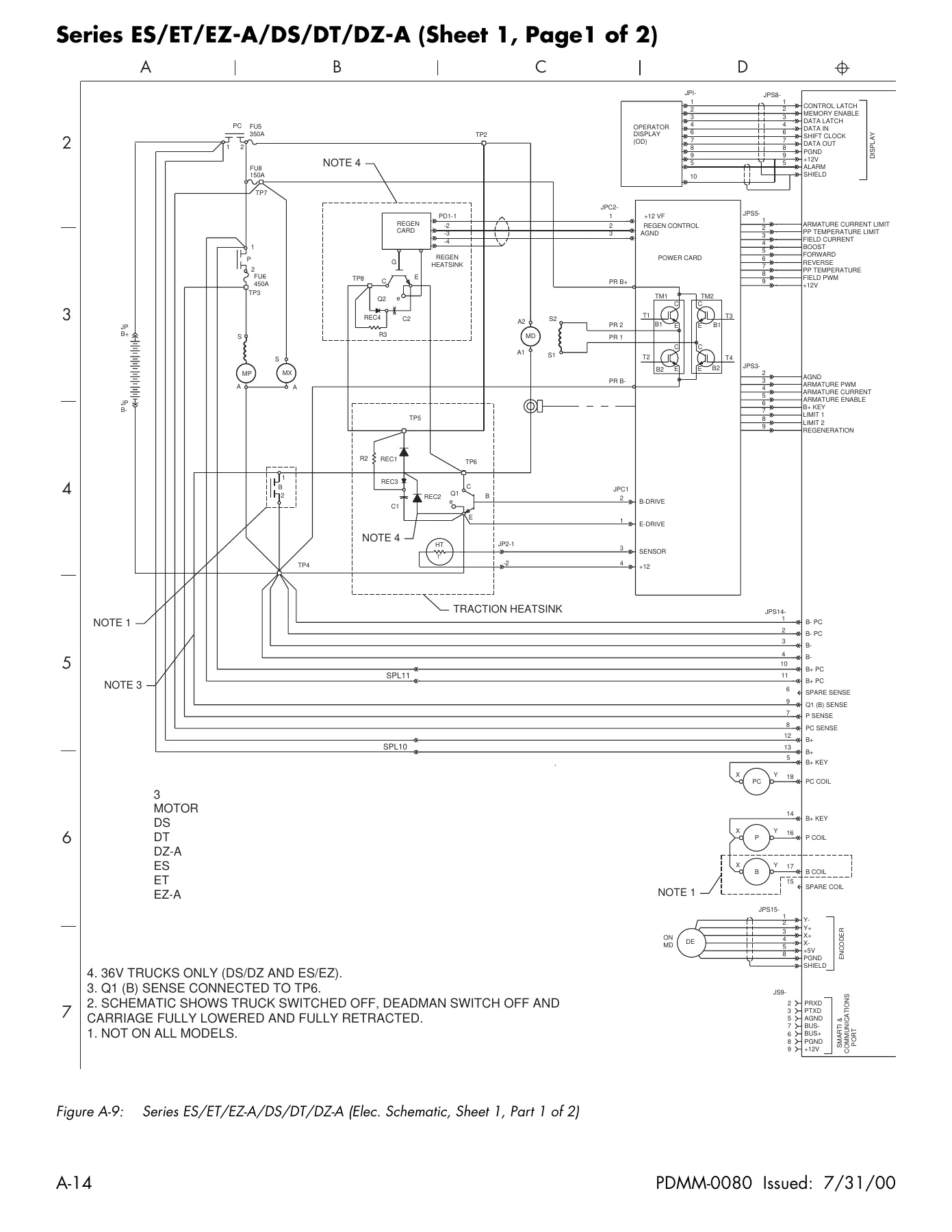
Figure A-9: Series ES/ET/EZ-A/DS/DT/DZ-A (Elec. Schematic, Sheet 1, Part 1 of 2)p. 712
Figure A-10: Series ES/ET/EZ-A/DS/DT/DZ-A (Elec. Schematic, Sheet 1, Part 2 of 2)p. 713
Figure A-11: Series EF (Elec. Schematic, Sheet 2, Part 1 of 2)p. 714
Figure A-12: Series EF (Elec. Schematic, Sheet 2, Part 2 of 2) Scale H=8.66 W=9.85p. 715
Figure A-13: Series EZ-B/DZ-B (Elec. Schematic, Sheet 1, Part 1 of 2) Scale =90%p. 716
Figure A-14: Series EZ-B/DZ-B (Elec. Schematic, Sheet 3, Part 2 of 2)Scale =90%p. 717
Figure A-15: Options (Elec. Schematic, Sheet 4, Part 1 of 3) Scale 125%p. 718
Figure A-16: Options (Elec. Schematic, Sheet 4, Part 2 of 3) Scale 95%p. 719
Figure A-17: Options (Elec. Schematic, Sheet 4, Part 3 of 3) Scale 95×95%p. 720
Figure A-18: Options (Elec. Schematic, Sheet 5, Part 1 of 3)W=6.75 H=8.25p. 721
Figure A-19: Options (Elec. Schematic, Sheet 5, Part 2 of 3) Scale W=6.75 H=8.25p. 722
Figure A-20: Options (Elec. Schematic, Sheet 5, Part 3 of 3) Scale W=6.75” H=8.25”p. 723
Figure A-21: Heater Options (Elec. Schematic, Sheet 6, Part 1 of 3)W=6.75 H=8.25p. 724
Figure A-22: Heater Options (Elec. Schematic, Sheet 6, Part 2 of 3) Scale W=6.75 H=8.25p. 725
Figure A-23: Heater Options (Elec. Schematic, Sheet 6, Part 3 of 3) Scale W=6.75” H=8.25”p. 726
Figure A-24: HTI Option (Elec. Schematic, Sheet 7, Part 1 of 2) Scale W=6.75” H=8.25”p. 727
Figure A-25: 4-D (Elec. Schematic, Sheet 7, Part 2 of 2) Scale W=6.75” H=8.25”p. 728
Figure A-26: Legend (Elec. Schematic, Sheet 8, Part 1 of 3) Scale W=6.75” H=8.25”p. 729
Figure A-27: Legend (Elec. Schematic, Sheet 5, Part 2 of 3) Scale W=6.75” H=8.25”p. 730
Figure A-28: Legend (Elec. Schematic, Sheet 5, Part 3 of 3) cale W=6.75” H=8.25”p. 731
Hydraulic Schematicsp. 733
Figure A-29: Hydraulic Schematic, Series ES/ET/EZ-A/DS/DT/DZ-BScale W=6.75” H=8.25”p. 734
Figure A-30: Hydraulic Schematic, Series EZ-B/DZ-BScale W=6.75” H=8.25”p. 735
Figure A-31: Hydraulic Schematic, Series EFle W=6.75” H=8.25”p. 736
Indexp. 737
Numericsp. 737
Ap. 737
Bp. 737
Cp. 737
Dp. 738
Ep. 738
Fp. 738
Gp. 739
Hp. 739
Ip. 739
Kp. 739
Lp. 739
Mp. 740
Op. 740
Pp. 740
Qp. 741
Rp. 741
Sp. 741
Tp. 742
Vp. 742
Wp. 743

Delivery

IMAGES PREVIEW

Raymond EASi Reach-Fork Lift Truck Maintenance Manual PDMM-0080 - EZ ET ES DS DT EF DZ Series — PDF page 1 preview
Raymond EASi Reach-Fork Lift Truck Maintenance Manual PDMM-0080 - EZ ET ES DS DT EF DZ Series — PDF page 271 preview
Raymond EASi Reach-Fork Lift Truck Maintenance Manual PDMM-0080 - EZ ET ES DS DT EF DZ Series — PDF page 712 preview

The manual is delivered as an instant PDF download after purchase. No shipping, no waiting, no physical book to store. Open it on a laptop, tablet or phone in the workshop, print only the pages you need for a job, and keep the full 746-page reference on any device that reads PDFs.
Reviews

There are no reviews yet.

Be the first to review “Raymond EASi Reach-Fork Lift Truck Maintenance Manual PDMM-0080 – EZ ET ES DS DT EF DZ Series”

What Our Customers Say

★★★★★ Live reviews from customers
Loading customer reviews...
0
    0
    Your Cart
    Your cart is emptyReturn to Shop
    🛒
    Recently Purchased
    🕒 verified order