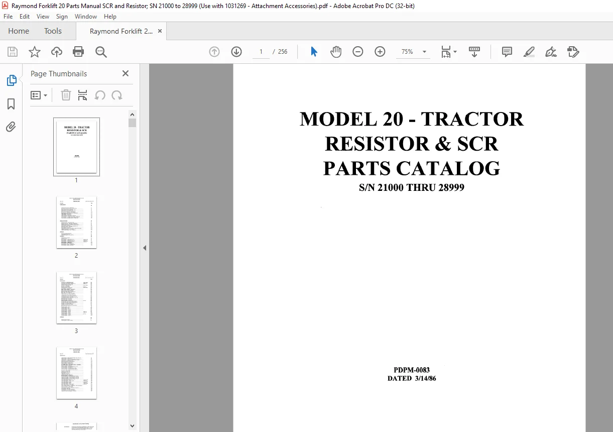
Raymond FORKLIFT 20 – TRACTOR RESISTOR & SCR PARTS CATALOG MANUAL – PDF DOWNLOAD
$27.95
Raymond FORKLIFT 20 – TRACTOR RESISTOR & SCR PARTS CATALOG MANUAL – PDF DOWNLOAD
SIN 21000 THRU 28999
Description
Raymond FORKLIFT 20 – TRACTOR RESISTOR & SCR PARTS CATALOG MANUAL – PDF DOWNLOAD
FILE DETAILS:
Raymond FORKLIFT 20 – TRACTOR RESISTOR & SCR PARTS CATALOG MANUAL – PDF DOWNLOAD
Language : English
Pages :256
Downloadable : Yes
File Type : PDF
Size:21.6 MB
DESCRIPTION:
Raymond FORKLIFT 20 – TRACTOR RESISTOR & SCR PARTS CATALOG MANUAL – PDF DOWNLOAD
SIN 21000 THRU 28999
The Raymond Corporation manufadures a variety of lift truck~ in both standard and customized configurations. The Parti Catalog is organized into major divisions which cover all areas of the truck. These may indude:
• Power Unit [If applicable) • Hydraulic (if applicable)
• Brake and Steering • Elevating/ Attachments
• Drive Unit • Contadors
• Eledrical • Special Options [If applioob~@)
Using the
Catalog
Overview
Example: The DRIVE UNIT assembly is shown on one page — the DRIVE MOTOR for this drive unit
on another page — the DRIVE WHEEL for this unit on another page.
570-000/01
570-000/02
Motor Assembly
Armature
Field Winding
570-000/01 and 570-000/02 are parts of Motor 570-000
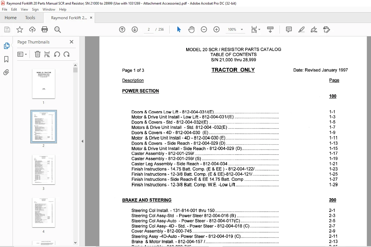
TABLE OF CONTENTS:
Raymond FORKLIFT 20 – TRACTOR RESISTOR & SCR PARTS CATALOG MANUAL – PDF DOWNLOAD
Doors & Covers Low Lift- 812-004-031/(E) 1-1
Motor & Drive Unit Install – Low Lift- 812-004-031/(E) 1-3
Doors & Covers – Std – 812-004-032/(E) 1-5
Motors & Drive Unit Install – Std 812-004 -032(E) 1-7
Doors & Covers – 4D – 812-004-030 (E) 1-9
Motor &DriveUnitlnstall-4D-812-004-030(E) 1-11
Doors & Covers -Side Reach – 812-004-029 (D) 1-13
Motor & Drive Unit Install – Side Reach – 812-004-029 (D) 1-15
Caster Assembly – 812-001-259/ 1-17
Caster Assembly – 812-001-259/ (S) 1-19
Caster Leg Assembly – Side Reach – 812-004-034 1-21
Finish lnstructions-1475 Batt Comp (E & EE) – 812-004-122/ 1-23
Finish Instructions – 12-3/8 Batt Comp (E & EE)-812-004-121/ 1-25
Finish Instructions – Side Reach-E & EE 1475 Batt Comp 1-27
Finish Instructions – 12-3/8 Batt Comp WE -Low Lift 1-29
BRAKE AND STEERING 200
Steering Col Install – 131-814-001 thru 150 2-1
Steering Col Assy-Std – Power Steer 812-004-016 (B) 2-3
Steering Col Assy-Auto – Power Steer – 812-004-017(C) 2-5
Steering Col Assy- 4D – Std – Power Steer- 812-004-018 (C) 2-7
Cover Assembly- 812-000-745 2-9
Steering Assy -4D-Auto – Power Steer- 812-004-019 (C) 2-11
Brake & Motor Install – 812-004-157 / 2-13
Brake Assembly – 812-000-745 2-15
Deadman Brake Assembly – 812-004-029 (D) ,030(E) ,031 (E), 032(E) 2-17
Deadman Pedal Install -WE- 812-004-105 2-19
Deadman Switch Assembly -WE – 812-004-110 2-21
DRIVE UNIT 300
Drive Unit Assembly -812-004-007/ 3-1
Gear Housing – 812-001-230 3-3
Drive Wheel Assembly- 812-001-840/ (C) 3-5
ELECTRICAL 400
Standard Electrical Symbols 4-1
Ref Of Elec Comp 4-3
Electrical System – 154-008-400/ Sht 1 of 2 21000 to 23483 4-5
Electrical System -154-008-400/ (G) Sht 1 of2 23484 & up 4-7
Electrical System – 154-008-400/ Sht 2 of 2 21000 to 23483 4-9
Electrical System – 154-008-400/(G) Sht 2 of 2 23484 & up 4-11
Electrical System – 154-008-430/ (D) 4-13
Electrical System – SCR -154-008-420 (E) 4-15
Electrical System – Resistor – 154-008-423/ (B) 4-17
Electrical System – Remote- 154-008-422/ 4-19
Page 2 of 3
Description
Electrical {Cont’d}
MODEL 20 SCR / RESISTOR PARTS CATALOG
TABLE OF CONTENTS
S/N 21,000 thru 28,999
TRACTOR ONLY Date: Revised January 1997
Page
Controller Assy -154-002-520/ (P) Resistor 4-21
Controller Assy – 154-002-500/ (AB) SCR 13600 to 23483 4-23
Control Electric – Mod II SCR – 154-008-518/ (D) 23484 & up 4-25
Contactor Panel Assy 154-008-435/ (B) 4-27
Panel Assy -154-008-404/ – SCR 21000 to 23483 4-29
Panel Assy- 812-004-146 (C) 4-31
Panel Assy -154-008-404/(F) 23484 &up 4-33
Contactor Panel Assy -154-007-205/ 21000 to 23483 4-35
Horn Installation- 154-005-322 (B) 4-37
Battery Connector Installation- 154-005-039 (A) 4-39
Battery Connector Assembly- 812-000-144 4-41
Heat Sink Assembly- 154-008-406/ SCR 4-43
Meter Install – SCR & Resistor – 154-008-421 (F) 4-45
Meter – Install – SCR – 812-004-146 4-47
Resistor Assembly – 812-004-091 (B) Resistor 4-49
LVCB Assembly & Install – Resistor-154-008-415/ 4-51
LVCB Assembly & Install – SCR – 154-008-413/ 4-53
Limit Switch Install – 821-001-248/ (24″ HS cut out) 4-55
Limit Switch Install – 812-001-270/ (H) (HS clear height) 4-57
Lift Limit Switch Assembly – 787-033-060/ 4-59
Limit Switch Install – 821-001-238/ (20″ & 24″ HS cut out) 4-61
Warning Light Install – 821-001-262/ 4-63
Working Lights Install – 154-007-258/ 4-65
Back-Up Light Install – 154-007-259 4-67
Control Unit Assembly – 154-005-350 (F) 001 & Up 4-69
Cord Reel Install – 812-004-176/ (A) (SCR & Resistor) 4-71
Cord Reel Switch Install – 812-002-752 (SCR & Resistor) 4-73
Drive Motor – 570-415/200 (Resistor -Prest-Lg Fr) 4-75
Drive Motor – 570-415/201 (Prest-Sh Fr) 4-77
Drive Motor- 570-415/100 (GE I SCR) 4-79
Electrical Supp Switching Solenoid – 812-001-926/ (E) 4-81
Contactor Assembly – 4-83
Contactor Assembly – 590-171 4-85
Contactor Assembly – 590-172 4-87
Contactor Assembly – 590-176 4-89
Contactor Assembly – 1-1 05-012 4-91
Contactor Assembly – 1-1 05-054 4-93
Contactor Assembly – 1-1 05-009 4-95
Contactor Assembly – 1-1 05-016 13600 & Up 4-97
Contactor Assembly – 1-105-017 13600 & Up 4-99
Contactor Assembly – 1-105-029 4-101
Contactor Assembly – 1-105-031 001 & Up 4-103
Contactor Assembly – 1-105-040 4-105
Contactor Assembly – 1-105-072 4-107
HYDRAULIC
Standard Hydraulic Symbols ,
Hydraulic System – 812-004-163 (W/lift)
Date: Revised January 1997
Hydraulic System – 812-004-167/ (w/Power Steer, w/Aux) Sht 1 of 2 5-5
Hydraulic System – 812-004-167/ (L) 5-7
Hydraulic System – 812-004-167 (w/Power Steer, w/o Aux)Sht 2 of 2 5-9
Hydraulic System – 812-004-237/(B) (Straddle w/Aux Function 5-11
Vale Assembly – 812-002-696 (Low Lift) 5-13
Solenoid Valve Assembly – 520-449 (Low Lift) 5-15
Valve Lock Assembly – 520-307 (Low Lift) 5-17
Manifold Assembly – 812-004-166/ (D) 5-19
Lift/Lower Manifold – 520-825/001 & /002 5-21
Aux Controls Piping – 812-002-099/(C) & 100/ (C) 1,2,3,spl valves 5-23
Reservoir Assembly – 812-004-024 5-25
Lift Pump And Motor – 812-002-604(8) Prest Sh Fr “EE” 5-27
Lift Punp And Motor – 812-002-630 (E) 5-29
Lift Pump And Motor – 812-002-630 (E) (GE Type E 5-31
Lift Pump And Motor – 812-002-604 (B) (GE Type EE 5-33
Lift Pump And Motor – 812-002-604 (B) (Hitachi Type EE) 5-35
Lift Pump And Motor- 812-002-630 (E) (Hitachi Type E) 5-37
Auxiliary Pump – 500-417/200 5-39
Auxilary Pump – 500-417/100 5-41
Motor Assembly – 570-214/101 5-43
Auxiliary Motor – 570-214 5-45
Auxiliary Motor – 570-214/100 5-47
Auxiliary Pump & Motor- 812-004-147 5-49
Motor Steer Assembly – 812-002-623 (F) 5-51
Lift Valve Installation – 812-004-029 (D), 030 (E), & 032 (E) 5-53
Auxiliary Valve lnstalltion – 812-002-169 (RIE1) 1 spool valve 5-55
Auxiliary Valve lnstalltion – 812-002-170 (RIE1) 2 spool valve 5-57
Auxiliary Valve lnstalltion – 812-002-171 (RIE1) 3 spool valve 5-59
Control Valve Assembly (Lift)- 812-004-141 (C) 5-61
Control Valve Assembly – 520-043 13600 to 24499 5-63
Control Valve Assembly – 520-075 (1 spool) 24500 & Up 5-65
Control Valve Assembly – 520-066 15212 to 24499 5-67
Control Valve Assembly – 520-076 24500 & Up 5-69
Control Valve Assembly – 520-053 13600 to 24499 5-71
Control Valve Assembly – 520-077 (3 spool) 24500 & Up 5-73
Piping – Tractor To Attach – 812-000-492 5-75
Tractor To Attachment Piping – 112-000-669/(C) , 769/ (C) (Side Reach) 5-77
Piping – Tractor To Attach – 761-151-089 5-79
Hydraulic Supplement – 812-001-896 (B) 5-81
Switching Solenoid Installation – 812-001-920/, 812-001-911/ 5-83
Pump Assembly – 500-417 /201 5-85
Valve Assembly – 812-001-956 (2 spool Valve) 5-87
Valve Assembly – 812-001-957 (3 spool Valve) 5-89
Hydraulic Ram Feed Line Installation – 812-005-061/ 5-91
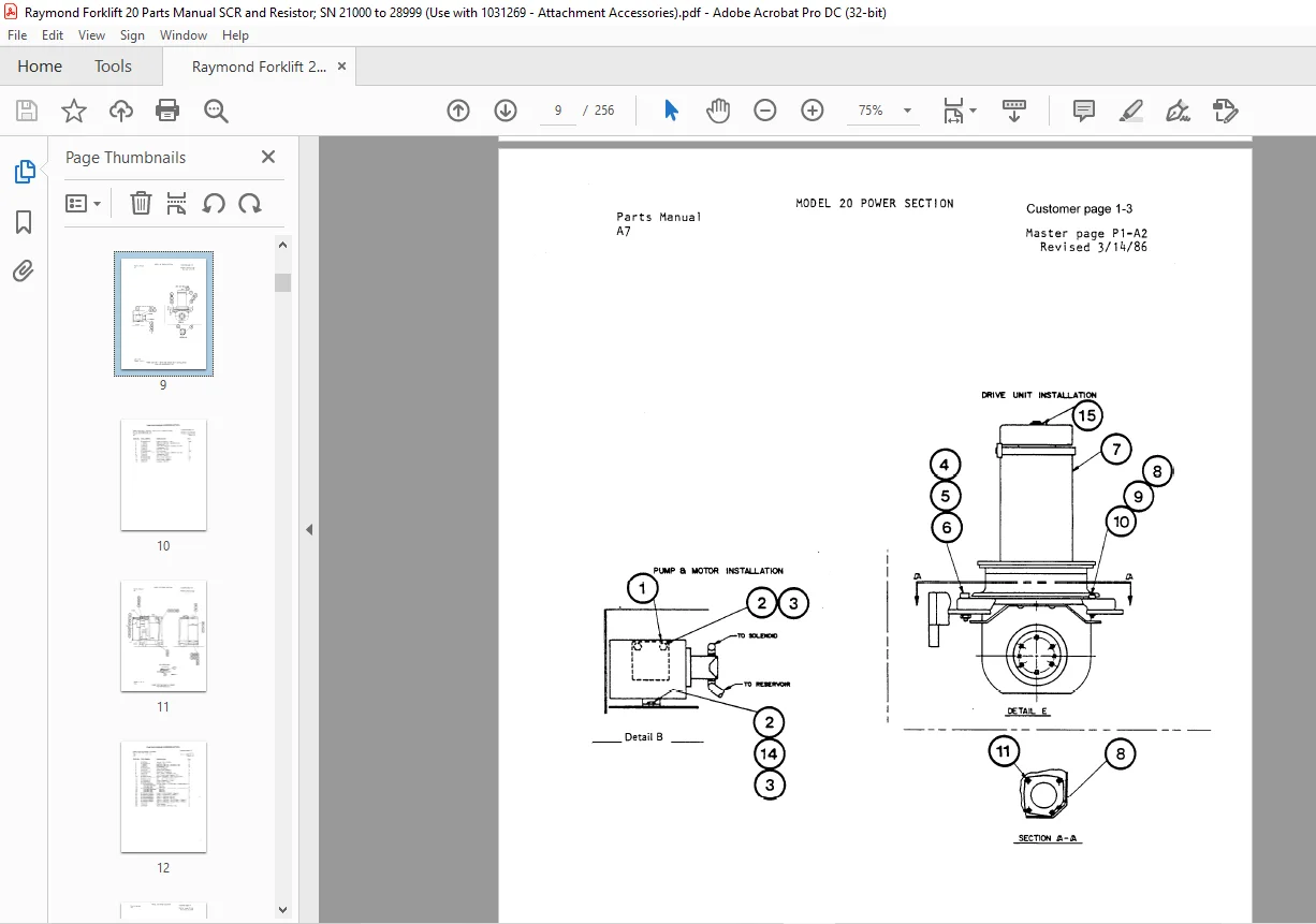
IMAGES PREVIEW OF THE MANUAL:
Need help? Contact: [email protected]
https://vimeo.com/837464676?share=copy
PLEASE NOTE:
- This is the SAME exact manual used by your dealers to fix your vehicle.
- The same can be yours in the next 2-3 mins as you will be directed to the download page immediately after paying for the manual.
- Any queries / doubts regarding your purchase, please feel free to contact [email protected]
S.M