Raymond FORKLIFT 20SCR Operation & Maintenance Instructions Manual 13600-20,999 – PDF DOWNLOAD
$25.95
Raymond FORKLIFT 20SCR Operation & Maintenance Instructions Manual 13600-20,999 – PDF DOWNLOAD
Description
Raymond FORKLIFT 20SCR Operation & Maintenance Instructions Manual 13600-20,999 – PDF DOWNLOAD
FILE DETAILS:
Raymond FORKLIFT 20SCR Operation & Maintenance Instructions Manual 13600-20999 – PDF DOWNLOAD
Language : English
Pages :165
Downloadable : Yes
File Type : PDF
Size:21.9 mb
DESCRIPTION:
Raymond FORKLIFT 20SCR Operation & Maintenance Instructions Manual 13600-20999 – PDF DOWNLOAD
INTRODUCTION
- 1-1 This manual provides the Description, Operating Instructions, Installation, Theory of Operation, Maintenance and Troubleshooting Instructions for the Raymond Model 20 SCR trucks. Figure 1-1 shows a Model 20 Reach-Fork truck.
- 1-2 The Model 20 power lift truck is primarily built for general indoor warehouse use, or for bulk storage outdoors on paved ~r other hard surfaces. The truck is a stand-up rider type designed for narrow aisle installations. Right angle stacking of palletized loads can be accomplished in aisles as narrow as 6 feet.
- 1-3 Power for the Model 20 SCR truck is provided by a 24 volt industrial battery. The Model 20 truck has the ability, for example, to carry a 2,000 lb. load at speeds up to 5 miles per hour, to elevate at speeds up to 40 feet per minute, and to stack loads at heights up to 240 inches. These factors plus its exceptional maneuverability make the Model 20 truck the leading performer of 24 volt narrow aisle trucks.
- 1-4 Model 20 series trucks are available in 2000, 3000, and 4000 pound capacities and can be provided with straddle, reachfork, deep reach, scrambler low-lift platform and fork, 40 (four directional), high lift pallet, or sidereach attachments. The mast is offered in either two or three stage construction. A variety of collapsed and elevated heights are available to fit most applications. In addition, various optional features such as power tilt, sideshift, clamp, etc., adapt the truck to specific situations. Model 20 SCR trucks have, as a standard feature, U.L. type E approval. Type EE approval is optional.
- 1-5 Power steering is standard on all Model 20 trucks. Other conveniences which the trucks offer are a low step in compartment (only 11″ high) and the convenient location of the controls. Controls are located so the operator can drive facing either towards or away from the load. The operator controls steering with one hand while travel direction and speed, lift, lower, and auxiliary functions are all within easy reach of the other hand.
- 1-6 The Model 20 SCR truck incorporates the use of electronic semi-conductors to control travel speeds. This system provides the operator with an infinite selection of travel speeds, from slow inching to approximately 4½ miles per hour. The truck has a non-variable higher speed giving a top speed of 5 miles per hour.
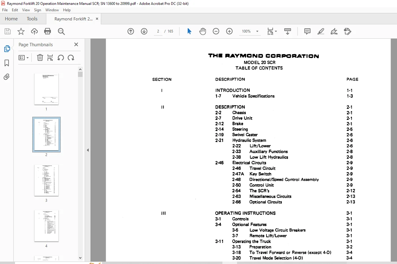
TABLE OF CONTENTS:
Raymond FORKLIFT 20SCR Operation & Maintenance Instructions Manual 13600-20999 – PDF DOWNLOAD
DESCRIPTION PAGE
INTRODUCTION 1-1
1-7 Vehicle Specifications 1-3
II DESCRIPTION 2-1
2-2 Chassis 2-1
2-7 Drive Unit 2-1
2-12 Brake 2-1
2-14 Steering 2-5
2-19 Swivel Caster 2-6
2-21 Hydraulic System 2-6
2-22 Lift/Lower 2-6
2-33 Auxiliary Functions 2-8
2-38 Low Lift Hydraulics 2-8
2-45 Electrical Circuits 2-9
2-46 Travel Circuit 2-9
2-47A Key Switch 2-9
2-48 Directional/Speed Control Assembly 2-9
2-50 Control Unit 2-9
2-54 The SCR’s 2-12
2-63 Miscellaneous Circuits Z-1″3
2-66 Optional Circuits 2-13
111 OPERATING INSTRUCTIONS 3-1
3-1 Controls 3-1
3-4 Optional Features 3-1
3-5 Low Voltage Circuit Breakers 3-1
3-7 Remote Lift/Lower 3-1
3-11 Operating the Truck 3-1
3-13 Preparation 3-2
3-18 To Travel Forward or Reverse (except 4-0) 3-4
3-20 Travel Mode Selection (4-0) 3-4
3-22 Caster LoaJ Wheels ( 4-0) 3-4
3-24 To Travel Forward or Reverse 3-4
3-26 To Travel Sideways (4-0) 3-5
3-28 To Brake 3-5
3-31 Plugging 3-5
3.35 Lift/Lower 3-5
3-38 Operating the Auxiliary Functions 3-6
3-40 Ramp Operation 3-6
3-43 To Turn Into An Aisle 3-6
3-45. Entering and Leaving Pallets 3-7
a. With A Straddle Truck 3-7
b. With A Reach Truck 3-7
3-46 Entering and Leaving Skids or Pallets (Low
Lift Trucks) 3-7
3-48 Handling Long Loads 3-7
3-51 Parking the Truck 3-8
3-53 SAFETY 3-8
TH ■ “AYMCINCI C0SIP0~AT10N
MODEL 20 SCR
TABLE OF CONTENTS (cont’d.)
SECTION DESCRIPTION PAGE
IV INSTALLATION 4-1
4-3 Battery and Charger 4-1
4-8 Truck Operational Check 4-1
V THEORY OF OPERATION 5-1
5-2 Lift/Lower System 5-1
5-3 Lift 5-1
5-5 Lowering 5-1
5-7 Travel Lift/Lower 5-1
5-9 Power Steering 5-3
5-12 Auxiliary Hydraulic System 5-3
5-16 Reach, Power Tilt, etc. 5-3
5-19 Hydraulic – Low Lifts 5-5
5-21 Travel System 5-6
5-24 What Is An SCR? 5-6
5-29 SCR Applications 5-7
5-36 Operation of the Travel System 5-9
VI MAINTENANCE 6-1
6-1 Scheduled Maintenance 6-1
6-3 Drive Unit 6-7
6-6 To Clean and Inspect the Drive Motor 6-7
6-7 To Replace the Drive Motor 6-7
6-8 To Replace the Drive Wheel 6-10
6-9 To Remove and Disassemble the Drive Unit 6-13
6-10 To Reinstall the Drive Unit 6-14
6-11 The Brake 6-15
6-18 Steering 6-17
6-20 To Remove the Steering Assembly 6-18
6-21 To Disassemble the Steering Assembly 6-20
6-24 Swivel Caster 6-22
6-28 Adjustment of the Swivel Caster 6-23
6-31 Hydraulic 6-24
6-32 General 6-24
6-41 Hydraulic Oil and Filter 6-25
6-43 Bleeding Air From the Lift Cylinder 6-25
6-45 Lift and Auxiliary Pumps 6-26
6-49 Lift/Lower Control Valve 6-26
6-51 Manifold Assembly 6-26
6-53 Lift Pressure Relief Valve 6-26
6-56 Low Pressure Relief Valve 6-27
6-58 Solenoid Valves 6-27
6-62 Auxiliary Control Valve 6-28
6-64 Auxiliary Valve Pressure Relief 6-28
6-67 Electrical 6-29
6-68 Battery 6-29
6-86 Motors 6-31
6-98 Contactors 6-33
6-114 Directional/Speed Control Assembly 6-41
6-122 Control Unit 6-44
6-160 Plugging Relay K2 6-50
6-162 Transient Suppressors 6-50
Diode Assemblies
Resistor Assemblies
Low Voltage Circuit Breaker
Testing Other Electrical Components
Lift Chain
TRUCK PROBLEM
The Truck Is Completely Inoperative 7-3
There Is No Reach, Tilt, Sideshift or Power
Steering 7-8
There Is No Lift – The Truck Travels OK
and Has Auxiliary Functions 7-9
The Truck Has No Travel – All Other
Circuits Function 7-11
The Truck Has No Reverse Travel But There
Is Forward Travel 7-19
The Truck Has No Forward Travel But
There Is Reverse Travel 7-20
The Truck Has No “M” Speed Range –
Operates Properly in SCA Range 7-21
The Truck Runs at Approximately Half
Speed in the SCR Range 7-23
The Truck Develops Top Speed Throughout
the SCR Range 7-24
The Truck Acceleration is Jerky in the SCA
Range 7-25
The Truck Reacts Violently When Plugged 7-26
The Overload Kicks Out During Operation 7-27
The Truck Stalls While Going Up a Ramp 7-30
Remote Lift/Lower Problems 7-32
Auxiliary Systems Problems
Lift/Lower Circuit Problems
The Horn is Inoperative
Hydraulic Problems
LIST OF ILLUSTRATIONS
TITLE
Model 20 SCA Reach-Fork Truck
Vehicle Specifications
Model 20 SCA with Door Open and Covers Removed
Cross Section of Complete Drive Unit
Brake Installation
Gears for Automotive and Standard Steering
Identifying Hydraulic Components
Electrical Panel
Standard Model 20 Truck Controls
Remote Lift/Lower Controls
“4-0” Caster Controls and Direction Indicators
Figure 3-4-Defining Travel Directions and Truck Wheels
Straddle Truck Entering Pallet
Reach Truck Entering Pallet
Model 20 Warning Safety Decal
Hydraulic Schematic
Low Lift Hydraulic Schematic
SCR’s Physical Appearance and Electrical Symbol
Diagram of How an SCA Operates
Simplified Diagram of a Resistor Controlled Truck
Circuit with Speed Switch
Battery and Voltmeter Hook-up
Simplified Circuit Using an SCA
Model 20 SCA Electrical Schematic
Keyswitch S1 Turned To ON
Deadman Pedal Depressed
Directional Switch Closed
Turning ON The Main SCA and the Charging SCA
Turning OFF the Main SCA
Recirculating the Current After the Main SCA 1 Has Been Turned OFF
High Speed Switch Closed
Plugging
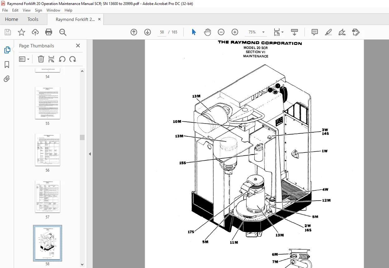
Tractor Inspection and Lubrication Chart
Tractor Lubrication and Inspection Points
Straddle Attachment Lubrication
Reach Fork Attachment Lubrication
Drive Motor Installation
Drive Unit
Cross Section of the Drive Unit
Drive Wheel
Fabricated Ring for Removing the Drive Unit
Proper Position of the Thrust and Radial Rings
Exploded View of the Brake Assembly
View of the Brake System
Adjustment of the Brake Pedal
Steering Column Assembly – Power Steering – Automotive Type
Exploded View of the Caster
Pre-loading Caster Springs
View of Hydraulic Components
A Maximum Rate of Allowable Load Drop
Hydraulic Control Valves
Table of Brush Lengths and Spring Pressures
Drive Motor Terminals and Circuits
Identification of Contactors
“M” Contactor
“X” Contactor
FR Contactor
PC Contactor
P Contactor
Potentiometer Terminals
Directional/Speed Control Assembly
Adjustments and Test Pins of the Control Unit
Exploded View of the Control Unit
Current Shunt and Meter Arrangement
Test Circuit for M, F and R Coil Suppressors
Module Assemblies
Test Circuit for the Low Voltage Circuit Breaker
low Voltage Circuit Breaker
Electrical Components Test
SCA and Rectifier Torque Ratings and Installation
lubricate Chain Joints to Prevent Wear
Standard Torque Data for Bolts
lubrication Equivalent Chart
Wiring Diagram for the Model 20 Truck
IMAGES PREVIEW OF THE MANUAL:
Questions? Email us: [email protected]
PLEASE NOTE:
- This is the SAME exact manual used by your dealers to fix your vehicle.
- The same can be yours in the next 2-3 mins as you will be directed to the download page immediately after paying for the manual.
- Any queries / doubts regarding your purchase, please feel free to contact [email protected]
s.m