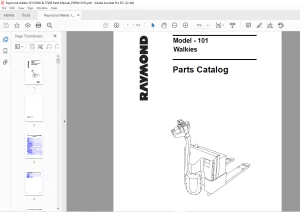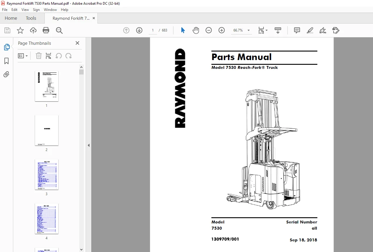
Raymond Forklift 7530 Reach-Fork ® Trucks Parts Manual – PDF DOWNLOAD
$33.95
Raymond Forklift 7530 Reach-Fork ® Trucks Parts Manual – PDF DOWNLOAD
Description
Raymond Forklift 7530 Reach-Fork ® Trucks Parts Manual – PDF DOWNLOAD
FILE DETAILS:
Raymond Forklift 7530 Reach-Fork ® Trucks Parts Manual – PDF DOWNLOAD
Language : English
Pages : 683
Downloadable : Yes
File Type : PDF
Size:97.3 MB
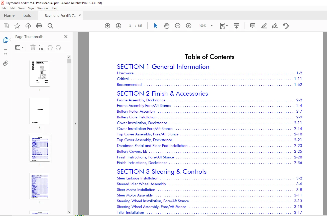
TABLE OF CONTENTS:
Raymond Forklift 7530 Reach-Fork ® Trucks Parts Manual – PDF DOWNLOAD
SECTION 1 General Information
Hardware 1-2
Critical 1-11
Recommended 1-62
SECTION 2 Finish & Accessories
Frame Assembly, Dockstance 2-2
Frame Assembly Fore/Aft Stance 2-4
Battery Roller Assembly 2-7
Battery Gate Installation 2-9
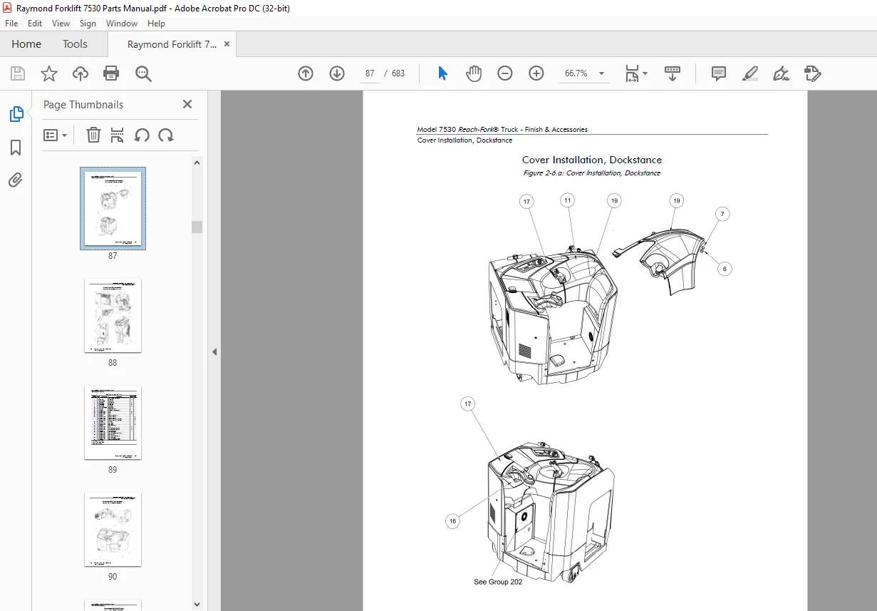
Cover Installation, Dockstance 2-11
Cover Installation Fore/Aft Stance 2-14
Top Cover Assembly, Fore/Aft Stance 2-18
Top Cover Assembly, Dockstance 2-21
Deadman Pedal and Floor Pad Installation 2-23
Battery Covers, EE 2-25
Finish Instructions, Fore/Aft Stance 2-28
Finish Instructions, Dockstance 2-36
SECTION 3 Steering & Controls
Steer Linkage Installation 3-2
Steered Idler Wheel Assembly 3-6
Steer Motor Installation 3-8
Steer Motor Assembly 3-11
Steering Wheel Installation, Fore/Aft Stance 3-13
Steering Wheel Assembly, Fore/Aft Stance 3-15
Tiller Installation 3-17
Control Handle Installation 3-19
Control Handle Assembly, Fore/Aft Stance, Primary 3-22
Control Handle Assembly, Fore/Aft Stance, Primary, ThermaKit 3-27
Control Handle Assembly, Dockstance, Standard and Cold Storage 3-30
Control Handle Assembly, Dockstance, ThermaKit 3-32
Control Handle Installation, Fore/Aft Stance, Secondary 3-36
Control Handle Assembly, Fore/Aft Stance, Secondary 3-38
Control Handle Assembly, Fore/Aft Stance, Secondary, ThermaKit 3-40
Control Assembly, Thermakit 3-43
SECTION 4 Drive & Brake
Drive Unit Installation 4-2
Drive Unit Assembly 4-4
Traction Motor Installation 4-7
Brake Installation 4-9
Brake Assembly 4-11
Deadman Pedal Installation 4-13
Drive Wheel Installation 4-17
Inertial Damper Assembly 4-19
SECTION 5 Electrical Comp. & System
Electrical System Fore/Aft Stance 5-2
Electrical System, Dockstance 5-7
Traction Power Amplifier Installation 5-12
Traction Power Amplifier Assembly 5-14
Lift Power Amplifier Installation 5-16
Lift Power Amplifier Assembly 5-18
Auxiliary Controller Installation 5-20
Vehicle Manager Installation 5-22
Contactor Panel Installation 5-24
Contactor Panel Assembly 5-26
Contactor Assembly 5-29
Drive Motor Assembly, Standard 5-31
Drive Motor Assembly, EE 5-33
Drive Motor, EE 5-35
Lift Motor Assembly, Standard 5-37
Lift Motor Assembly (EE) 5-39
Auxiliary Motor Assembly 5-41
7 Inch Evolution Display Installation 5-43
Dash Panel Installation, Fore/Aft Stance 5-46
Dash Panel Installation, Dockstance 5-48
Horn Installation, Fore/Aft Stance 5-50
Horn Installation, Dockstance 5-53
Key Switch Installation 5-56
Relay/Control Fuse Panel Installation with Auxiliary Power 5-58
Battery Connector Installation 5-61
Battery Connector Assembly 5-63
Freelift Encoder Installation 5-65
Main Lift Height Encoder Installation 5-67
Freelift Encoder Assembly 5-69
Main Lift Height Encoder Assembly 5-71
Sensor Installation, Ambient Temperature, 5-73
Fan Assembly, Drive Motor Compartment 5-75
Fan Assembly, Lift Motor Compartment 5-77
SECTION 6 Hydraulic Components
Lift Hose Installation 6-2
Reservoir Installation 6-5
Reservoir Assembly 6-7
Lift Pump and Motor Installation 6-10
Lift Pump and Motor Assembly 6-12
Pump and Manifold Assembly 6-14
Auxiliary Pump and Motor Installation 6-16
Auxiliary Pump and Motor Assembly 6-18
Main Manifold Installation 6-20
Main Manifold Assembly 6-22
Auxiliary Manifold Installation 6-25
Auxiliary Manifold Assembly 6-27
Manifold Assembly, Std Reach 6-29
Manifold Assembly, Deep Reach 6-31
Tilt Manifold Assembly 6-33
Tilt and Sideshift Manifold Assembly 6-35
Main Lift Cylinder Assembly 6-38
Freelift Cylinder Assembly 6-45
Reach Cylinder Assembly 6-62
Tilt Cylinder Assembly 6-64
Sideshift Cylinder Assembly 6-66
SECTION 7 Mast
Mast to Tractor Mounting and Brace Installation 7-2
Elevating Section, R45TT, DR32TT 7-10
Main Lift Cylinder Installation 7-18
Freelift Cylinder Installation, R45TT 7-21
Freelift Cylinder Installation, DR32TT 7-23
Freelift Chain Installation 7-25
Over Head Guard Installation 7-35
Hose Installation, Mast (5/8 in.) 7-37
Hose and Cable Installation 7-43
Over the Mast Cable Installation 7-55
Fixed Carriage Installation, R45TT 7-59
Reach Carriage Assembly, R45TT 7-62
Scissors Assembly, R45TT 7-64
Fixed Carriage Installation, DR32TT 7-66
Reach Carriage Assembly, DR32TT 7-68
Scissors Assembly, DR32TT 7-72
Hose and Cable Installation, Carriage, R45TT 7-74
Hose and Cable Installation, Carriage, DR32TT 7-77
Carriage Assembly, Tilt without Sideshift, R45TT 7-80
Carriage Assembly, Tilt, DR32TT 7-82
Carriage Assembly, Tilt and Sideshift, R45TT 7-84
Tilt and Sideshift Piping, R45TT 7-86
Carriage Assembly, Tilt and Sideshift, DR32TT 7-88
Carriage Subassembly, Tilt and Sideshift, R45TT 7-90
Carriage Subassembly, Sideshift, DR32TT 7-92
Glass Mast Guard 7-94
Mesh Mast Guard 7-98
Baseleg Installation, R45TT, 6 x 4 in., Open Toe 7-103
Baseleg Installation, R45TT, 6 x 4 in., Closed Toe 7-105
Baseleg Installation, DR32TT, 5 x 3.62 in., Closed Toe 7-107
Wheel Plate Installation, 6 x 4 in., Open Toe 7-109
Wheel Plate Installation, 6 x 4 in., Closed Toe 7-111
Wheel Plate Installation, 5 X 3.62 in., Closed Toe 7-113
Load Wheel Assembly 7-115
Stop Assembly 7-117
Fork Installation 7-119
SECTION 8 Options & Kits
Security Start Switch 8-2
Strobe Light (LED Warning), Aux Installation 8-4
Travel Light and Alarm Installation 8-6
Travel Alarm Installation 8-11
Light Assembly, LED 8-13
Travel Light and Fan Installation (LED) 8-15
Fan Assembly, Operator Cooling 8-17
Dome Light Installation 8-19
Auxiliary Light Assembly 8-21
Operator Compartment Sensor System (OCSS), Fore/Aft Stance 8-23
Operator Compartment Sensor System (OCSS), Dockstance 8-26
Rear Door Installation, Fore/Aft Stance 8-28
Rear Door Installation, Dockstance 8-30
Battery Connector Assembly 8-32
Rear Post, Guard, Fore/Aft Stance 8-34
Rear Post, Guard, Fore/Aft Stance With Bracket 8-36
Rear Post and Operator Backrest Installation, Dockstance 8-38
Fire Extinguisher Installation 8-40
Overhead Guard Covers 8-42
Overhead Guard Covers, Plexiglass 8-44
ThermaKit Control Installation 8-46
Tilt Carriage Shims 8-48
SideShift Fitting-Guard Installation 8-51
Nested Switch, Reach Interlock and/Or Vertical Hold 8-53
Battery Gate Alarm Installation 8-55
Battery Gate Alarm Installation 8-57
Fork-Laser System Installation 8-59
RF Adjustable Linkage Installation 8-64
Floor Spot Light Installation, Blue LED 8-67
Kit, Vantage Point Installation 8-69
Bracket Assembly, Camera (Barrel Lens Module) 8-73
Battery Connector Installation, EURO 8-75
Battery Connector Euro Pigtail 8-77
Load Backrest Installation 8-79
©The Raymond Corporation – 1309709/001
Generated Sep 18, 2018
APPENDIX A Alphabetical Parts Index
APPENDIX B Numerical Parts Index
IMAGES PREVIEW OF THE MANUAL:
Need help? Contact: [email protected]
PLEASE NOTE:
- This is the same manual used by the dealers to diagnose and troubleshoot your vehicle
- You will be directed to the download page as soon as the purchase is completed. The whole payment and downloading process will take anywhere between 2-5 minutes
- Need any other service / repair / parts manual, please feel free to contact [email protected] . We still have 50,000 manuals unlisted
s.m