Raymond Forklift DSS300 350 Counterbalanced Truck Maintenance Manual SNDSS-00-05000 and up – PDF DOWNLOAD
$31.95
Raymond Forklift DSS300 350 Counterbalanced Truck Maintenance Manual SNDSS-00-05000 and up – PDF DOWNLOAD
Description
Raymond Forklift DSS300 350 Counterbalanced Truck Maintenance Manual SNDSS-00-05000 and up – PDF DOWNLOAD
FILE DETAILS:
Raymond Forklift DSS300 350 Counterbalanced Truck Maintenance Manual SNDSS-00-05000 and up – PDF DOWNLOAD
Language : English
Pages :544
Downloadable : Yes
File Type : PDF
Size:7.94 MB
DESCRIPTION:
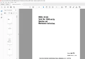
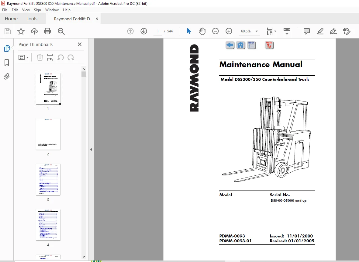
Raymond Forklift DSS300 350 Counterbalanced Truck Maintenance Manual SNDSS-00-05000 and up – PDF DOWNLOAD
How to Use this Manual
This truck has a self-diagnostic system to assist you in troubleshooting a problem. If there is a problem, the truck’s Operator Display will show a Fault Code to help you determine the cause of the problem.
Maintenance Guidelines
A regularly scheduled maintenance program is recommended to enable:
• Maximum truck performance
• Maximum truck life
• Reduction of costly down time
• Avoidance of unnecessary repairs
Scheduled maintenance includes:
• Lubrication
• Cleaning
• Inspection
• Service
Perform all the scheduled checks and maintenance during the suggested intervals. The time intervals given in this guide are based on normal operating conditions. When operating under abnormal or severe conditions, perform these services more often as required to keep the unit in good operating condition.
See page 1-9 for lubrication equivalents. Refer to the manufacturer’s supplements for components not listed on the following pages
TABLE OF CONTENTS:
Raymond Forklift DSS300 350 Counterbalanced Truck Maintenance Manual SNDSS-00-05000 and up – PDF DOWNLOAD
General 1-1
How to Use this Manual 1-2
If a Fault Code is Shown on the Operator Display 1-2
If No Fault Code is Shown on the Operator Display 1-2
Truck Directions 1-3
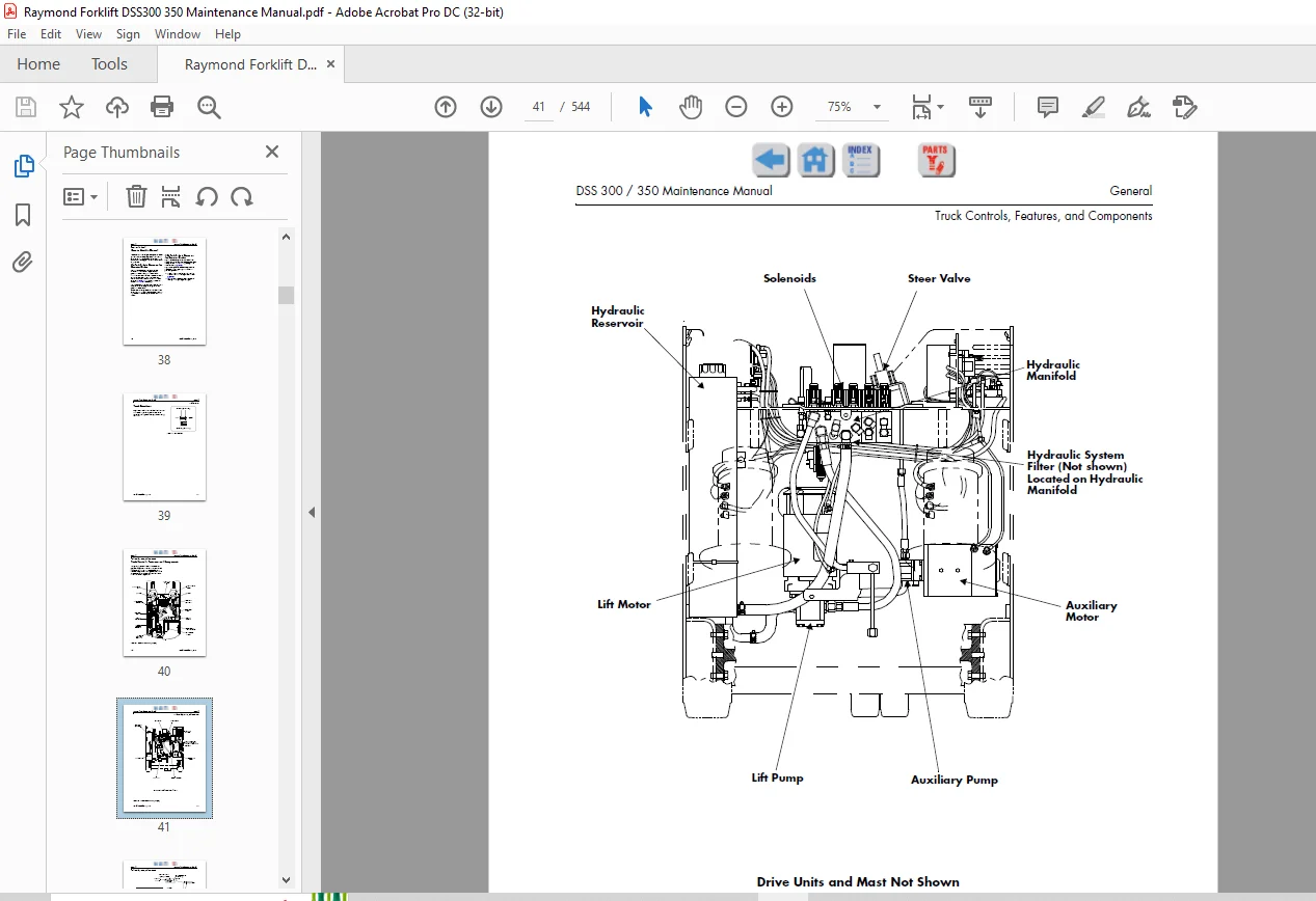
Truck Controls, Features, and Components 1-4
Jacking 1-8
Oils and Lubricants 1-9
Lubrication and Maintenance Points 1-11
Maintenance Guidelines 1-13
Handling Electronic Assemblies 1-21
Static Discharge Wrist Band 1-22
Wiring 1-23
Safety 2-1
General Safety 2-2
Battery Safety 2-6
Troubleshooting 3-1
General Troubleshooting Steps 3-2
Checking for Shorts from Battery to Truck Frame 3-2
Explanation of a Typical Troubleshooting Chart 3-3
Fuse Locations: Accessory Power Fuses, Option Fuses 3-5
Operator Display Problems 3-6
Travel Problems 3-9
Lift and/or Lower Problems 3-16
Lift Problems 3-17
Lift and Lower Problems 3-22
Lower Problems 3-25
Tilt Problems 3-27
Auxiliary Problems (Sideshift, etc ) 3-31
Attachment Problems with the Variable Pressure Auxiliary Option 3-33
Attachment Problems without the Variable Pressure Auxiliary Option 3-34
Table of Contents DSS 300 / 350 Maintenance Manual
ii Issued: November 01, 2000
Attachment Problems 3-35
Travel Alarm Problems 3-36
Working Lights Problems 3-37
Horn Problems 3-38
Operator Display Alarm Problems 3-40
Brake Problems 3-46
Steering Problems 3-48
Warning Light Does Not Work 3-50
End of Troubleshooting Procedure 3-51
Messages, Codes, and Tests 4-1
Modes 4-2
The Configure Mode 4-2
Maintenance Mode 4-6
Learn Mode 4-6
Active Maintenance Mode 4-9
Passwords 4-11
Preliminary Steps 4-11
Entering a Password 4-14
Fault Codes 4-19
Code 1H – Overheated, Allow Time to Cool
Traction Power Panel Overheated, Allow Time To Cool 4-21
Code 1L – Lift Emergency Stop Button
Emergency Power Off Switch has been Detected Down 4-22
Code 1T – Battery Low, No Lift
Lift Cutout Point Configured for Battery State-of-Charge (BSOC) Reached4-23
Code 1V – Overheated, Allow Time to Cool
Lift Power Panel Overheated 4-24
Code 20 – Speed Limited
Temperature Sensor Circuits Not Responding 4-25
Code 21 – Shutdown
Short Detected in Main Transistor Circuit 4-26
Code 23 – Drive Shutdown
Open Detected in Main Transistor Circuit 4-27
Code 24 – Drive Shutdown
Main Transistor Current Sensor Circuit Not Responding 4-28
DSS 300 / 350 Maintenance Manual Table of Contents
Issued: November 01, 2000 iii
Code 25 – Drive Shutdown
Short Detected in Field Circuit #1 4-29
Code 26 – Drive Shutdown
Open Detected in Field Circuit #1 4-30
Code 28 – Speed Limited
Excessive Acceleration 4-31
Code 29 – Speed Limited
No Movement Detected When Travel is Requested 4-32
Code 2A – Overheated, Allow Time to Cool
Traction Motor #1 Overheated 4-33
Code 2B – Drive Shutdown
Main Transistor Current Sensor Out-of-Range 4-34
Code 2C – Speed Limited
(Traction) Power Panel (Heatsink) Temperature Sensor Out-of-Range 4-35
Code 2D – Drive Shutdown
Field Current Sensor #1 is Out-of-Range 4-36
Code 2F – Speed Limited
Failure Detected in Regen Circuit 4-37
Code 2H – Speed Limited
Failure Detected in Velocity Feedback Circuit #1 4-38
Code 2J – Drive Shutdown
Failure Detected in Plugging Circuit 4-39
Code 44 – Shutdown
PC Contactor Detected Closed When Commanded Open 4-40
Code 45 – Shutdown
PC Contactor Detected Open When Commanded Closed 4-41
Code 49 – Speed Limited
X Contactor Detected Closed When Commanded Open 4-42
Code 4A – Speed Limited
X Contactor Detected Open When Commanded Closed 4-43
Code 6D – Auxiliary Shutdown
Pressure Transducer is Out-of-Range 4-44
Code 6Q – Shutdown
Lift Circuit Detected Shorted 4-45
Code 6R – Lift Shutdown
Lift Circuit Detected Open 4-46
Code 6S – Lift Shutdown
Lift Power Panel Temperature Sensor Out-of-Range 4-47
Code 6T – Lift Shutdown
Table of Contents DSS 300 / 350 Maintenance Manual
iv Issued: November 01, 2000
Lift Current Sensor Out-of-Range 4-48
Code 80 – Drive Shutdown
Throttle Controller Reading Out-of-Range 4-49
Code 81 – Lift Shutdown
Lift Controller Reading Out-of-Range 4-50
Code A0 – Shutdown
Incorrect Software for Proper Vehicle Operation 4-51
Code AG – Speed Limited
Communications to Operator Display Failed 4-52
Code AH – Speed Limited
Bad Operator Display Checksum 4-53
Code AJ – Shutdown
Defective ROM 4-54
Code AK – Shutdown
Defective RAM 4-55
Code AL – Shutdown
Defective Battery Backed RAM 4-56
Code EC – Shutdown
Operating System Error 4-57
Code F4 – Shutdown
Computer Card COP Timeout 4-58
Code F5 – Shutdown
Computer Card Invalid OP Code 4-59
Code F6 – Shutdown
Computer Card, WSI, or CAN Reset 4-60
Code F8 – Shutdown
Computer Card COP Not Enabled 4-61
Code FG – Check Battery
Vehicle Manager +12 Volt Sense Reading Out-of-Range 4-62
Code FH – Check Battery
Battery Voltage Out-of-Range 4-63
Code G2 – Speed Limited
No Steer Position Reference Input 4-64
Code H3 – Drive Shutdown
Short Detected in Field Circuit #2 4-65
Code H4 – Drive Shutdown
Open Detected in Field Circuit #2 4-66
Code H6 – Overheated, Allow Time to Cool
Traction Motor #2 Overheated 4-67
DSS 300 / 350 Maintenance Manual Table of Contents
Issued: November 01, 2000 v
Code H8 – Drive Shutdown
Field Current Sensor #2 Out-of-Range 4-68
Code HB – Speed Limited
Failure Detected in Velocity Feedback Circuit #2 4-69
Test A00 – Hydraulic Pressure Sensor 4-74
Test A01 – Armature Current 4-76
Test A02 – Field #1 Current 4-78
Test A03 – Field #2 Current 4-79
Test A04 – Field #1 Temperature 4-80
Test A05 – Field #2 Temperature 4-83
Test A06 – Armature B+ Sense 4-86
Test A07 – Traction Panel Temperature 4-87
Test A08 – Lift Panel Temperature 4-88
Test A09 – Battery (BSOC) 4-89
Test A10 – Throttle Pot 4-90
Test A11 – Lift/Lower Pot 4-91
Test A12 – Lift Motor Current 4-92
Test A13 – Q1-C Sense 4-93
Test A14 – Power Supply +12 4-95
Test A15 – Drive Motor RMS Current Calculator 4-97
Test I00 – Deadman Switch 4-100
Test I01 – EPO Switch 4-102
Test I03 – Field B+ Sense 4-104
Test I04 – Lift Panel Temperature Limit 4-105
Test I05 – Lift B+ Sense 4-106
Test I06 – Attachment Switch 1 4-107
Test I07 – Attachment Switch 2 4-108
Test I08 – Tilt Back Switch 4-109
Test I09 – Tilt Forward Switch 4-110
Test I10 – Sideshift Right Switch 4-111
Test I11 – Sideshift Left Switch 4-112
Test I12 – Traction Power Panel (Heatsink) Temperature Limit Signal 4-113
Test I13 – Armature Current Limit Signal 4-114
Test I14 – Q3-C Sense Signal 4-115
Table of Contents DSS 300 / 350 Maintenance Manual
vi Issued: November 01, 2000
Test I15 – Lift Motor Current Limit 4-116
Test I16 – PC-2 Sense Signal 4-117
Test I17 – Aux B+ Sense 4-121
Test I18 – Steer Position Feedback Sense 4-123
Test I21 – Traction Motor #1 Velocity 4-124
Test I22 – Traction Motor #2 Velocity 4-125
Test O00 – PC Contactor Toggle 4-128
Test O01 – AUX (X) Contactor Toggle 4-130
Test O03 – Regen Enable Signal Toggle 4-131
Test O04 – Aux Direction Solenoid (SOL 4) Toggle 4-133
Test O05 – Tilt Solenoid (SOL 5) Toggle 4-135
Test O06 – Proportional Lower Solenoid Ramp (SOL 3) 4-137
Test O07 – Attachment Solenoid Toggle (SOL 7) 4-140
Test O09 – Lift (Aux) Select Solenoid (SOL 2) Toggle 4-142
Test O10 – Sideshift Select Solenoid Toggle (SOL 6) 4-144
Test O11 – Load Hold Solenoid Toggle (SOL 1) 4-146
Test O13 – Lift Circuit Test 4-148
Test O15 – Armature Circuit Test 4-151
Test O20 – Field #1 Test 4-154
Test O21 – Field #2 Test 4-156
Test O22 – Horn Test 4-158
Test O23 – Operator Display Alarm Test 4-161
Test O24 – Travel/Lift Alarm/Light Toggle (Optional) 4-162
Electrical 5-1
Travel/Lift Alarm/Light (Optional) 5-2
Maintenance Mode Tests Related to the Travel/Lift Alarm/Light 5-2
Battery 5-3
Size and Type 5-3
Inspection 5-4
Cleaning 5-5
Charging – General 5-7
Charging 5-7
DSS 300 / 350 Maintenance Manual Table of Contents
Issued: November 01, 2000 vii
When 5-7
How 5-7
Checking Charge with a Hydrometer 5-9
Adding Water to the Battery 5-10
Troubleshooting the Battery 5-10
Battery Connector 5-11
Location 5-11
Inspection 5-11
Replacement 5-11
Contactors 5-12
Location 5-12
Function 5-12
Inspection of Contactors 5-13
Maintenance Mode Tests Related to the PC Contactor 5-14
Replacement of the PC Contactor 5-14
Removal of the PC Contactor: 5-14
Installation of the PC Contactor: 5-16
Maintenance Mode Tests Related to the X Contactor 5-20
Replacement of the X Contactor 5-20
Removal of the X Contactor: 5-20
Installation of the X Contactor: 5-22
Current Sensor 5-23
Location 5-23
Function 5-23
Replacement of a Current Sensor Assembly 5-23
Removal of a Current Sensor Assembly: 5-23
Installation of a Current Sensor Assembly: 5-24
Maintenance Mode Tests Related to the Current Sensor 5-25
Fuses 5-26
Location 5-26
Accessory Module Installation Kit 5-27
Installation 5-27
Replacement and Testing of a Fuse 5-28
Table of Contents DSS 300 / 350 Maintenance Manual
viii Issued: November 01, 2000
Grounds 5-29
General 5-29
Procedure for Checking for Grounds 5-29
Heatsink Assemblies 5-30
Location 5-30
Lift Heatsink Assembly 5-31
Function 5-31
System Relationship 5-31
Maintenance Mode Tests Related to the Lift Control Heatsink 5-33
Replacement of the Lift Control Heatsink 5-33
Regen Heatsink Assembly 5-37
Function 5-37
System Relationship 5-37
Maintenance Mode Tests Related to the Regen Heatsink Assembly 5-38
Replacement of the Regen Heatsink Assembly 5-38
Traction Control Heatsink Assembly 5-41
Function 5-41
System Relationship 5-42
Replacement of the Traction Control Heatsink Assembly 5-43
Testing REC2 on the Traction Control Heatsink Assembly 5-47
Maintenance Mode Tests Related to the Traction Control Heatsink 5-48
Horn 5-49
Location 5-49
Replacement 5-49
Removal 5-49
Installation 5-49
Removal 5-49
Installation 5-50
Maintenance Mode Tests Related to the Horn 5-50
Motors (General Maintenance) 5-51
Tightening Motor Terminal Nuts 5-51
Brushes 5-51
Motor Cleaning 5-54
DSS 300 / 350 Maintenance Manual Table of Contents
Issued: November 01, 2000 ix
Motor Overheating 5-55
Motor Tests 5-56
Steer Motor 5-60
Location 5-60
Replacement 5-60
Removal of the Steer Motor 5-60
Installation of the Steer Motor 5-62
Traction Motor 5-63
Location 5-63
Replacement 5-63
Removal of Traction Motor 5-63
Installation of Traction Motor 5-65
Maintenance Mode Tests Related to the Traction Motor 5-66
Lift Motor 5-67
Location 5-67
Replacement 5-67
Removal of a Lift Motor 5-67
Installation of Lift Motor 5-69
Maintenance Mode Tests Related to the Lift Motor 5-71
Operator Display 5-72
Replacement 5-72
Removal of the Operator Display – Display Assembly 5-72
Installation of the Operator Display – Display Assembly 5-72
Removal of Operator’s Display – PC Board 5-73
Installation of Operator’s Display – PC Board 5-73
Maintenance Mode Tests Related to the Operator Display 5-73
Relay 5-74
Horn Relay (K1) 5-74
Location 5-74
Replacement – Left Side 5-74
Replacement – Right Side 5-75
Solenoids 5-76
Switches 5-77
Table of Contents DSS 300 / 350 Maintenance Manual
x Issued: November 01, 2000
Key Switch 5-77
Location 5-77
Checking 5-77
Replacement of the Key Switch 5-78
Deadman Switch 5-79
Location 5-79
Replacement 5-79
Maintenance Mode Tests Related to the Deadman Switch 5-80
Switch, Speed Feedback Prox, Drive Motor 5-81
Location 5-81
Function 5-81
Replacement of a Drive Motor Speed Feedback Prox Switch 5-81
Removal of Drive Motor Speed Feedback Prox Switch: 5-81
Installation of Drive Motor Speed Feedback Prox Switch: 5-83
Maintenance Mode Tests Related to the Drive Motor Prox Switch 5-84
Switch, Steer Position Prox 5-85
Location 5-85
Function 5-85
System Relationship 5-85
Testing 5-85
Maintenance Mode Tests Related to the Steer Position Prox Switch 5-86
Replacement of the Steer Position Prox Switch 5-87
Emergency Power Off (EPO) Switch 5-88
Location 5-88
Replacement 5-88
Maintenance Mode Tests Related to the EPO Switch 5-89
Vehicle Manager 5-90
Location 5-90
Function 5-90
System Relationship 5-90
Tests Related to the Vehicle Manager 5-90
Removal of the Vehicle Manager 5-91
Installation of the Vehicle Manager 5-96
DSS 300 / 350 Maintenance Manual Table of Contents
Issued: November 01, 2000 xi
Maintenance Mode Tests Related to the Vehicle Manager 5-99
Vehicle Manager Firmware Installation 5-100
Wiring Harness 5-101
General 5-101
Mechanical 6-1
Brake 6-2
Location 6-2
Function 6-2
System Relationship 6-2
Maintenance Mode Tests Related to the Brakes 6-2
Brake Inspection 6-3
Brake Air Gap Adjustment 6-4
Brake Friction Plate Replacement 6-5
Removal 6-5
Disassembly 6-5
Inspection 6-6
Assembly 6-6
Brake Replacement 6-7
Removal of Brake 6-7
Installation of Brake 6-10
Chains, Main Lift and Free Lift 6-13
Inspection 6-13
Main Lift Chain 6-13
Removal 6-13
Installation 6-14
Free Lift Chains 6-15
Removal 6-15
Installation 6-15
Control Handle 6-17
Location 6-17
Function 6-17
System Relationship 6-17
Table of Contents DSS 300 / 350 Maintenance Manual
xii Issued: November 01, 2000
Replacement of the Control Handle 6-18
Removal of Control Handle 6-18
Installation of Control Handle 6-19
Lift/Lower Knob and Return Spring Replacement 6-20
Disassembly 6-20
Assembly 6-20
Maintenance Mode Tests Related to the Control Handle 6-21
Covers 6-22
Console Cover 6-22
Removal of the Console Cover 6-22
Installation of the Console Cover 6-22
Front Covers 6-24
Removal of the Front Covers 6-24
Installation of the Front Covers 6-25
Seat Pad 6-26
Steer Cover 6-27
Removal of the Steer Cover 6-27
Installation of the Steer Cover 6-27
Utility Cover 6-28
Deadman Pedal 6-29
Location 6-29
Function 6-29
Drive Units 6-30
Location 6-30
Function 6-30
Oil for the Drive Units 6-31
Checking the Drive Unit Oil Level 6-32
Adding Oil to a Drive Unit 6-32
Replacement of Drive Unit 6-33
Removal 6-33
Installation 6-34
Mast Removal 6-35
Mast Installation 6-39
DSS 300 / 350 Maintenance Manual Table of Contents
Issued: November 01, 2000 xiii
Overhead Guard 6-42
Inspection of the Overhead Guard 6-42
Removal of the Overhead Guard 6-42
Installation of the Overhead Guard 6-43
Steerable Wheel Assembly 6-44
Replacement 6-44
Removal of Steerable Wheel Assembly 6-44
Disassembly of the Steerable Wheel Assembly 6-47
Assembly of the Steerable Wheel Assembly 6-48
Installing Steerable Wheel Assembly 6-48
Wheel/Tire Assemblies 6-51
Inspection 6-51
Drive Wheel/Tire Replacement 6-51
Removal: 6-51
Installation: 6-51
Steerable Wheel/Tire Replacement 6-52
Removal: 6-52
Tire Replacement: 6-53
Installation: 6-54
Axle Seal Replacement 6-55
Disassembly 6-55
Assembly 6-58
Hydraulic 7-1
Hydraulic Fluid 7-2
Checking the Level 7-2
Selecting the Type of Hydraulic Fluid 7-2
Changing the Hydraulic Fluid in the System 7-2
Bleeding the System 7-4
Optional Attachments 7-5
Auxiliary Hydraulic Manifold 7-5
Installation 7-5
Optional Control Handle 7-7
Table of Contents DSS 300 / 350 Maintenance Manual
xiv Issued: November 01, 2000
Removal of the Existing Control Handle 7-7
Control Handle Installation 7-8
Control Handle Decal Application 7-9
Hose Reel Attachment 7-10
Installation 7-10
Service 7-12
Troubleshooting the Hose Reel 7-16
Sideshift Attachment – 2 Stage Mast 7-17
Installation 7-17
Sideshift Attachment – 3 Stage Mast 7-22
Installation 7-22
Variable Pressure Auxiliary Function (Optional) 7-27
Transducer Installation 7-27
Module Installation 7-28
Harness Installation 7-28
Related tests 7-29
Pressure, Setting System 7-30
Setting Auxiliary Pressure Relief Valve 7-30
Setting Lift System Pressure Relief Valve 7-31
Pumps 7-32
Steer Pump Replacement 7-32
Removal of Steer Pump 7-32
Installation of Steer Pump 7-32
Lift Pump Replacement 7-33
Removal of Lift Pump 7-33
Installation of Lift Pump 7-33
Rams 7-34
Lift Ram Seal Replacement 7-34
Two-Stage Main Lift Ram 7-34
Three-Stage Main Lift Ram 7-38
Free-Lift Cylinder Seal Replacement 7-43
Tilt Ram Removal 7-48
Hydraulic Flow Control Valve 7-49
DSS 300 / 350 Maintenance Manual Table of Contents
Issued: November 01, 2000 xv
Replacement 7-49
Reservoir, Hydraulic 7-50
Replacement 7-50
Removal of Hydraulic Reservoir 7-50
Installation of Hydraulic Reservoir 7-50
Steer Valve 7-51
Replacement 7-51
Removal of the Steer Valve 7-51
Installation of the Steer Valve 7-52
Solenoids 7-53
Removal 7-53
Installation 7-53
Maintenance Mode Tests Related to the Solenoids 7-54
Reversing Steering Action 7-55
Hydraulic Steer Motor 7-56
Location 7-56
Replacement 7-56
Removal of the Steer Motor 7-56
Installation of the Steer Motor 7-56
Appendix 8-1
Torque Chart – Standard 8-2
Torque Chart – Metric 8-3
Decimal Equivalent Chart 8-4
Standard/Metric Conversions 8-6
Alphabetical Index
Figure 1-1: Truck Directions 1-3
Figure 1-2: Location of Components (Top View) 1-4
Figure 1-3: Location of Components (Front View) 1-5
Figure 1-4: Location of Components (Rear View) 1-6
Figure 1-5: Location of Truck Components 1-7
Figure 1-6: Correct Jacking Locations 1-8
Figure 1-7: Lubrication and Maintenance Points 1-11
Figure 1-8: The Static Discharge Wrist Band 1-22
Figure 3-1: Location of the Fuses on the Vehicle Manager 3-4
Figure 3-2: General Location of Fuses 3-5
Figure 3-3: Location of the Fuses on the Contactor Panel 3-5
Figure 4-9: The Configure Mode 4-3
Figure 4-10: The Maintenance Mode 4-7
Figure 4-11: The Active Maintenance Mode 4-10
Figure 4-12: Explanation of a Typical Fault Code Page 4-20
Figure 4-13: Location of Q1-E on the Traction Control Heatsink 4-76
Figure 4-14: Location of JPS2 on the Vehicle Manager 4-76
Figure 4-15: Remove Velocity Disc 4-81
Figure 4-16: Rotate Traction Motor 4-81
Figure 4-17: TM1/TM2 on the Vehicle Manager 4-82
Figure 4-18: Remove Velocity Disc 4-84
Figure 4-19: Rotate Traction Motor 4-84
Figure 4-20: TM1/TM2 on the Vehicle Manager 4-85
Figure 4-21: Discharging Capacitor C3 FU7, FU11, TP2 Location 4-86
Figure 4-22: Location of JPCN4 4-86
Figure 4-23: Location of JPS3 on the Vehicle Manager 4-87
Figure 4-24: Location of JP2 4-88
Figure 4-25: Location of JPS1 on the Vehicle Manager 4-88
Figure 4-26: Location of JPCN4 on the Vehicle Manager 4-89
Figure 4-27: Location of Q1-E on the Traction Control Heatsink 4-89
Figure 4-28: Location of Q1-E on the Traction Control Heatsink 4-92
List of Figures DSS 300 / 350 Maintenance Manual
xviii Issued: November 01, 2000
Figure 4-29: Location of JPS2 on the Vehicle Manager 4-92
Figure 4-30: Press PC and X Contactor Tips to Discharge Capacitor 4-93
Figure 4-31: Location of Q1-C on the Traction Control Heatsink 4-93
Figure 4-32: Location of FU7 4-93
Figure 4-33: Location of JPC6 on the Vehicle Manager 4-100
Figure 4-34: Location of Switch S2A 4-101
Figure 4-35: Location of JPC6 on the Vehicle Manager 4-101
Figure 4-36: Location of JPCN4 on the Vehicle Manager 4-102
Figure 4-37: Location of JPCN3 and JPCN4 4-103
Figure 4-38: Location of TMB+ on the Vehicle Manager 4-104
Figure 4-39: Location of JP2 4-105
Figure 4-40: Location of JPS1 on the Vehicle Manager 4-105
Figure 4-41: Fuse 11, TP1, and TP3 Locations 4-106
Figure 4-42: Location of Q1-E on the Traction Control Heatsink 4-106
Figure 4-43: Location of JPCN4 on the Vehicle Manager 4-106
Figure 4-44: Remove JC5 from Vehicle Manager 4-107
Figure 4-45: End View of JC5 on the Vehicle Manager 4-107
Figure 4-46: Lift/Lower Control Knob (SW1 Shown) 4-107
Figure 4-47: Remove JC5 from Vehicle Manager 4-108
Figure 4-48: End View of JC5 on the Vehicle Manager 4-108
Figure 4-49: Location of Attachment Switch SW2, Control Handle 4-108
Figure 4-50: Remove JC5 from Vehicle Manager 4-109
Figure 4-51: End View of JC5 on the Vehicle Manager 4-109
Figure 4-52: Remove JC5 from Vehicle Manager 4-110
Figure 4-53: End View of JC5 on the Vehicle Manager 4-110
Figure 4-54: Remove JC5 from Vehicle Manager 4-111
Figure 4-55: End View of JC5 on the Vehicle Manager 4-111
Figure 4-56: Remove JC5 from Vehicle Manager 4-112
Figure 4-57: End View of JC5 on the Vehicle Manager 4-112
Figure 4-58: Location of JPS3 on the Vehicle Manager 4-113
Figure 4-59: Fuse 11, TP1, and TP3 Locations 4-115
Figure 4-60: Location of TP9 on the Lift Control Heatsink 4-115
Figure 4-61: Location of JPS3 on the Vehicle Manager 4-115
DSS 300 / 350 Maintenance Manual List of Figures
Issued: November 01, 2000 xix
Figure 4-62: Location of PC-Y on the PC Contactor Coil 4-117
Figure 4-63: Location of JPCN4 on the Vehicle Manager 4-117
Figure 4-64: Location of PC-2 and TP13 4-118
Figure 4-65: Location of Q1-E on the Traction Control Heatsink 4-118
Figure 4-66: Location of the PC and X Contactor 4-119
Figure 4-67: Location of TP13 4-119
Figure 4-68: Location of Q3-E on the Lift Control Heatsink 4-119
Figure 4-69: Location of JPCN4 on the Vehicle Manager 4-120
Figure 4-70: Location of Q1-E on the Traction Control Heatsink 4-120
Figure 4-71: Location of PC-2 and TP13 4-120
Figure 4-72: Location of Q1-E on the Traction Control Heatsink 4-121
Figure 4-73: Location of JPCN4 on the Vehicle Manager 4-121
Figure 4-74: Location of Fuse 10 and the X Contactor 4-122
Figure 4-75: Location of JPC9 on the Vehicle Manager 4-124
Figure 4-76: Test Points for Test O00 4-128
Figure 4-77: Location of Q1-E on the Traction Control Heatsink 4-128
Figure 4-78: Location of JPCN4 on the Vehicle Manager 4-129
Figure 4-79: Test Points for Test O01 4-130
Figure 4-80: Location of JPCN4 on the Vehicle Manager 4-130
Figure 4-81: Location of JPS3 on the Vehicle Manager 4-131
Figure 4-82: Location of TP5 and TP6 4-131
Figure 4-83: Location of Solenoid 4 4-133
Figure 4-84: Location of JPCN3 4-134
Figure 4-85: Location of Fuse 1 and Fuse 2 4-135
Figure 4-86: Location of Solenoid 5 4-136
Figure 4-87: Location of JPCN3 4-136
Figure 4-88: Location of Fuse 1 and Fuse 2 4-137
Figure 4-89: Location of Solenoid 3 4-138
Figure 4-90: Location of JPCN3 4-139
Figure 4-91: Location of Fuse 1 and Fuse 2 4-140
Figure 4-92: Location of Solenoid 7 4-140
Figure 4-93: Location of JPCN3 on Vehicle Manager 4-141
Figure 4-94: Location of Fuse 1 and Fuse 2 on the Vehicle Manager 4-142
List of Figures DSS 300 / 350 Maintenance Manual
xx Issued: November 01, 2000
Figure 4-95: Location of Solenoid 2 4-142
Figure 4-96: Location of JPCN3 on the Vehicle Manager 4-143
Figure 4-97: Location of Fuse 1 and Fuse 2 4-144
Figure 4-98: Location of Solenoid 6 4-144
Figure 4-99: Location of JPCN3 4-145
Figure 4-100: Location of Fuse 1 and Fuse 2 4-146
Figure 4-101: Location of Solenoid 1 4-146
Figure 4-102: Location of JPCN3 4-147
Figure 4-103: Location of Fuse 11, TP3, TP13 and the PC Contactor 4-148
Figure 4-104: Location of Q3-C on the Lift Control Heatsink 4-148
Figure 4-105: Location of PC and X Contactor 4-149
Figure 4-106: Location of JPD2 on the Lift Control Heatsink 4-149
Figure 4-107: Location of JPS3 on the Vehicle Manager 4-150
Figure 4-108: Location of FU7 4-151
Figure 4-109: Location of TP4, PC-2, and FU7 on the Contactor Panel 4-151
Figure 4-110: Location of PC and X Contactor 4-152
Figure 4-111: Press PC and X Contactor Tips to Discharge Capacitor 4-152
Figure 4-112: Location of Q1-B and TP6 4-153
Figure 4-113: Location of JPS3 on the Vehicle Manager 4-153
Figure 4-114: Location of MD1-S1 and MD1-S2 on the Left Traction Motor 4-154
Figure 4-115: Location of FU8 on the Contactor Panel 4-154
Figure 4-116: Location of TMB- on the Vehicle Manager 4-155
Figure 4-117: Location of MD2-S1 and MD2-S2 on the Right Traction Motor 4-156
Figure 4-118: Location of FU8 on the Contactor Panel 4-156
Figure 4-119: Location of JPCN7 on the Vehicle Manager 4-159
Figure 4-120: Location of JPCN2 on the Vehicle Manager 4-162
Figure 4-121: Location of Fuses FU1, FU2, FU3, FU4, FU5 and FU6 on VM 4-163
Figure 4-122: Location of JPCN4 on the Vehicle Manager 4-163
Figure 6-1: The Travel Alarm/Light Installation 5-2
Figure 6-2: Spec Plate Location 5-3
Figure 6-3: Typical Truck Spec Plates 5-3
Figure 6-4: Remove Battery From Truck 5-5
Figure 6-5: Tighten All Vent Caps 5-5
DSS 300 / 350 Maintenance Manual List of Figures
Issued: November 01, 2000 xxi
Figure 6-6: Mixture of Baking Soda & Water 5-5
Figure 6-7: Apply Mixture to Battery 5-5
Figure 6-8: Rinse the Battery 5-6
Figure 6-9: Blow the Battery Dry 5-6
Figure 6-10: Reinstall the Battery 5-6
Figure 6-11: Read the Battery Owner’s Manual 5-7
Figure 6-12: Disconnect Truck’s Battery Connector 5-7
Figure 6-13: Connect Battery to Battery Charger, Not to Truck 5-8
Figure 6-14: Turn Battery Charger ON 5-8
Figure 6-15: After Charging, Turn Charger OFF 5-8
Figure 6-16: Disconnect Battery Charger from Battery 5-8
Figure 6-17: Wear Protective Clothing and Eye Protection 5-9
Figure 6-18: Draw Electrolyte into Hydrometer 5-9
Figure 6-19: Battery Charge vs Specific Gravity 5-9
Figure 6-20: Location of the Battery Connector 5-11
Figure 6-21: Removing Cable from the Battery Connector 5-11
Figure 6-22: Cable Removed from the Battery Connector 5-11
Figure 6-23: Location of the Contactor Panel 5-12
Figure 6-24: Location of the X and PC Contactors 5-12
Figure 6-25: Electrical Symbol for a Contactor (X Contactor shown) 5-12
Figure 6-26: Areas to Inspect on a Contactor 5-13
Figure 6-27: Checking a Contactor Coil 5-13
Figure 6-28: Remove Nut Securing Wire to PC Contactor 5-14
Figure 6-29: Remove Lower Nut from FU7 5-14
Figure 6-30: Remove Upper Nut from FU7 5-15
Figure 6-31: Remove Fuse 11 (FU11) 5-15
Figure 6-32: Remove Upper Nut from Fuse 8 (FU8) 5-15
Figure 6-33: Remove the Nuts That Hold the PC Contactor in Place 5-16
Figure 6-34: Remove Wires from Base of PC Contactor 5-16
Figure 6-35: Connect Wires from Base of PC Contactor 5-16
Figure 6-36: Secure PC Contactor in Place 5-17
Figure 6-37: Secure Fuse 11 (FU11) in Place 5-17
Figure 6-38: Secure Fuse 8 (FU8) in Place 5-17
List of Figures DSS 300 / 350 Maintenance Manual
xxii Issued: November 01, 2000
Figure 6-39: Secure Top of Fuse 7 (FU7) in Place 5-18
Figure 6-40: Secure Fuse 7 (FU7) to PC Contactor 5-18
Figure 6-41: Secure Wire PC-1 to PC Contactor 5-18
Figure 6-42: Secure Bus Bar to X and PC Contactor 5-19
Figure 6-43: Remove Nuts Holding Fuse 10 (FU10) 5-20
Figure 6-44: Remove Nuts 5-20
Figure 6-45: Remove Copper Bus Bar 5-21
Figure 6-46: Remove the Nuts that Hold the X Contactor in Place 5-21
Figure 6-47: Disconnect Wires from Terminals 5-21
Figure 6-48: Connect Wires to Contactor Terminals 5-22
Figure 6-49: Secure X Contactor to Contactor Panel 5-22
Figure 6-50: Install Fuse 10 5-22
Figure 6-51: Location of the Current Sensors 5-23
Figure 6-52: Location of the Current Sensor Assemblies 5-23
Figure 6-53: Remove Nut That Secures Cable to Upper End of Bus Bar 5-24
Figure 6-54: Remove Screws that Hold Current Sensor to Contactor Panel 5-24
Figure 6-55: Secure Current Sensor to Contactor Panel 5-24
Figure 6-56: Position Bus Bar 5-25
Figure 6-57: Secure Bus Bar in Place 5-25
Figure 6-58: General Location of Fuses 5-26
Figure 6-59: Location of Parts for Accessory Module Installation Kit 5-27
Figure 6-60: Location of the Fuses on the Vehicle Manager 5-28
Figure 6-61: Location of the Fuses on the Contactor Panel 5-28
Figure 6-62: Location of PC-2 and FU10 on the Contactor Panel 5-29
Figure 6-63: Location of the Heatsink Assemblies 5-30
Figure 6-64: Schematic Showing Lift Control Heatsink and Its Components 5-32
Figure 6-65: Press PC and X Contactor Tips to Discharge Capacitor 5-33
Figure 6-66: Disconnect Wires from TP9 and TP10 5-33
Figure 6-67: Disconnect Wires from Q3-E 5-34
Figure 6-68: Disconnect JP2 5-34
Figure 6-69: Unplug JPD2 from Lift Circuit Card 5-34
Figure 6-70: Location of Lift Heatsink Retaining Bolts 5-35
Figure 6-71: Plug JPD2 Back into the Lift Card 5-35
DSS 300 / 350 Maintenance Manual List of Figures
Issued: November 01, 2000 xxiii
Figure 6-72: Reconnect JP2 to Lift Control Heatsink Temperature Sensor (HT) 5-35
Figure 6-73: Reconnect Wires to Q3-E 5-36
Figure 6-74: Reconnect Wires to TP9 and TP10 5-36
Figure 6-75: Schematic Showing the Regen Heatsink and its Components 5-37
Figure 6-76: Disconnect Wires from Q2-C 5-38
Figure 6-77: Disconnect Wires from Q2-E 5-38
Figure 6-78: Disconnect JPD1 5-39
Figure 6-79: Remove Attaching Bolts 5-39
Figure 6-80: Connect JPD1 to Card 5-39
Figure 6-81: Reconnect Wires to Q2-C and Q2-E 5-40
Figure 6-82: Schematic of the Traction Control Heatsink and its Components 5-42
Figure 6-83: Press PC and X Contactor Tips to Discharge Capacitor 5-43
Figure 6-84: Disconnect Wires from TP5 and TP6 5-43
Figure 6-85: Disconnect Wires from Q1-E 5-43
Figure 6-86: Disconnect JP4 5-44
Figure 6-87: Remove Traction Control Heatsink Mounting Bolts 5-44
Figure 6-88: Do Not Remove These Bolts 5-44
Figure 6-89: Reconnect JP4 5-45
Figure 6-90: Connect Wires to Q1-E 5-46
Figure 6-91: Reconnect Wires to TP6 5-46
Figure 6-92: Reconnect Wires to TP5 5-46
Figure 6-93: Location of REC2 on the Traction Control Heatsink 5-47
Figure 6-94: Remove Bolt that Secures Horn in Place on Left Side of Truck 5-49
Figure 6-95: Horn Installation on Left Side of Truck 5-49
Figure 6-96: Horn and Relay on Right Side of Truck 5-49
Figure 6-97: Horn on Right Side of Truck – Side View 5-50
Figure 6-98: Traction Motor Armature Terminal – Proper Torque 5-51
Figure 6-99: Discharging Capacitor C3 5-52
Figure 6-100: Checking Brush Tension 5-52
Figure 6-101: Placing the Brush Spring Out of the Way 5-53
Figure 6-102: Cleaning a Typical Motor 5-54
Figure 6-103: Location of the Steer Motor 5-60
Figure 6-104: Location of the Steer Motor 5-60
List of Figures DSS 300 / 350 Maintenance Manual
xxiv Issued: November 01, 2000
Figure 6-105: Remove the Power Cables 5-61
Figure 6-106: Remove the Four Screws that Secure the Pump to the Steer Motor 5-61
Figure 6-107: Remove the Four Bolts that Secure the Steer Motor to the Frame 5-62
Figure 6-108: Correct Torque for Steer Motor Terminals 5-62
Figure 6-109: Location of Traction Motors 5-63
Figure 6-110: Discharging Capacitor C3 5-63
Figure 6-111: Remove the Power Cables from the Traction Motor 5-64
Figure 6-112: Remove the Drive Unit Mounting Bolts 5-64
Figure 6-113: Breaking the Transmission-to-Traction-Motor Flange Seal 5-65
Figure 6-114: Correct Torque for Terminals on the Traction Motor 5-65
Figure 6-115: Lift Motor Location 5-67
Figure 6-116: Remove Front Cover Bracket 5-67
Figure 6-117: Remove Hoses from Lift Pump 5-68
Figure 6-118: Remove Hardware that Holds the Lift Motor to the Truck Frame 5-68
Figure 6-119: Reinstall the Lift Motor/Pump on the Truck Frame 5-69
Figure 6-120: Reconnect Cables to Lift Motor 5-69
Figure 6-121: Reconnect Hoses to Lift Pump 5-70
Figure 6-122: Location of Operator Display 5-72
Figure 6-123: Location of Horn Relay – Left Side of Truck 5-74
Figure 6-124: Disconnect Wires to the Relay 5-74
Figure 6-125: Remove Relay 5-74
Figure 6-126: Horn Relay Located on Right Side of Truck 5-75
Figure 6-127: Location of Key Switch 5-77
Figure 6-128: Location of S1-1 and S1-2 5-77
Figure 6-129: Location of JPCN3 on the Vehicle Manager 5-78
Figure 6-130: Remove Two Wires from Key Switch 5-78
Figure 6-131: Location of Deadman Switch 5-79
Figure 6-132: Deadman Pedal 5-79
Figure 6-133: Location of the Speed Feedback Prox Switch 5-81
Figure 6-134: Remove Velocity Disc Bolt 5-81
Figure 6-135: Remove Prox Switch Screws 5-82
Figure 6-136: Location of JPC9/JPC10 on the Vehicle Manager 5-82
Figure 6-137: Secure Prox Switch to Spacer 5-83
DSS 300 / 350 Maintenance Manual List of Figures
Issued: November 01, 2000 xxv
Figure 6-138: Securing Velocity Disc 5-83
Figure 6-139: Plug Prox Switch Wire into Vehicle Manager 5-84
Figure 6-140: Gap Adjustment for Prox Switch 5-84
Figure 6-141: Location of Steer Position Prox Switch 5-85
Figure 6-142: Location of JPC4 on the Vehicle Manager 5-86
Figure 6-143: Location of JPC4 on the Vehicle Manager 5-87
Figure 6-144: Remove Bracket Bolts 5-87
Figure 6-145: Location of Emergency Power Off (EPO) Switch 5-88
Figure 6-146: Remove Wires From Back of Switch 5-88
Figure 6-147: Location of the Vehicle Manager 5-90
Figure 6-148: Attaching the Static Discharge Wrist Band and Plugging It In 5-91
Figure 6-149: Location of the PC and X Contactors 5-91
Figure 6-150: Remove Forward Cover Screws 5-92
Figure 6-151: Remove Forward Cover 5-92
Figure 6-152: Disconnect Wires & Cables from Front of Vehicle Manager 5-93
Figure 6-153: Disconnect Harnesses from Middle Section of Vehicle Manager 5-93
Figure 6-154: Disconnect Harnesses from Rear of Vehicle Manager 5-94
Figure 6-155: Remove Bolts that Hold Vehicle Manager in Place 5-94
Figure 6-156: Lift Vehicle Manager off Truck 5-95
Figure 6-157: Connect Harnesses to the Rear of the Vehicle Manager 5-96
Figure 6-158: Plug in Harnesses to the Middle Section of the Vehicle Manager 5-97
Figure 6-159: Connect Harness to Middle of Vehicle Manager 5-97
Figure 6-160: Connect Harnesses to Forward End of Vehicle Manager 5-98
Figure 6-161: Location of the PC and X Contactors 5-98
Figure 6-162: Reinstall the Forward Cover on the Vehicle Manager 5-99
Figure 6-163: Depress PC and X Contactors 5-100
Figure 6-164: Firmware Removal Tool 5-100
Figure 7-1: Brake Location 6-2
Figure 7-2: Measuring Friction Plate 6-3
Figure 7-3: Brake Assembly Components 6-3
Figure 7-4: Brake Spacer and Shim Location 6-4
Figure 7-5: Brake Components 6-5
Figure 7-6: Brake Cross-Section 6-5
List of Figures DSS 300 / 350 Maintenance Manual
xxvi Issued: November 01, 2000
Figure 7-7: Remove Velocity Disc Plate 6-7
Figure 7-8: Remove Velocity Disc Nut 6-7
Figure 7-9: Disconnect Brake Wiring Harness 6-7
Figure 7-10: Storage Location of the Brake Release Bolts 6-8
Figure 7-11: Top View of Brake Assembly 6-8
Figure 7-12: Remove Brake Mounting Screws 6-8
Figure 7-13: Remove Prox Sensor Switch 6-9
Figure 7-14: Brake Installation 6-10
Figure 7-15: Correct Position of the Prox Switches 6-11
Figure 7-16: Chain Anchor 6-13
Figure 7-17: Remove Nut from Chain Anchor 6-13
Figure 7-18: Remove Lower Cotter Pin 6-14
Figure 7-19: Install New Chain Anchor Nuts 6-14
Figure 7-20: Chain Anchor 6-15
Figure 7-21: Install New Chain Anchor Nuts 6-16
Figure 7-22: Unplug Control Handle Harness from Vehicle Manager 6-18
Figure 7-23: Loosen Support Bracket Screw 6-18
Figure 7-24: Removing Lift/Lower Control Knob 6-20
Figure 7-25: Proper Position for Return Spring 6-20
Figure 7-26: Remove the Upper Front Cover 6-22
Figure 7-27: Remove Rear Screw 6-22
Figure 7-28: Lift Console Cover Off Truck 6-23
Figure 7-29: Remove the Upper Front Cover 6-24
Figure 7-30: Remove Screws from Inner Edge of Front Cover 6-24
Figure 7-31: Remove Upper Screws from Center Front Cover 6-25
Figure 7-32: Remove Steering Wheel 6-27
Figure 7-33: Remove Console Cover Screws 6-27
Figure 7-34: Remove Utility Cover Screws 6-28
Figure 7-35: Remove Utility Cover Screws 6-28
Figure 7-36: Deadman Pedal Location 6-29
Figure 7-37: Location of the Drive Unit 6-30
Figure 7-38: Checking Drive Unit Oil Level 6-32
Figure 7-39: Remove Drive Unit Fill Screw 6-32
DSS 300 / 350 Maintenance Manual List of Figures
Issued: November 01, 2000 xxvii
Figure 7-40: Remove Drive Unit Vent Screw 6-32
Figure 7-41: Remove Wheel/Tire Assembly 6-33
Figure 7-42: Suggested Method for Handling the Drive Unit 6-33
Figure 7-43: Installing the Drive Unit 6-34
Figure 7-44: Remove Lower Screw from Mast Bearing Cap 6-35
Figure 7-45: Attaching Lifting Mechanism to Mast 6-36
Figure 7-46: Remove the Velocity Disc Plate 6-36
Figure 7-47: Remove the Hairpin Clip from the Clevis Pin 6-37
Figure 7-48: Remove Snap Ring 6-37
Figure 7-49: Support Tilt Ram and Retract Piston 6-37
Figure 7-50: Tilt Rams Moved out of the Way 6-38
Figure 7-51: Disconnect Hydraulic Lines 6-38
Figure 7-52: Remove Upper Mast Bearing Cap Screw 6-38
Figure 7-53: Mast Pivot Yokes 6-39
Figure 7-54: Proper Orientation of Tilt Anchor 6-39
Figure 7-55: Install Snap Ring 6-40
Figure 7-56: Support Tilt Ram 6-40
Figure 7-57: Install the Hairpin Clip into the Clevis Pin 6-40
Figure 7-58: Connecting Hydraulic Lines 6-41
Figure 7-59: Install the Velocity Disc Plate 6-41
Figure 7-60: Overhead Guard Installation 6-42
Figure 7-61: Remove the Steer Chain Nut 6-44
Figure 7-62: Remove Steer Prox Switch Bracket 6-44
Figure 7-63: Remove Steer Sensor Plate 6-45
Figure 7-64: Scribe Mark from Hub to Steer Plate 6-45
Figure 7-65: Remove Steer Plate Bolts 6-45
Figure 7-66: Remove Mounting Screws 6-46
Figure 7-67: Attach Temporary Support 6-46
Figure 7-68: Jack Truck Flush with Hub 6-46
Figure 7-69: Lower Steerable Wheel to Floor 6-47
Figure 7-70: Steerable Wheel Assembly 6-47
Figure 7-71: Steerable Wheel Disassembled 6-48
Figure 7-72: Install Steerable Wheel into Frame 6-48
List of Figures DSS 300 / 350 Maintenance Manual
xxviii Issued: November 01, 2000
Figure 7-73: Install Mounting Screws 6-48
Figure 7-74: Install Steer Plate Bolts 6-49
Figure 7-75: Install Steer Sensor Plate 6-49
Figure 7-76: Install Steer Prox Switch Bracket 6-49
Figure 7-77: Install the Steer Chain Nut 6-50
Figure 7-78: Removing the Drive Wheel/Tire Bolts 6-51
Figure 7-79: Remove Guard 6-52
Figure 7-80: Remove Axle Nut 6-52
Figure 7-81: Dislodge Axle 6-52
Figure 7-82: Remove Axle 6-53
Figure 7-83: Axle Seals and Bearings 6-53
Figure 7-84: Install Wheel Assemblies 6-54
Figure 7-85: Drive Unit Exploded Cross Section 6-55
Figure 7-86: Drain Fluid from Drive Unit 6-55
Figure 7-87: Remove Cover Plate 6-55
Figure 7-88: Loosen Screw in Clamp Nut 6-56
Figure 7-89: Spanner Tool Part Number DS226243 6-56
Figure 7-90: Remove Clamp Nut 6-56
Figure 7-91: Removal Spiral Bevel Gear 6-57
Figure 7-92: Remove Bearing Cone Carefully 6-57
Figure 7-93: Axle Shaft, Bearing Cone, and Axle Seal 6-58
Figure 7-94: Axle Shaft/Axle Seal/Bearing Cone 6-58
Figure 7-95: Seal Tool Part Number DS225533 6-58
Figure 7-96: Remove Seal Tool Halves 6-59
Figure 7-97: Install Spiral Bevel Gear 6-59
Figure 7-98: Install Clamp Nut 6-59
Figure 7-99: Torque Clamp Nut 6-60
Figure 7-100: Torque Axle Nut Locking Screw 6-60
Figure 8-1: Left View – Location of Hydraulic Filter 7-3
Figure 8-2: Bleeding the Lift Cylinder 7-4
Figure 8-3: Loosening a Bleed Screw 7-4
Figure 8-4: Location of SOL7 7-5
Figure 8-5: View A-A Porting Plugs 7-6
DSS 300 / 350 Maintenance Manual List of Figures
Issued: November 01, 2000 xxix
Figure 8-6: Unplug Control Handle Harness from Vehicle Manager 7-7
Figure 8-7: Loosen Support Bracket Screw 7-7
Figure 8-8: Control Handle Decal 7-9
Figure 8-9: Options – Junction Block and Standoff 7-10
Figure 8-10: Front Left View 7-10
Figure 8-11: Hose Reel Attachment 7-10
Figure 8-12: Hose Reel 7-11
Figure 8-13: Hose Reel 7-12
Figure 8-14: Hose Reel Assembly 7-12
Figure 8-15: Hose Reel Hub and Shaft 7-13
Figure 8-16: Hose Reel Assembly 7-14
Figure 8-17: Hose Reel Hub and Shaft 7-14
Figure 8-18: Hose Reel 7-15
Figure 8-19: Junction Block and Standoff Options 7-15
Figure 8-20: Sideshift Carriage 7-17
Figure 8-21: Truck without Sideshift 7-17
Figure 8-22: Truck with Sideshift 7-18
Figure 8-23: Truck without Sideshift 7-18
Figure 8-24: Truck with Sideshift 7-19
Figure 8-25: Hydraulic Hose Routing 7-19
Figure 8-26: Right View 7-20
Figure 8-27: Section D-D 7-20
Figure 8-28: Right View 7-21
Figure 8-29: Rear View 7-21
Figure 8-30: Rear View 7-21
Figure 8-31: Sideshift Carriage 7-22
Figure 8-32: Detail D – Yoke without Sideshift Pulleys 7-23
Figure 8-33: Yoke with Sideshift Pulleys 7-23
Figure 8-34: Top View with Sideshift – Sect A-A 7-24
Figure 8-35: Front Left View 7-25
Figure 8-36: Rear View 7-25
Figure 8-37: Right View 7-25
Figure 8-38: Rear View – View B-B 7-26
List of Figures DSS 300 / 350 Maintenance Manual
xxx Issued: November 01, 2000
Figure 8-39: Pressure Transducer Location 7-27
Figure 8-40: Aux Pressure Setting and Testing Points on Hydraulic Manifold 7-30
Figure 8-41: Lift Pressure Setting and Testing Points on Hydraulic Manifold 7-31
Figure 8-42: Location of Auxiliary Pump 7-32
Figure 8-43: Location of Lift Pump 7-33
Figure 8-44: Two-Stage Pulley/Bracket 7-34
Figure 8-45: Remove Pulley Bracket 7-34
Figure 8-46: Ram Bleed Screw 7-35
Figure 8-47: Ram Piston Cap Removal Tool 7-35
Figure 8-48: Ram Piston Cap Removed 7-35
Figure 8-49: Ram Seals 7-36
Figure 8-50: Masking Tape on Threads 7-36
Figure 8-51: Install and Torque Pulley Bracket Screw 7-37
Figure 8-52: Install Chain Pulley Components 7-37
Figure 8-53: Remove Hoses from Pulleys 7-38
Figure 8-54: Remove Hose Pulleys 7-38
Figure 8-55: Remove Ram Retaining Screw 7-39
Figure 8-56: Remove Piston Cap 7-39
Figure 8-57: Piston Cap Removed 7-39
Figure 8-58: Ram Seals 7-40
Figure 8-59: Masking Tape on Threads 7-40
Figure 8-60: Install Ram Retaining Screw 7-41
Figure 8-61: Install Hose Pulleys 7-41
Figure 8-62: Reposition Hose Guard 7-42
Figure 8-63: Remove Free-Lift Chains and Hoses 7-43
Figure 8-64: Pulley/Spacer Arrangement for Trucks without Sideshift 7-43
Figure 8-65: Remove Pulley Bracket 7-44
Figure 8-66: Remove Ram Piston Cap 7-44
Figure 8-67: Ram Piston Cap Removed 7-45
Figure 8-68: Ram Seals 7-45
Figure 8-69: Masking Tape on Ram Piston Cap Threads 7-46
Figure 8-70: Install and Torque Pulley Bracket Screw 7-46
Figure 8-71: Pulley/Spacer Arrangement for Trucks with Sideshift 7-47
DSS 300 / 350 Maintenance Manual List of Figures
Issued: November 01, 2000 xxxi
Figure 8-72: Pulley/Spacer Arrangement for Trucks without Sideshift 7-47
Figure 8-73: Install Hoses and Chain 7-47
Figure 8-74: Remove Hoses 7-48
Figure 8-75: Remove the Cotter Pin from the Clevis Pin 7-48
Figure 8-76: Remove Snap Ring 7-48
Figure 8-77: Direction of Flow 7-49
Figure 8-78: Location of Hydraulic Reservoir 7-50
Figure 8-79: Cut the tie-strap 7-50
Figure 8-80: Remove Steer Cover 7-51
Figure 8-81: Remove Utility Cover 7-51
Figure 8-82: Remove Steer Valve Mounting Bolts 7-51
Figure 8-83: Secure Steer Valve to Bracket 7-52
Figure 8-84: Location of the Solenoids on the Hydraulic Manifold 7-53
Figure 8-85: Main Hydraulic Manifold with Sideshift 7-53
Figure 8-86: Disconnect Steer Motor Hoses 7-55
Figure 8-87: Remove the Steer Chain Nut 7-56
Figure 8-88: Disconnect Steer Motor Hoses 7-56
Figure 8-89: Remove Steer Motor Mounting Bolts 7-56
Figure 9-1: Standard Torque Chart 8-2
Figure 9-2: Torque Chart – Ferrous Metric 8-3
Figure 9-3: Torque Chart – Non-Ferrous Metric 8-3
Figure 9-4: Decimal Equivalent Chart 8-4
Figure 9-5: Standard Metric Conversions 8-7
IMAGES PREVIEW OF THE MANUAL:
Need help? Contact: [email protected]
https://vimeo.com/837135983?share=copy
PLEASE NOTE:
- This is the SAME MANUAL used by the dealerships to diagnose your vehicle
- No waiting for couriers / posts as this is a PDF manual and you can download it within 2 minutes time once you make the payment.
- Your payment is all safe and the delivery of the manual is INSTANT – You will be taken to the DOWNLOAD PAGE.
- So have no hesitations whatsoever and write to us about any queries you may have : heydownloadss @gmail.com
S.M