Raymond Forklift EASi Orderpicker Maintenance Instructions Manual SN 9000 and Up – PDF DOWNLOAD
Original price was: $78.95.$29.95Current price is: $29.95.
Raymond Forklift EASi Orderpicker Maintenance Instructions Manual SN 9000 and Up – PDF DOWNLOAD
Description
Raymond Forklift EASi Orderpicker Maintenance Instructions Manual SN 9000 and Up – PDF DOWNLOAD
FILE DETAILS:
Raymond Forklift EASi Orderpicker Maintenance Instructions Manual SN 9000 and Up – PDF DOWNLOAD
Language : English
Pages : 459
Downloadable : Yes
File Type : PDF
DESCRIPTION:
Raymond Forklift EASi Orderpicker Maintenance Instructions Manual SN 9000 and Up – PDF DOWNLOAD
Introduction:
This manual includes information required for maintenance, troubleshooting, and repair of the EASi Orderpicker. Other publications available for this vehicle are the Owner/Operator Manual, Installation Instructions, and Parts Catalog.
General Maintenance Instructions:
Industrial lift trucks may become hazardous if adequate maintenance is neglected. Only trained technicians, using approved procedures, in adequate maintenance facilities should work on this or any other lift truck.
Maintenance Practices:
1. Follow a scheduled lubrication, maintenance, and inspection schedule.
2. Only qualified, authorized technicians are permitted to inspect, maintain, adjust,
and repair this vehicle.
TABLE OF CONTENTS:
Raymond Forklift EASi Orderpicker Maintenance Instructions Manual SN 9000 and Up – PDF DOWNLOAD
Introduction
General Maintenance Instructions
Maintenance Practices
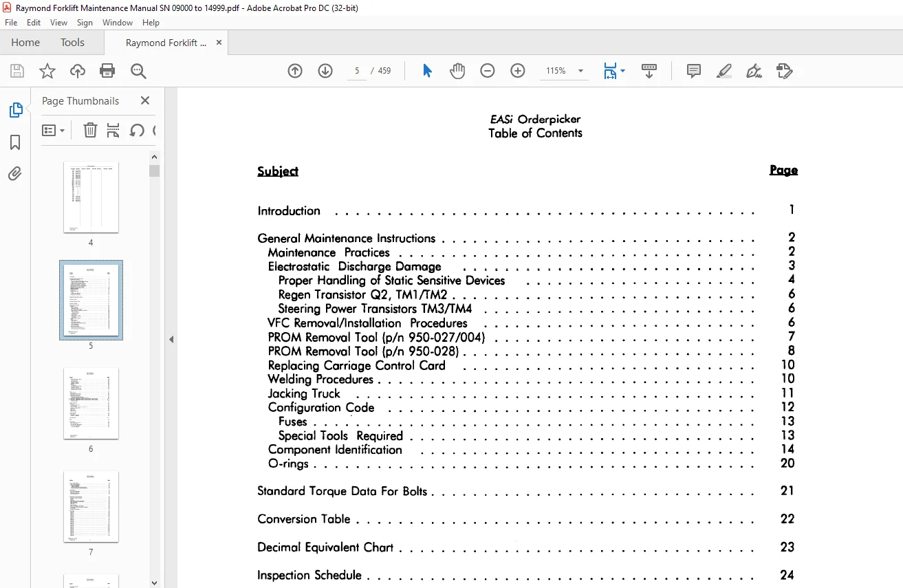
EASi Orderpicker
Table of Contents
Electrostatic Discharge Damage
Proper Handling of Static Sensitive Devices
Regen Transistor Q2, TM1/TM2
Steering Power T ronsistors TM3/TM4
VFC Removal/Installation Procedures
PROM Removal Tool (p/n 950-027/004)
PROM Removal Tool (p/n 950-028)
Replacing Carriage Control Cord
Welding Procedures
Jocking Truck
Configuration Code
Fuses ·
Special Tools Required
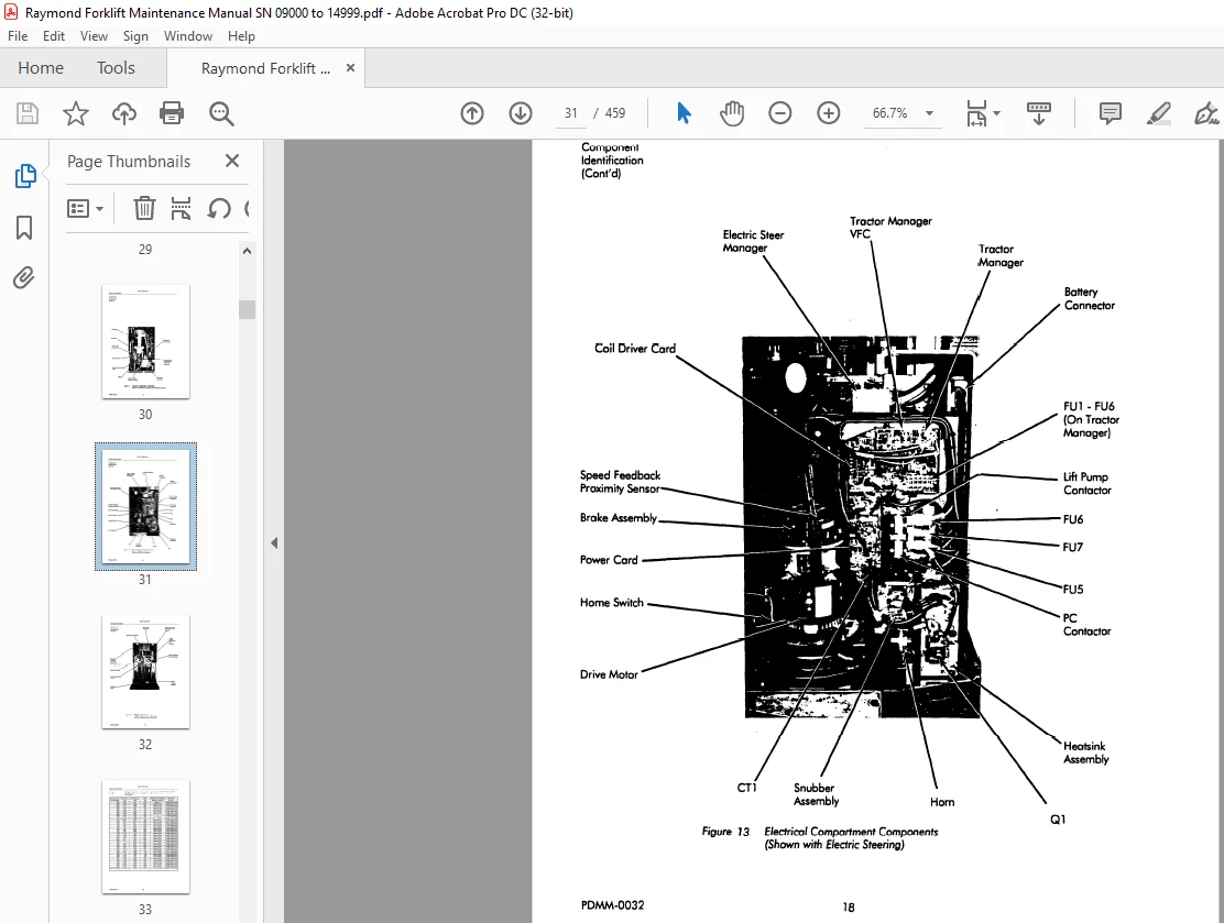
Component Identification
O-rings
Standard Torque Doto For Bolts
Conversion Table
Decimal Equivalent Chart
Inspection Schedule
Scheduled Maintenance
Batteries
Battery Cleaning
Electrolyte Process
Battery Cleaning Procedure
Battery Electrical Leakage To Frame Test
Battery Charging
Charging Process
Hydrometer Use
Voltage Check
Adding Water To Battery
Guidelines
Battery History Record
Motors
Motor Cleaning
Brush Core
Maintenance Schedule
Motor Maintenance Inspection Chart
Brush Replacement
Motor Overheating
Motor Stud T erminols
Motor Test for Open Circuit
Short Circuit Test – Motors
Short Circuit Test
Armature Shorts
Motor Grounds Test
Grounds – General
Hydraulic
Oil Seledion
Changing Reservoir Fluid
Reservoir Fluid Level
Changing Reservoir Filter
Bleeding Hydraulic System
Brake
Brake Control
Deadman Switches 52/523
Brake Deadman Circuit
Periodic Brake Adjustment
Total Gap lnspedion/Adjustment
Brake Rotor Clearance lnspedion/Adjustment
Brake Rotor Replacement (brake p/n 608-008/200 or 608-009 /200)
Brake Rotor Replacement (brake p/n 605-013/200 or 605-014/200)
Deadman Pedal
System Architedure
Overview
Carriage Control Card
Trad or Manager
Advanced intellispeed Manager (Optional)
Operator’s Display (OD)
Power Card
Regen Card
Steer Manager
Communications
BUS+/BUS-
Fundional Operation
Shunt Locations
BSOC
Power Sedion
Drive Transmission Service
Drive Unit Removal
Drive Axle Seal Replacement
Drive Unit Disassembly
Drive Unit Assembly
Manual Cable Steering 66
Manual Coble Steering 66
Manual Cable Steering 67
Theory of Operation 6 7
Manual Steering Wire Rope Adjustment 68
Manual Steering Wire Rope Replacement 69
Power Section 72
Drive Tire Replacement 72
Drive Motor Removal 73
Skid Pad Replacement 7 4
Decal Replacement 75
Performance limiting Messages 78
Initialize To Allow Full Speed 78
Aligning79
Seeking · 79
Cross Upper or lower limit Switch 80
Speed limited Due to Steer Angle 81
lower Side Gate 82
Code lH 82
lower Inhibited 83
Code 1 L Emergency Off Pressed83
Throttle Moved Before Deadman Depressed 84
Lift Inhibited84
Guidance Not learned 85
Fault Codes 86
Code 20 86
Code 21 87
Code 23 88
Code 24 89
Code 25 90
Code 26 91
Code 29 92
Code 2A 93
Code 28 94
Code 2C 95
Code 20 96
Code 2E 97
Code 42 102
Code 43 103
Code 44 104
Code 45 105
Code SO 106
Code 51 108
Code 52 110
Code 53 112
Code 59 114
Code SA 115
Code 58 116
Fault Codes (Cont’d)
Code FG
Code FH
Code FJ
Code GO
Code Gl
Code G2
Code G3
Code G4
Code GS
Code G6
Code GB
Code G9
Code GA
Code Jl
Code J2
Code J4
Modes Of Operation
Audible Alarm Tone Description
Run Mode Tones
Run Mode
Program Mode
Learn Mode
Configure Mode
Maintenance Mode
Password Levels
Password
SuperWrd
Program Tree
Entering Program Mode
To Enter a PASSWORD or SuperWrd
Learn Mode
When to Run Learn
Details Pertaining to Learn
Learn Height/Weight
Learning Wire Frequency
Learning Guide Wire Offsets
Learning Speed Sensor
Learning Steer
Configure Mode
Changing the Access Code
Configure Mode Standard Features
Maintenance Mode
Maintenance Mode – Static
Maintenance Mode – Active
Maintenance Interdependencies
Analog Input Tests
Test A00 – TM + 12 Volt Power Supply
Test A0l – Armature Sense Voltage
Test A02 – Temperature Sensor Voltage
Test A03 – Throttle Pot Voltage
Test A04 – Lift/Lower Pot Voltage
Test A05 – Pressure Sensor Voltage
Test A07 – PC Sense Voltage
Test A08 – Lift Motor Sense Voltage
Test Al0 – Display Ql-C Sense Voltage
Test Al 1 – Display Battery Voltage
Test A 13 – Display The Diagnostic Pendent Voltage
Test Al4 – Display The Field Current Sense Voltage
Test A 15 – Display The Drive Motor Temperature Voltage
Test Al6 – Display The Left Tractor Guidance Coil Voltage
Test A 17 – Display The Right Tractor Guidance Coil Voltage
Test A 18 – Display The Left Load Guidance Coil Voltage
Test A 19 – Right Load Guidance Coil Voltage
Test A20 – T racier Near Wire Coil Voltage
Test A21 – Load Near Wire Coil Voltage
Test A22 – Steer Motor Current
Test A23 – Steer Controller Power Supply Voltage
Test A24 – ESM Battery Sense Voltage
Test A25 – Flow Sensor Temperature Voltage
Test A27 – Maximum Drive Unit Rotation
Test A31 – Average Distance from Wire
Test A32 – Peak Distance from Wire
Test A33 – Average Heading Angle Magnitude
Test A34 – Peak Heading Angle
Test A35 – Average Guide Wire Signal Strength
Test 100 – Lower Mast Reference Switch
Test 101 – Upper Mast Reference Switch
Test 103 – Brake Dead man Switch (S2)
Test 104 – E-Stop Switch
Test 105 – Display Traction Proximity Sensor Value
Test 106 – Display Current Limit Signal
Test 107 – Display Temperature Limit Signal
Test 108 – Rail Guidance Switch
Test 11 0 – Display Flow Sensor Count
Test 111 – Display Auto/Manual Switch
Test 11 3 – Horn Switch
Test 114 – Side Gate Switches
Test 115 – Lift Inhibit Switch
Test 116 – Travel Cutout Switch (S27)
Test 117 – Lift Inhibit Bypass
Test 118 – 60″ Limit Switch (S28)
Test 119 – Channel A, Steer Proximity Sensor
Test 120 – Channel B, Steer Proximity Sensor
Test 121 – Steer Motor Current Limit
Test 122 – Drive Unit Position Encoder Count
Test 123 – Wire Guidance Board Status
Test 124 – Home Position Switch
Test 125 – End-of-Aisle Sensor No2
Test 127 – End-of-Aisle Sensor No1
Test 129 – Traction Speed Feedback Proximity Sensor, Channel A
Test 130 – Traction Speed Feedback Proximity Sensor, Channel B
Test 131 – Carriage Deadman
Test 132 – Brake Deadman Signal From CCC to TM
Test 133 – Display Channel A of Steer Encoder
Test 134 – Display Channel B of Steer Encoder
Test 135 – Lower Inhibit Switch (S25)
Test 136 – 24″/60″ Switch Sense
Test 137 – Upper Reference Switch Sense (Sl0)
Test 138 – Tractor Manager EPO
Test 139 – Spare Tractor Manager Switch (PS15)
Digital Output Tests 269
Test 000 – Toggle the PC Contactor 269
Test 002 – Toggle the P Contactor 271
Test 004 – Reverse Enable Test 273
Test 005 – Forward Enable Test27 4
Test 006 – Toggle Load Hold Solenoid 275
Test 007 – Toggle Horn 277
Test 008 – Brake Release Signal 279
Test 009 – Display Lights 280
Test O 10 – Audible Alarm Test 281
Test O 11 – Chopper Enable Signal 282
Test O 12 – Proportional Solenoid PVvM Ramp 284
Test O 13 – Field PVvM Ramp286
Test O 14 – Armature PVvM Test 288
Test O 15 – Option a I Alarm Test 290
Test O 18 – Regen Enable 291
Traction System 292
Power Transistor Theory 292
Power Transistor Description 293
Hall Effect Switches294
Travel Circuit Components 295
Power Amplifier Components 297
Wiring Conventions297
Traction System Components 298
Tractor Manager298
Power Card•298
Field Transistors (TM 1 & TM2) 298
Power Transistor Control 298
Current Monitoring (CTl) 298
Power Panel Temperature (HT) 298
Signal Verification 299
Power Transistor (Q 1) 299
Regen Transistor (Q2) 299
Snubber Capacitor (Cl) 299
Snubber Capacitor (C2) 299
Recirculating Rectifier (REC 1) 299
Regen Braking Rectifier (REC2) 299
Snubber Rectifier (REC3) 299
Snubber Rectifier (REC4) 299
Snubber Resistor (R2) 299
Snubber Resistor (R3) 299
Operation of the Travel System 300
Connecting Battery 300
Turning Key Switch (Sl) ON 302
Startup Sequence 305
SelfT est Checks 306
Closing Deadman Switch (52 and 523) 309
Moving Directional/Speed Control 311
Contactor Coils 314
Closed Loop Speed Control 315
I Revised 11/01/94
PDMM-0032 viii
EASi Orderpicker
Table of Contents
Subject
Torque On Demand
Thermal Cut-Back
Elevated Height Limits
Current Limiting
Proportional Plugging
Regenerative Braking
Drive
Regenerative Braking Operation
Power Transistor (Q 1) Test
Regen Transistor (Q2) Test
TM1/rM2 Test
TM3/rM4 Test
Testing Other Electrical Components
RECl and REC4 Test
R2 or R3 Test
Testing Capacitors (Cl & C2)
Power Panel Service Information
Lift/Lower System
System Overview
Unique System Features
Introduction
Single Speed Lift/Lower
Single Speed Lift/Lower Theory
Lift
Lower
Emergency Lower
Variable Lift/Lower
Variable Lift
Variable Lower•
Variable Lift/Lower Functional Block Diagram
Variable Lift/Lower Emergency Lowering
Fork Hong-up Protection
T we-Stage Lift Cylinder Removal
2-Stage Lift Cylinder Service
Cleaning
2-Stoge Lift Cylinder Reassembly
Center Lift Cylinder Removal (3-Stage)
Center Lift Cylinder Service (3-Stage)
Cleaning Components • •
Center Lift Cylinder (3-Stage) Reassembly
High Pressure Relief Valve Adjustment
Lift/Lower Manifold Service
Bleeding Side Lift Cylinders
Bleeding Center Cylinder
Lift/Lower Return Spring Replacement
VR2 Replacement
Lift/Lower Hydraulic Troubleshooting ••
Suggested Procedures – Hydraulic Troubleshooting For Lift/Lower
Pump Problems
Hydraulic Problems
Options
EASi Orderpicker
Table of Contents
Subjed
intellispeed™
Hydraulic Flow Sensor
Non-Condudive Hoses
Flow Sensor Module (FSM)
intellispeed Theory
Height Sensing
intellispeed Hydraulic Flow Sensor
Hydraulic Flow Sensor Pickup Test
Hydraulic Flow Sensor Servicing
Hydraulic Flow Sensor Removal
Flow Sensor Disassembly
2-Stage Elevating System Service Notes
3-Stage Elevating System Service Notes
Line Driver Adjustment Procedure
Options
Auto Steer Centering
End-of-aisle Control
Aisle Entry
Aisle Exit
Sensor Adjustment
End-of-Aisle Configurations
End-of-Aisle Magnet Installation Information
Troubleshooting
Wiring – General
Shorts To Frame
Voltage To Frame
Troubleshooting intellidrive
Learn Mode and Troubleshooting
Board and Component Swapping Precautions
Likelihood of Component Failure
Handling Printed Circuit Cards
SMARTi™ System Problems
Appendix
Schematic, Hydraulic
Schematic, Electrical (Sheet 1 of 3)
With Carriage Control Card p/n 154-012-377 Rev D or Lower
Schematic, Electrical (Sheet 2 of 3)
With Carriage Control Card p/n 154-012-377 Rev D or Lower
Schematic, Eledrical (Sheet 3 of 3)
With Carriage Control Card p/n 154-012-377 Rev Dor Lower
Schematic, Eledrical (Sheet 1 of 3)
With Carriage Control Card p/n 154-012-377 Rev E or Higher
Schematic, Eledrical (Sheet 2 of 3)
With Carriage Control Card p/n 154-012-377 Rev E or Higher
Schematic, Electrical (Sheet 3 of 3)
With Carriage Control Card p/n 154-012-377 Rev E or Higher
Need help? Contact: [email protected]
IMAGES PREVIEW OF THE MANUAL:
PLEASE NOTE:
- This is the SAME manual used by the dealers to troubleshoot any faults in your vehicle. This can be yours in 2 minutes after the payment is made.
- Contact us at [email protected] should you have any queries before your purchase or that you need any other service / repair / parts operators manual.
S.V