Raymond Forklift MODEL537 TRACTOR & MAST PARTS CATALOG MANUAL – PDF DOWNLOAD
$25.95
Raymond Forklift 537 TRACTOR & MAST PARTS CATALOG MANUAL – PDF DOWNLOAD
Description
Raymond Forklift MODEL537 TRACTOR & MAST PARTS CATALOG MANUAL – PDF DOWNLOAD
FILE DETAILS:
Raymond Forklift MODEL537 TRACTOR & MAST PARTS CATALOG MANUAL – PDF DOWNLOAD
Language : English
Pages :196
Downloadable : Yes
File Type : PDF
Size: 15.1 MB
DESCRIPTION:
Raymond Forklift MODEL537 TRACTOR & MAST PARTS CATALOG MANUAL – PDF DOWNLOAD
Introduction to Your Parts Catalog
Introduction
The Raymond Corporation manufactures a variety of lift trucks in both standard and customized configurations. The Parts Catalog is organized into major divisions which cover all areas of the truck.
These may include:
•Power Unit (if applicable) • Hydraulic (if applicable)
• Brake and Steering • Elevating/ Attachments
• Drive Unit • Contactors
• Electrical • Special Options (if applicable)
Using the Catalog
The catalog contains three elements necessary for effective use, which are:
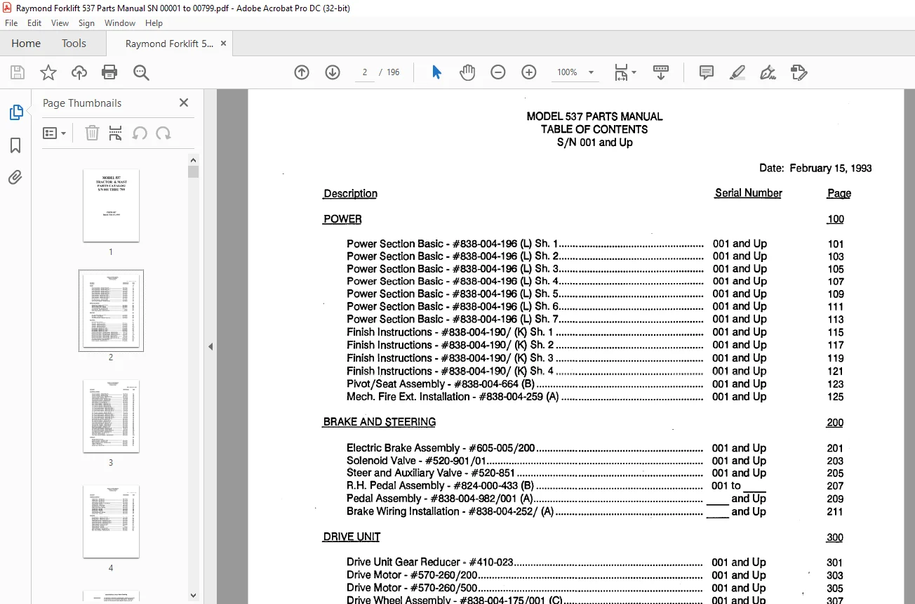
TABLE OF CONTENTS:
Raymond Forklift MODEL537 TRACTOR & MAST PARTS CATALOG MANUAL – PDF DOWNLOAD
Description
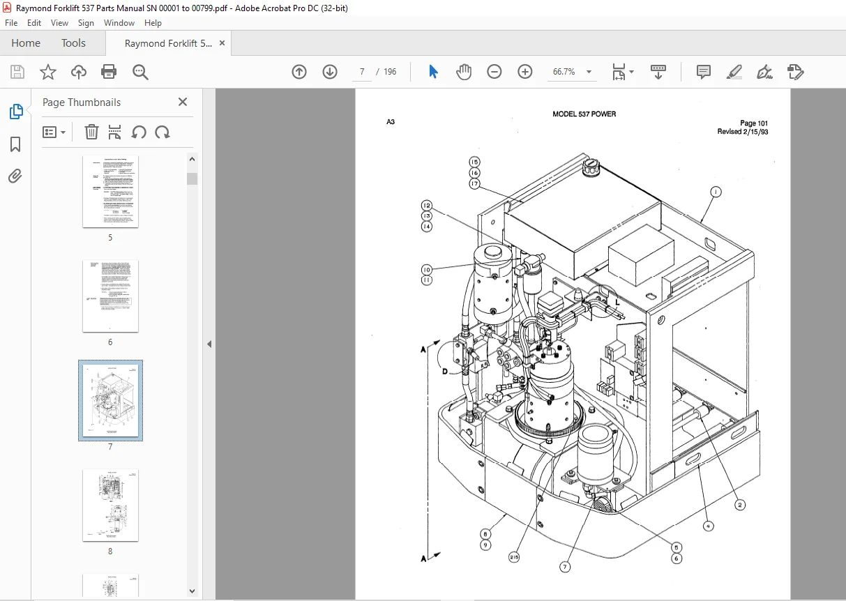
POWER
Power Section Basic – #838-004-196 (L) Sh 1 001 and Up
Power Section Basic – #838-004-196 (L) Sh 2 001 and Up
Power Section Basic – #838-004-196 (L) Sh 3 001 and Up
Power Section Basic – #838-004-196 (L) Sh 4 001 and Up
Power Section Basic – #838-004-196 (L) Sh 5 001 and Up
Power Section Basic – #838-004-196 (L) Sh 6 001 and Up
Power Section Basic – #838-004-196 (L) Sh 7 001 and Up
Finish Instructions – #838-004-190/ (K) Sh 1 001 and Up
Finish Instructions- #838-004-190/ (K) Sh 2 001 and Up
Finish Instructions – #838-004-190/ (K) Sh 3 001 and Up
Finish Instructions – #838-004-190/ (K) Sh 4 001 and Up
Pivot/Seat Assembly – #838-004-664 (8) 001 and Up
Mech Fire Ext Installation – #838-004-259 (A) 001 and Up
BRAKE AND STEERING
Electric Brake Assembly- #605-005/200 001 and Up
Solenoid Valve – #520-901 /01 001 and Up
Steer and Auxiliary Valve – #520-851 ; 001 and Up
R H Pedal Assembly – #824-000-433 (B) 001 to
Pedal Assembly – #838-004-982/001 (A) and Up
Brake Wiring Installation – #838-004-252/ (A) ‘ = and Up
DRIVE UNIT
Drive Unit Gear Reducer – #410-023 001 and Up
Drive Motor – #570-260/200 001 and Up
Drive Motor – #570-260/500 001 and Up
Drive Wheel Assembly- #838-004-175/001 (C) 001 and Up
ELECTRICAL
Standard Electrical Symbols
Schematic – #838-004-435 (K) Sh 1
Schematic – #838-004-435 (K) Sh 2 ;
Schematic – #838-004-435 (K) Sh 3
Schematic – #838-004-435 (K) Sh 4
Final Assembly – #838-004-191 / (L) Sh 1
Final Assembly- #838-004-191/ (L) Sh 2
Final Assembly- #838-004-191/ (L) Sh 3
Final Assembly- #838-004-191 / (L) Sh 4
Electrical Control System – (Carriage Manager) – #838-004-598 (A)
Electrical Control System – (Carriage Manager) – #838-004-878 (A)
Electrical Control System – (Carriage Manager) – #838-004-973/001 (C)
Electrical Control System – (Vehicle Manager) – #838-004-599 (A) :
Electrical Control System – (Vehicle Manager) – #838-004-871 (A)
Electrical Control System – (Vehicle Manager) – #838-004-971 /001 (D)
Card Cage Housing Assembly – #838-004-637 / (D)
Encoder Shaft Assembly – #838-004-647 (E)
Detector Assembly- #828-003-420/ (E)
Firmware Installation – #838-004-883/ (8)
Contactor Assembly – #838-004-793 (B)
Contactor Assembly – #838-004-876 (B3)
Transducer Module Assembly – #828-003-614/ (C)
Resistor Assembly – #838-004-198 (C) ;
Traverse Resistor Assembly – #838-004-549 (B)
Traverse Resistor Assembly – #838-007-049 (B)
Rotate Resistor Assembly – #838-004-550 (C)
Switch Assembly – #114-006-580/ (E) :
Mech Handles Installation – #838-004-607 / (A)
Mech Handles Installation – #838-004-607 / (B)
LH Control Arm Assembly – #838-004-708/ (E)
LH Control Arm Assembly – #838-004-789/ (AS)
L H Control Handle Assembly – #838-004-650 / (B) Sh 1
L H Control Handle Assembly – #838-004-650/ (B) Sh 2
L H Control Handle Assembly – #838-004-652/ (D1) Sh 1
L H Control Handle Assembly – #838-004-652/ (D1) Sh 2
R H Control Arm Assembly – #838-004-709/ (81)
R H Control Arm Assembly – #838-004-790/ (A3)
R H Control Handle Assembly – #838-004-651 / (B) Sh 1
R H Control Handle Assembly – #838-004-651/ (B) Sh 2
R H Control Handle Assembly – #838-004-653/ (D1) Sh 1
R H Control Handle Assembly – #838-004-653/ (D1) Sh 2
Warning Light Elec Installation – #838-004-636/ (C)
Warning Light Assembly – #114-007-671 / (A)
Elec Lights, Fan Installation – #838-004-623/ (E)
Cover and Fan Assembly – #838-004-710/ (D)
Cover and Bin Light Assembly – #838-004-711 / (C)
Travel Light Elec Installation – #838-004-633/ (8)
Gate Switch Elec Installation – #838-004-634 (A)
Wire Guidance Installation – #838-004-217 / (E)
Sensor Frame Assembly – #170-002-191 / (L)
Flow Sensor Module Assembly – #838-004-413 (8)
Flow Sensor Module Assembly – #838-004-880 (A)
Flow Sensor Module Assembly – #838-004-972/002 (C)
Lift Limit Electrical Installation – #838-004-858/ (C)
Heater Plate Assembly – #114-006-704/ (D)
Can Fuse Kit – #838-004-993 (8)
Power Option Electrical Installation – #838-004-969 (B)
Standard Hydraulic Symbols
Hydraulic Schematic – #838-004-134 (B) 001 and Up
Reservoir Assembly – #838-004-201 (C) 001 and Up
Platform Manifold Assembly – #838-004-402 (E) 001 and Up
Lift Pump – #500-420/ 001 and Up
Lift Motor – #570-261 /200 001 and Up
Auxiliary Pump – #500-417 /201 001 and Up
Auxiliary Motor – #570-222/100
Auxiliary Motor- #570-222/150
Auxiliary Motor – #570-222/200
Auxiliary Motor – #570-222/400
Tach Generator Assembly – #114-007-697 (A)
Hydraulic Motor- #550-017
Hydraulic Motor – #838-004-922/
Reach/Rotate Valve – #520-853
Auxiliary Control Valve – #520-852
Solenoid Valve – #520-908
Solenoid Valve – #520-909
Hydraulic Motor – #550-019
Pump and Relief Valve – #520-849 • ,
Lift Select Valve – #520-850
Elevating Section – #838-004-197 / (K) Sh 1 001 and Up
Elevating Section – #838-004-197 / (K) Sh 2 001 and Up
Elevating Section – #838-004-197 / (K) Sh 3 001 and Up
Auxiliary Mast Assembly – #838-004-520/ (K) Sh 1 001 and Up
Auxiliary Mast Assembly- #838-004-520/ (K) Sh 2 001 and Up
Auxiliary Mast Assembly – #838-004-520/ (K) Sh 3 001 and Up
Cylinder Assembly- #154-012-251/ (D2) 001 and Up
Cylinder Assembly – #154-012-207 / (D) 001 and Up
Cylinder Assembly – #540-060/ 001 to
Cylinder Assembly – #540-063/ and Up
Cylinder Assembly- #154-012-249/ (B4) 001 and Up
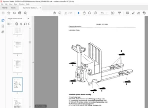
Mech Fork Installation – #838-004-194/ (C1) 001 and Up
Mech Tether Installation – #838-004-635/ (A) 001 and Up
IMAGES PREVIEW OF THE MANUAL:
Customer Support: [email protected]
https://vimeo.com/836419155?share=copy
PLEASE NOTE:
- This is the same manual used by the dealers to diagnose and troubleshoot your vehicle
- You will be directed to the download page as soon as the purchase is completed. The whole payment and downloading process will take anywhere between 2-5 minutes
- Need any other service / repair / parts manual, please feel free to contact [email protected] . We still have 50,000 manuals unlisted
s.m