Raymond Forklift RAS2025 Adjustable Baseleg Walkie Straddle Maintenance Manual RAS-06-02001 & Up – PDF DOWNLOAD
$26.95
Raymond Forklift RAS2025 Adjustable Baseleg Walkie Straddle Maintenance Manual RAS-06-02001 & Up – PDF DOWNLOAD
Description
Raymond Forklift RAS2025 Adjustable Baseleg Walkie Straddle Maintenance Manual RAS-06-02001 & Up – PDF DOWNLOAD
FILE DETAILS:
Raymond Forklift RAS2025 Adjustable Baseleg Walkie Straddle Maintenance Manual RAS-06-02001 & Up – PDF DOWNLOAD
Language : English
Pages :251
Downloadable : Yes
File Type : PDF
Size:8.27 MB
DESCRIPTION:
Raymond Forklift RAS2025 Adjustable Baseleg Walkie Straddle Maintenance Manual RAS-06-02001 & Up – PDF DOWNLOAD
User Manual Design
This manual is designed to give personnel, with an expected level of expertise, the technical information necessary to maintain, troubleshoot, and repair a Raymond product. The two-line running page header at the top of each page contains the name of the manual, the title of the current section, and the topic of the current page.
This manual includes the following sections:
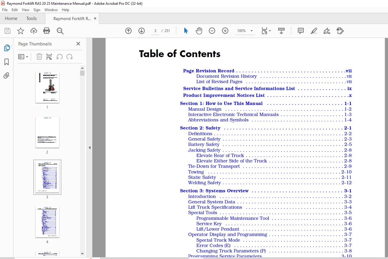
TABLE OF CONTENTS:
Raymond Forklift RAS2025 Adjustable Baseleg Walkie Straddle Maintenance Manual RAS-06-02001 & Up – PDF DOWNLOAD
Page Revision Record vii
Document Revision History vii
List of Revised Pages vii
Service Bulletins and Service Informations List ix
Product Improvement Notices List x
Section 1: How to Use This Manual 1-1
Manual Design 1-2
Interactive Electronic Technical Manuals 1-3
Abbreviations and Symbols 1-4
Section 2: Safety 2-1
Definitions 2-2
General Safety 2-3
Battery Safety 2-5
Jacking Safety 2-8
Elevate Rear of Truck 2-8
Elevate Either Side of the Truck 2-8
Tie-Down for Transport 2-9
Towing 2-10
Static Safety 2-11
Welding Safety 2-12
Section 3: Systems Overview 3-1
Introduction 3-2
General System Data 3-3
Lift Truck Specifications 3-4
Special Tools 3-5
Programmable Maintenance Tool 3-6
Service Key 3-6
Lift/Lower Pendant 3-6
Operator Display and Programming 3-7
Special Truck Mode 3-7
Error Codes (E) 3-7
Changing Truck Parameters (P) 3-8
Programming Service Parameters 3-10
Service Parameter Display (Keypad Only) 3-10
Setting Individual PIN-Key Codes (Keypad Only) 3-11
Display Part Numbers (Pn) 3-14
Service Input/Output Display 3-15
Digital Inputs/Outputs from Traction Power Amplifier 3-16
Modes of Operation 3-18
Programmable Maintenance Tool (PMT) 3-18
Diagnostic Mode 3-18
Accessing Diagnostic Mode 3-18
Clear 3-19
Real Time Monitor Mode 3-19
Traction Power Amplifier System Mode 3-19
Table of Contents Adjustable Baseleg Walkie Straddle Maintenance Manual
ii Publication: 1055925, Revised: 31 Jul 2014
TruckCom 3-20
Layout 3-21
Disconnect Function 3-23
Downloading Program Function 3-24
Parameters Function 3-26
Diagnostics Function 3-28
Other Menu Functions 3-31
FlashWare 3-32
Overview 3-32
Requirements 3-32
Installing FlashWare on PC 3-32
Connecting PC to Truck 3-32
Starting FlashWare 3-33
Section 4: Scheduled Maintenance 4-1
Scheduled Maintenance Guidelines 4-2
Initial 90 Day/250 Deadman Hour (HD) Maintenance 4-3
Every 180 Days or 500 Deadman Hours (HD) 4-4
Every 360 Days or 2000 Deadman Hours (HD) 4-6
Lubrication Points 4-7
Contactor Tip Inspection 4-8
Chain Maintenance 4-9
Fork Inspection 4-10
Section 5: Troubleshooting 5-1
How to Use This Section 5-2
Electrical Troubleshooting Guidelines 5-3
General 5-3
Shorts to Frame 5-3
DC Electric Motor 5-6
DC Motor Types 5-6
Inspection 5-6
Service 5-6
Open Circuit Motor Test 5-8
Grounded Motor Test 5-9
Short-Circuited Armature 5-9
Short-Circuited Winding 5-9
Hydraulic Troubleshooting Guidelines 5-10
Symptom Tables: Travel System (Forward/Reverse) 5-11
Symptom Tables: Wiring System 5-15
Symptom Tables: Electrical Problems 5-16
Section 6: Messages and Codes 6-1
List of Messages and Codes 6-2
Traction Power Amplifier Flash Codes 6-3
Caution and Error Codes 6-5
Messages and Caution Codes 6-6
Code ‘TEST’ 6-6
Code ‘SLO’ 6-6
Code C14 6-6
Code C19 6-7
Code C20 6-7
Code C21 6-7
Code C28 6-8
Adjustable Baseleg Walkie Straddle Maintenance Manual Table of Contents
Publication: 1055925, Revised: 31 Jul 2014 iii
Code C29 6-8
Code C41 6-9
Code C42 6-9
Code C43 6-10
Code C44 6-10
Code C46 6-11
Code C77 6-12
Code C78 6-12
Code C96 6-12
Code C98 6-13
Error Codes 6-14
Code E101 6-14
Code E104 6-14
Code E106 6-15
Code E110 6-15
Code E112 6-16
Code E114 6-16
Code E115 6-17
Code E118 6-18
Code E140 6-18
Code E141 6-18
Code E142 6-19
Code E150 6-19
Code E151 6-20
Code E157 6-20
Code E159 6-21
Code E160 6-21
Code E161 6-22
Code E200 6-22
Code E201 6-23
Code E202 6-23
Code E214 6-24
Section 7: Component Procedures 7-1
List of Component Procedures 7-2
Component Locator Photos 7-5
Covers and Finish 7-6
Removal 7-6
Steering and Controls 7-7
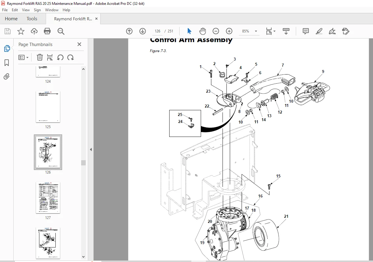
Control Arm Assembly 7-8
Control Arm Removal 7-9
Control Head Assembly 7-10
Control Head Removal 7-11
Control Head Installation 7-12
Drive and Brake 7-13
Drive Unit 7-14
Removal 7-14
Disassembly 7-16
Assembly 7-16
Installation 7-17
Drive Housing Lubrication 7-17
Table of Contents Adjustable Baseleg Walkie Straddle Maintenance Manual
iv Publication: 1055925, Revised: 31 Jul 2014
Drive Wheel 7-18
Removal 7-18
Tire Pressing Procedure 7-19
Installation 7-20
Electromagnetic Brake 7-21
Brake Disc Location 7-21
Airgap Adjustment 7-21
Friction Disc Replacement 7-21
Mechanically Releasing the Brake 7-22
Drive Motor 7-23
Component Parts 7-23
Brush Inspection and Replacement 7-24
Motor Disassembly 7-26
Installation 7-26
Electrical Components 7-29
Battery 7-30
Inspection and Care 7-30
Removal 7-34
Installation 7-34
Battery Connector 7-35
Contactors 7-37
Fuses 7-38
Fuse Test/Inspection 7-38
Horn 7-39
Removal 7-39
Installation 7-39
Master Control Relay 7-40
Inspection/Test 7-40
Traction Power Amplifier 7-41
Basics of Circuit Operation 7-41
Motor Circuit 7-42
Control Circuit 7-42
Cleaning the Traction Power Amplifier 7-43
Traction Power Amplifier Removal 7-43
Traction Power Amplifier Installation 7-43
Power Cables 7-44
Power Cable Repair 7-44
Switches 7-46
Main ON/OFF Switch 7-47
Arm Angle Switches 7-47
Key Switch (Optional) 7-51
Wiring Harness 7-52
Wiring Harness Terminology 7-52
Wiring Harness Inspection 7-52
Wiring Harness Repair 7-52
Wiring Harness Soldering Procedures 7-53
Hydraulic Components 7-55
Hydraulic System 7-56
Hydraulic Diagram and Components 7-56
Main Components 7-56
Adjustable Baseleg Walkie Straddle Maintenance Manual Table of Contents
Publication: 1055925, Revised: 31 Jul 2014 v
Lift Cylinder 7-60
Removal 7-60
Disassembly/Assembly 7-60
Installation 7-61
Reservoir 7-62
Removal 7-62
Inspection 7-62
Installation 7-62
Filter Screen 7-63
Removal 7-63
Inspection 7-63
Installation 7-63
Mast, Chain, Hose, Cable 7-65
Main Mast 7-66
Guidance Damper 7-66
Adjusting Mast Guides/Dampers 7-67
Carriage Removal and Mast Disassembly 7-68
Outrigger Assembly 7-70
General 7-70
Maintenance 7-71
Support Arm Width Adjustment 7-71
Load Wheels 7-73
Lift Chain 7-75
Lift Chain Adjustment 7-75
Options 7-77
Cold Storage Conditioning 7-78
Section 8: Theory of Operation 8-1
Definitions 8-2
Acceleration 8-2
Arm Angle Switches 8-2
Click-to-Creep 8-2
Continuity 8-2
Controller Area Network (CAN) 8-2
Creep Speed 8-2
Current Limiting 8-3
Deceleration 8-3
Emergency Reverse 8-3
Fault Codes 8-3
Open Circuit 8-3
Overvoltage Cutoff 8-3
PIN-Key Code 8-3
Pulse Width Modulation 8-3
Regenerative Braking 8-3
Short-Circuit or Short 8-3
Speed Limiting 8-4
Thermal Cutback (Traction Power Amplifier) 8-4
Tractor 8-4
Truck Off Delay (Keypad only) 8-4
Undervoltage Cutoff 8-4
Vehicle Manager 8-4
Table of Contents Adjustable Baseleg Walkie Straddle Maintenance Manual
vi Publication: 1055925, Revised: 31 Jul 2014
Direction/Speed Control 8-5
Control Arm Positioning 8-5
Travel Request, Forks Trailing 8-5
Travel Request, Forks-First 8-5
Emergency Reverse 8-6
Truck Starting 8-6
Lift/Lower System 8-7
Lift 8-7
Lower 8-7
Traction System 8-8
Vehicle Manager 8-8
Traction Power Amplifier 8-8
Section A: Appendix A-1
Lubrication Equivalency Chart A-2
Thread Adhesives, Sealants, and Lubricants A-3
Component Specific Service/Torque Chart A-4
Torque Chart – Standard (Ferrous) A-5
Torque Chart – Standard (Brass) A-6
Torque Chart – Metric (Ferrous) A-7
Torque Chart – Metric (Brass) A-8
Torque Chart – Thread-Forming Screws A-8
Torque Chart – Hydraulic Fittings A-9
Torque Chart – Straight Thread Face Seal O-Rings A-10
Decimal Equivalent Chart A-11
Standard/Metric Conversions A-13
Section I: Index I-1
IMAGES PREVIEW OF THE MANUAL:
Questions? Email us: [email protected]
https://vimeo.com/837104652?share=copy
PLEASE NOTE:
- This is the SAME exact manual used by your dealers to fix your vehicle.
- The same can be yours in the next 2-3 mins as you will be directed to the download page immediately after paying for the manual.
- Any queries / doubts regarding your purchase, please feel free to contact [email protected]
S.M